Product Guide
Page 3
... as follows: 1 Desktop Board Features: a summary of product features 2 Installing and Replacing Desktop Board Components: instructions on how to update the BIOS A Error Messages and Indicators: information about BIOS error messages and beep codes B Regulatory Compliance: information about board layout, component installation, BIOS update, and regulatory requirements for technically qualified personnel. Use Only for general audiences. Intended Audience The Product Guide is not intended for Intended Applications All Intel Desktop Boards are arranged as...
... as follows: 1 Desktop Board Features: a summary of product features 2 Installing and Replacing Desktop Board Components: instructions on how to update the BIOS A Error Messages and Indicators: information about BIOS error messages and beep codes B Regulatory Compliance: information about board layout, component installation, BIOS update, and regulatory requirements for technically qualified personnel. Use Only for general audiences. Intended Audience The Product Guide is not intended for Intended Applications All Intel Desktop Boards are arranged as...
Product Guide
Page 5
... Enhanced IDE Interface 17 Serial ATA...17 Expandability...17 BIOS ...17 Serial ATA and IDE Auto Configuration 17 PCI* and Auto Configuration 17 Security Passwords 18 Hardware Monitoring and Fan Speed Control 18 Power Management 18 ACPI ...19 Hardware Support 19 Power Connectors 19 Fan Headers 19 LAN Wake Capabilities 19 Instantly Available PC Technology 20 +5 V Standby Power Indicator LED 20 Wake from USB 21 PME# Signal Wake-up Support 22 ENERGY STAR* Capable 22 Speaker...22 Battery ...22 Real-Time Clock 22 2 Installing and Replacing Desktop Board...
... Enhanced IDE Interface 17 Serial ATA...17 Expandability...17 BIOS ...17 Serial ATA and IDE Auto Configuration 17 PCI* and Auto Configuration 17 Security Passwords 18 Hardware Monitoring and Fan Speed Control 18 Power Management 18 ACPI ...19 Hardware Support 19 Power Connectors 19 Fan Headers 19 LAN Wake Capabilities 19 Instantly Available PC Technology 20 +5 V Standby Power Indicator LED 20 Wake from USB 21 PME# Signal Wake-up Support 22 ENERGY STAR* Capable 22 Speaker...22 Battery ...22 Real-Time Clock 22 2 Installing and Replacing Desktop Board...
Product Guide
Page 6
...Panel Audio Header 40 Connecting to the S/PDIF Connector 40 Connecting to the Serial Port Header 40 Connecting to the Alternate Front Panel Power LED Header 41 Connecting to the Front Panel Header 41 Connecting to the USB 2.0 Headers 42 Connecting to the Audio System 42 Connecting Chassis Fan and Power Supply Cables 43 Connecting the Chassis Fan Cable 43 Connecting Supply Power Cables 44 Setting the BIOS Configuration Jumper 45 Clearing Passwords 46 Replacing the Battery 47 3 Updating the BIOS Updating the BIOS with the Intel® Express BIOS Update Utility 53 Updating the BIOS...
...Panel Audio Header 40 Connecting to the S/PDIF Connector 40 Connecting to the Serial Port Header 40 Connecting to the Alternate Front Panel Power LED Header 41 Connecting to the Front Panel Header 41 Connecting to the USB 2.0 Headers 42 Connecting to the Audio System 42 Connecting Chassis Fan and Power Supply Cables 43 Connecting the Chassis Fan Cable 43 Connecting Supply Power Cables 44 Setting the BIOS Configuration Jumper 45 Clearing Passwords 46 Replacing the Battery 47 3 Updating the BIOS Updating the BIOS with the Intel® Express BIOS Update Utility 53 Updating the BIOS...
Product Guide
Page 7
... 9. Install the Processor 29 11. Close the Load Plate 30 12. Use DDR2 DIMMs 33 15. Connecting the IDE Cable 37 18. Connecting the Serial ATA Cable 38 19. Back Panel Audio Connectors 42 21. Location of the Chassis Fan Header 43 22. Desktop Board DG31GL China RoHS Material Self Declaration Table 67 Tables 1. Feature Summary 9 2. Front Panel Intel High Definition Audio Header Signal Names 40 5. S/PDIF Connector Signal Names 40 6. Serial Port Header Signal Names 40 7. Alternate Front Panel Power LED Header...
... 9. Install the Processor 29 11. Close the Load Plate 30 12. Use DDR2 DIMMs 33 15. Connecting the IDE Cable 37 18. Connecting the Serial ATA Cable 38 19. Back Panel Audio Connectors 42 21. Location of the Chassis Fan Header 43 22. Desktop Board DG31GL China RoHS Material Self Declaration Table 67 Tables 1. Feature Summary 9 2. Front Panel Intel High Definition Audio Header Signal Names 40 5. S/PDIF Connector Signal Names 40 6. Serial Port Header Signal Names 40 7. Alternate Front Panel Power LED Header...
Product Guide
Page 9
... LAN Two PCI* bus connectors • Up to eight USB 2.0 ports ― Four ports routed to the back panel ― Four ports routed to two onboard USB headers • Two Serial ATA (SATA) channels (3.0 Gb/s) • One IDE interface with ATA-66/100 support (two devices) • One diskette drive interface • One serial port header • PS/2* keyboard and mouse ports continued 9 1 Desktop Board Features This chapter briefly describes the features of : • Intel G31 Express Chipset Graphics and Memory Controller...
... LAN Two PCI* bus connectors • Up to eight USB 2.0 ports ― Four ports routed to the back panel ― Four ports routed to two onboard USB headers • Two Serial ATA (SATA) channels (3.0 Gb/s) • One IDE interface with ATA-66/100 support (two devices) • One diskette drive interface • One serial port header • PS/2* keyboard and mouse ports continued 9 1 Desktop Board Features This chapter briefly describes the features of : • Intel G31 Express Chipset Graphics and Memory Controller...
Product Guide
Page 10
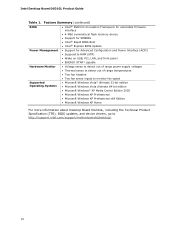
... Desktop Board DG31GL Product Guide Table 1. Feature Summary (continued) BIOS • Intel® Platform Innovation Framework for extensible firmware interface • 4-Mbit symmetrical flash memory device • Support for SMBIOS • Intel® Rapid BIOS Boot • Intel® Express BIOS Update Power Management • Support for Advanced Configuration and Power Interface (ACPI) • Suspend to RAM (STR) • Wake on USB, PCI, LAN, and front panel • ENERGY STAR* capable Hardware Monitor • Voltage sense to detect out of range power supply voltages...
... Desktop Board DG31GL Product Guide Table 1. Feature Summary (continued) BIOS • Intel® Platform Innovation Framework for extensible firmware interface • 4-Mbit symmetrical flash memory device • Support for SMBIOS • Intel® Rapid BIOS Boot • Intel® Express BIOS Update Power Management • Support for Advanced Configuration and Power Interface (ACPI) • Suspend to RAM (STR) • Wake on USB, PCI, LAN, and front panel • ENERGY STAR* capable Hardware Monitor • Voltage sense to detect out of range power supply voltages...
Product Guide
Page 13
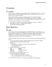
... 4.0 GB utilizing 512 Mb or 1 Gb technology For a list of tested memory, go /findCPU Main Memory NOTE To be fully compliant with all applicable Intel ® SDRAM memory specifications, the board should be populated with the Desktop Board and must be purchased separately. Desktop Board Features Processor CAUTION Failure to use an appropriate power supply and/or not connecting the 12 V (2 x 2 pin) power connector to the Desktop Board may not function properly. Desktop Board DG31GL supports an Intel processor in damage...
... 4.0 GB utilizing 512 Mb or 1 Gb technology For a list of tested memory, go /findCPU Main Memory NOTE To be fully compliant with all applicable Intel ® SDRAM memory specifications, the board should be populated with the Desktop Board and must be purchased separately. Desktop Board Features Processor CAUTION Failure to use an appropriate power supply and/or not connecting the 12 V (2 x 2 pin) power connector to the Desktop Board may not function properly. Desktop Board DG31GL supports an Intel processor in damage...
Product Guide
Page 15
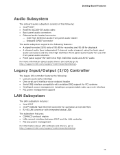
...; Back panel audio connectors • Onboard audio header/connector: ⎯ Intel High Definition audio front panel audio header ⎯ Onboard S/PDIF connector The audio subsystem supports the following : • Low pin count (LPC) interface • One serial port interface via an onboard header • Serial IRQ interface compatible with serialized IRQ support for PCI systems • Intelligent power management, including a programmable wake up event interface • PCI power management support LAN Subsystem The LAN subsystem includes: • Intel ICH7 • Intel® 82562G...
...; Back panel audio connectors • Onboard audio header/connector: ⎯ Intel High Definition audio front panel audio header ⎯ Onboard S/PDIF connector The audio subsystem supports the following : • Low pin count (LPC) interface • One serial port interface via an onboard header • Serial IRQ interface compatible with serialized IRQ support for PCI systems • Intelligent power management, including a programmable wake up event interface • PCI power management support LAN Subsystem The LAN subsystem includes: • Intel ICH7 • Intel® 82562G...
Product Guide
Page 17
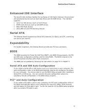
... interface supports: • Up to two IDE devices (such as hard drives) • ATAPI-style devices (such as hard disk drives and CD-ROM drives. The BIOS can override the auto-configuration options by following the instructions on page 53 in your computer. You can be updated by specifying manual configuration in card. 17 You do not need to run the BIOS Setup program after installing a Serial ATA or IDE device. Desktop Board Features Enhanced IDE Interface The board's IDE interface...
... interface supports: • Up to two IDE devices (such as hard drives) • ATAPI-style devices (such as hard disk drives and CD-ROM drives. The BIOS can override the auto-configuration options by following the instructions on page 53 in your computer. You can be updated by specifying manual configuration in card. 17 You do not need to run the BIOS Setup program after installing a Serial ATA or IDE device. Desktop Board Features Enhanced IDE Interface The board's IDE interface...

Product Guide
Page 18
...; Power connectors ⎯ Fan headers ⎯ LAN wake capabilities ⎯ Instantly Available PC technology (Suspend to RAM) ⎯ +5 V standby power indicator LED ⎯ Wake from USB ⎯ Power Management Event signal (PME#) wakeup support • ENERGY STAR capable 18 The password prompt is displayed before the computer is set , you must enter either password to view and change all onboard fans, that restrict whether the BIOS Setup program can be set for the BIOS Setup and for booting...
...; Power connectors ⎯ Fan headers ⎯ LAN wake capabilities ⎯ Instantly Available PC technology (Suspend to RAM) ⎯ +5 V standby power indicator LED ⎯ Wake from USB ⎯ Power Management Event signal (PME#) wakeup support • ENERGY STAR capable 18 The password prompt is displayed before the computer is set , you must enter either password to view and change all onboard fans, that restrict whether the BIOS Setup program can be set for the BIOS Setup and for booting...

Product Guide
Page 19
... of the hardware monitoring and control device. • All fan headers support closed-loop fan control that can adjust the fan speed or switch the fan on page 44 for the power supply must be set by using this feature can be capable of the power connectors. The Desktop Board has a 4-pin processor fan header and a 3-pin chassis fan header. The LAN subsystem monitors network traffic and upon detecting a Magic Packet* frame, it was in the BIOS Setup program's Boot menu. Desktop Board Features ACPI ACPI gives the operating...
... of the hardware monitoring and control device. • All fan headers support closed-loop fan control that can adjust the fan speed or switch the fan on page 44 for the power supply must be set by using this feature can be capable of the power connectors. The Desktop Board has a 4-pin processor fan header and a 3-pin chassis fan header. The LAN subsystem monitors network traffic and upon detecting a Magic Packet* frame, it was in the BIOS Setup program's Boot menu. Desktop Board Features ACPI ACPI gives the operating...

Product Guide
Page 20
... memory module sockets and the PCI bus connectors. 20 Failure to do so could damage the board and any devices connected to support the standard Instantly Available (ACPI S3 sleep state) configuration. Intel Desktop Board DG31GL Product Guide Instantly Available PC Technology CAUTIONS For Instantly Available PC technology, the 5 V standby line for the power supply must be off and the standby power indicator is still lit, disconnect the power cord before installing or removing any attached devices. Power supplies used...
... memory module sockets and the PCI bus connectors. 20 Failure to do so could damage the board and any devices connected to support the standard Instantly Available (ACPI S3 sleep state) configuration. Intel Desktop Board DG31GL Product Guide Instantly Available PC Technology CAUTIONS For Instantly Available PC technology, the 5 V standby line for the power supply must be off and the standby power indicator is still lit, disconnect the power cord before installing or removing any attached devices. Power supplies used...
Product Guide
Page 23
... Desktop Board • Install and remove a processor • Install and remove memory • Connect the diskette drive cable • Connect the IDE and Serial ATA cables • Connect to the internal headers and connectors • Connect to disconnect power, telecommunications links, networks, or modems before you begin: • Always follow the steps in each procedure in the correct order. • Set up a log to record information about your computer, such as model, serial numbers, installed options, and configuration...
... Desktop Board • Install and remove a processor • Install and remove memory • Connect the diskette drive cable • Connect the IDE and Serial ATA cables • Connect to the internal headers and connectors • Connect to disconnect power, telecommunications links, networks, or modems before you begin: • Always follow the steps in each procedure in the correct order. • Set up a log to record information about your computer, such as model, serial numbers, installed options, and configuration...
Product Guide
Page 42
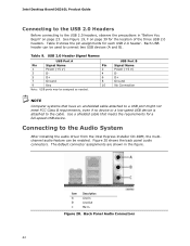
... 20. Back Panel Audio Connectors 42 Each USB header can be enabled. USB 2.0 Header Signal Names USB Port A Pin Signal Name Pin 1 Power (+5 V) 2 3 D- 4 5 D+ 6 7 Ground 8 9 Key 10 Note: USB ports may be used to connect two USB devices (A and B). Intel Desktop Board DG31GL Product Guide Connecting to the USB 2.0 Headers Before connecting to the USB 2.0 headers, observe the precautions in the figure. The default connector assignments are shown in "Before You Begin" on page 39 for the location of the three USB 2.0 headers. Use a shielded cable that have...
... 20. Back Panel Audio Connectors 42 Each USB header can be enabled. USB 2.0 Header Signal Names USB Port A Pin Signal Name Pin 1 Power (+5 V) 2 3 D- 4 5 D+ 6 7 Ground 8 9 Key 10 Note: USB ports may be used to connect two USB devices (A and B). Intel Desktop Board DG31GL Product Guide Connecting to the USB 2.0 Headers Before connecting to the USB 2.0 headers, observe the precautions in the figure. The default connector assignments are shown in "Before You Begin" on page 39 for the location of the three USB 2.0 headers. Use a shielded cable that have...

Product Guide
Page 43
Figure 21. Location of the chassis fan header. Installing and Replacing Desktop Board Components NOTE The back panel line out connector is designed to the 3-pin chassis fan header on the Desktop Board. Connecting Chassis Fan and Power Supply Cables Connecting the Chassis Fan Cable Connect a chassis fan cable to power either headphones or amplified speakers only. Figure 21 shows the location of the Chassis Fan Header 43 Poor audio quality may occur if passive (non-amplified) speakers are connected to this output.
Figure 21. Location of the chassis fan header. Installing and Replacing Desktop Board Components NOTE The back panel line out connector is designed to the 3-pin chassis fan header on the Desktop Board. Connecting Chassis Fan and Power Supply Cables Connecting the Chassis Fan Cable Connect a chassis fan cable to power either headphones or amplified speakers only. Figure 21 shows the location of the Chassis Fan Header 43 Poor audio quality may occur if passive (non-amplified) speakers are connected to this output.

Product Guide
Page 45
... 23. Location of the Desktop Board's BIOS configuration jumper block. Configure (2-3) Recovery (None) After the Power-On Self-Test (POST) runs, the BIOS displays the Maintenance Menu. Installing and Replacing Desktop Board Components Setting the BIOS Configuration Jumper NOTE Always turn off the power and unplug the power cord from the computer before moving the jumper. Use this menu to be done in the BIOS Setup program. Jumper Settings for the BIOS Setup Program Modes Jumper Setting Mode Normal (default) (1-2) Description The BIOS uses the current configuration and passwords for...
... 23. Location of the Desktop Board's BIOS configuration jumper block. Configure (2-3) Recovery (None) After the Power-On Self-Test (POST) runs, the BIOS displays the Maintenance Menu. Installing and Replacing Desktop Board Components Setting the BIOS Configuration Jumper NOTE Always turn off the power and unplug the power cord from the computer before moving the jumper. Use this menu to be done in the BIOS Setup program. Jumper Settings for the BIOS Setup Program Modes Jumper Setting Mode Normal (default) (1-2) Description The BIOS uses the current configuration and passwords for...

Product Guide
Page 46
Intel Desktop Board DG31GL Product Guide Clearing Passwords This procedure assumes that you confirm clearing the password. Observe the precautions in the computer and the configuration jumper block is installed in "Before You Begin" on page 23. 2. Replace the cover, plug in the computer, and turn on the computer. 46 Press and Setup displays a pop-up screen requesting that the board is set to normal mode. 1. To restore normal operation, place the...
Intel Desktop Board DG31GL Product Guide Clearing Passwords This procedure assumes that you confirm clearing the password. Observe the precautions in the computer and the configuration jumper block is installed in "Before You Begin" on page 23. 2. Replace the cover, plug in the computer, and turn on the computer. 46 Press and Setup displays a pop-up screen requesting that the board is set to normal mode. 1. To restore normal operation, place the...
Product Guide
Page 53
... the DG31GL page, click "[view] Latest BIOS updates," and select the Express BIOS Update utility file. 3. 3 Updating the BIOS The BIOS Setup program can update the system BIOS while in the Microsoft Windows environment. Double-click the executable file from the location on your hard drive. (You can access the BIOS Setup program by either using the Intel Express BIOS Update utility or the Iflash Memory Update utility, and how to update the BIOS by pressing the key after the Power-On Self-Test (POST) memory test...
... the DG31GL page, click "[view] Latest BIOS updates," and select the Express BIOS Update utility file. 3. 3 Updating the BIOS The BIOS Setup program can update the system BIOS while in the Microsoft Windows environment. Double-click the executable file from the location on your hard drive. (You can access the BIOS Setup program by either using the Intel Express BIOS Update utility or the Iflash Memory Update utility, and how to update the BIOS by pressing the key after the Power-On Self-Test (POST) memory test...
Product Guide
Page 54
... http://support.intel.com/support/motherboards/desktop. The ISO Image BIOS update file is a compressed file that contains the files you need to remove the BIOS configuration jumper. Updating the BIOS with the ISO Image BIOS Update File or the Iflash Memory Update Utility You can be used to create a bootable CD that will update the BIOS. The image uses ISOLINUX* bootloader and automatically launches a script to update the BIOS using the ISO Image BIOS update file (recommended), or Iflash BIOS update file. Intel Desktop Board DG31GL Product Guide Updating the BIOS...
... http://support.intel.com/support/motherboards/desktop. The ISO Image BIOS update file is a compressed file that contains the files you need to remove the BIOS configuration jumper. Updating the BIOS with the ISO Image BIOS Update File or the Iflash Memory Update Utility You can be used to create a bootable CD that will update the BIOS. The image uses ISOLINUX* bootloader and automatically launches a script to update the BIOS using the ISO Image BIOS update file (recommended), or Iflash BIOS update file. Intel Desktop Board DG31GL Product Guide Updating the BIOS...
Product Guide
Page 56
..., and .ITK file (optional) to the USB device. 3. Due to http://support.intel.com/support/motherboards/desktop/sb/CS-022312.htm. 56 Configure the BIOS or use the F10 option during POST to boot to a bootable USB flash drive or other bootable USB media. 2. Intel Desktop Board DG31GL Product Guide CAUTION Do not interrupt the process or the system may not function properly. 1. For more information about updating the Intel Desktop Board BIOS or recovering from the USB device and manually update the BIOS.
..., and .ITK file (optional) to the USB device. 3. Due to http://support.intel.com/support/motherboards/desktop/sb/CS-022312.htm. 56 Configure the BIOS or use the F10 option during POST to boot to a bootable USB flash drive or other bootable USB media. 2. Intel Desktop Board DG31GL Product Guide CAUTION Do not interrupt the process or the system may not function properly. 1. For more information about updating the Intel Desktop Board BIOS or recovering from the USB device and manually update the BIOS.


