Product Guide
Page 5
Contents 1 Desktop Board Features Desktop Board Components 12 Processor ...14 System Memory 14 Mobile Intel® 945GSE Express Chipset 14 Intel 945GSE Graphics Subsystem 15 Operating System Support 16 Onboard Audio Subsystem 16 Legacy Input/Output (I/O) Controller 17 Network Bootloader ...the PCI Express Full-Mini Card Slot 34 Installing an Intel® Z-U130 USB Solid-State Drive (or Compatible Device 35 Connecting to the Internal Headers and Connectors 36 Internal Connectors and Headers 37 Connecting a Chassis Fan 46 Setting the BIOS Configuration Jumper 47 Clearing Passwords ...
Contents 1 Desktop Board Features Desktop Board Components 12 Processor ...14 System Memory 14 Mobile Intel® 945GSE Express Chipset 14 Intel 945GSE Graphics Subsystem 15 Operating System Support 16 Onboard Audio Subsystem 16 Legacy Input/Output (I/O) Controller 17 Network Bootloader ...the PCI Express Full-Mini Card Slot 34 Installing an Intel® Z-U130 USB Solid-State Drive (or Compatible Device 35 Connecting to the Internal Headers and Connectors 36 Internal Connectors and Headers 37 Connecting a Chassis Fan 46 Setting the BIOS Configuration Jumper 47 Clearing Passwords ...
Product Guide
Page 7
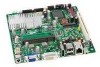
...Device) Support 45 15. Front Panel Header 43 22. Front-panel Power LED Blink and Internal Speaker Beep Codes 59 26. Intel Desktop Board D945GSEJT Components 12 2. LAN Status LEDs 18 3. Removing System Memory 32 8. ENERGY STAR Requirements 25 5. PS/2 Keyboard Port Header 38...Messages 60 27. LAN Status LEDs 18 4. Location of the Chassis Fan Header 46 16. Internal Headers and Connectors 36 12. Intel Desktop Board D945GSEJT Mounting Screw Holes 30 6. Connection Diagram for Intel HD Audio 40 17. BIOS Configuration Jumper Block 47 17. Connection Diagram...
...Device) Support 45 15. Front Panel Header 43 22. Front-panel Power LED Blink and Internal Speaker Beep Codes 59 26. Intel Desktop Board D945GSEJT Components 12 2. LAN Status LEDs 18 3. Removing System Memory 32 8. ENERGY STAR Requirements 25 5. PS/2 Keyboard Port Header 38...Messages 60 27. LAN Status LEDs 18 4. Location of the Chassis Fan Header 46 16. Internal Headers and Connectors 36 12. Intel Desktop Board D945GSEJT Mounting Screw Holes 30 6. Connection Diagram for Intel HD Audio 40 17. BIOS Configuration Jumper Block 47 17. Connection Diagram...
Product Guide
Page 9
...; Atom™ processor N270 • One 200-pin Double Data Rate 2 (DDR2) Small Outline Dual Inline Memory Module (SO-DIMM) socket with gold-plated contacts • Support for DDR2 533 MHz SO-DIMMs (DDR2 800 MHz and DDR2 667 MHz validated to monitor fan activity • Fan speed control 9 one header supports an Intel® Z-U130... Card slot • Seven USB 2.0 ports: ― Three back panel ports ― Four front panel ports (via two internal headers; Table 1 summarizes the features of Intel® Desktop Board D945GSEJT.
...; Atom™ processor N270 • One 200-pin Double Data Rate 2 (DDR2) Small Outline Dual Inline Memory Module (SO-DIMM) socket with gold-plated contacts • Support for DDR2 533 MHz SO-DIMMs (DDR2 800 MHz and DDR2 667 MHz validated to monitor fan activity • Fan speed control 9 one header supports an Intel® Z-U130... Card slot • Seven USB 2.0 ports: ― Three back panel ports ― Four front panel ports (via two internal headers; Table 1 summarizes the features of Intel® Desktop Board D945GSEJT.
Product Guide
Page 22
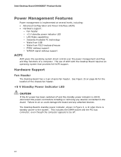
... DIMM socket and the PCI bus connector, even though the computer appears to do so could damage the board and any devices connected to the system. Hardware Support Fan Header The Desktop Board has a 3-pin chassis fan header. Intel Desktop Board D945GSEJT Product Guide Power Management Features Power management is implemented at several levels, including: • Advanced Configuration and...
... DIMM socket and the PCI bus connector, even though the computer appears to do so could damage the board and any devices connected to the system. Hardware Support Fan Header The Desktop Board has a 3-pin chassis fan header. Intel Desktop Board D945GSEJT Product Guide Power Management Features Power management is implemented at several levels, including: • Advanced Configuration and...
Product Guide
Page 24
...a wakeup signal that supports wake from an ACPI S1, S3, S4, or S5 state. 24 Intel Desktop Board D945GSEJT Product Guide Instantly Available PC Technology Instantly Available PC technology enables the board to be used to its last known state. The LAN subsystem network adapter monitors network traffic at the... Media Independent Interface. The board supports LAN wake capabilities with ACPI in power management and can be off (the hard drive(s) and fan will power off, the front panel power LED will appear to enter the ACPI...
...a wakeup signal that supports wake from an ACPI S1, S3, S4, or S5 state. 24 Intel Desktop Board D945GSEJT Product Guide Instantly Available PC Technology Instantly Available PC technology enables the board to be used to its last known state. The LAN subsystem network adapter monitors network traffic at the... Media Independent Interface. The board supports LAN wake capabilities with ACPI in power management and can be off (the hard drive(s) and fan will power off, the front panel power LED will appear to enter the ACPI...
Product Guide
Page 27
...8226; Install and remove the Desktop Board • Install and remove system memory • Connect SATA drives • Install a Wireless LAN card • Install an Intel Z-U130 USB Solid-State Drive (or compatible device) • Connect to internal headers • Connect a chassis fan cable • Set the ... (ESD) can result in personal injury or equipment damage. Some circuitry on the board can continue to operate even though the front panel power button is not available, you begin installing the Desktop Board: • Always follow the steps in each procedure in the correct order. ...
...8226; Install and remove the Desktop Board • Install and remove system memory • Connect SATA drives • Install a Wireless LAN card • Install an Intel Z-U130 USB Solid-State Drive (or compatible device) • Connect to internal headers • Connect a chassis fan cable • Set the ... (ESD) can result in personal injury or equipment damage. Some circuitry on the board can continue to operate even though the front panel power button is not available, you begin installing the Desktop Board: • Always follow the steps in each procedure in the correct order. ...
Product Guide
Page 37
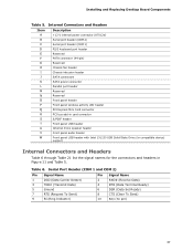
... power connector (ATX12V) Serial port header (COM 2) Serial port header (COM 1) PS/2 keyboard port header Reserved PATA connector (44-pin) Reserved Chassis fan header Chassis intrusion header SATA connectors SATA power connector Parallel port header Reserved Reserved Front panel header Front panel wireless activity LED header PCI Express...Internal mono speaker header Front panel audio header Front panel USB header with Intel Z-U130 USB Solid-State Drive (or compatible device) support Internal Connectors and...10 Key (no pin) 37 Installing and Replacing Desktop Board Components Table 5.
... power connector (ATX12V) Serial port header (COM 2) Serial port header (COM 1) PS/2 keyboard port header Reserved PATA connector (44-pin) Reserved Chassis fan header Chassis intrusion header SATA connectors SATA power connector Parallel port header Reserved Reserved Front panel header Front panel wireless activity LED header PCI Express...Internal mono speaker header Front panel audio header Front panel USB header with Intel Z-U130 USB Solid-State Drive (or compatible device) support Internal Connectors and...10 Key (no pin) 37 Installing and Replacing Desktop Board Components Table 5.
Product Guide
Page 46
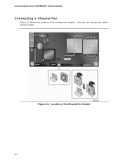
Location of the chassis fan header. Figure 15. Connect the chassis fan cable to this header. Intel Desktop Board D945GSEJT Product Guide Connecting a Chassis Fan Figure 15 shows the location of the Chassis Fan Header 46
Location of the chassis fan header. Figure 15. Connect the chassis fan cable to this header. Intel Desktop Board D945GSEJT Product Guide Connecting a Chassis Fan Figure 15 shows the location of the Chassis Fan Header 46


