Product Guide
Page 5
Contents 1 Desktop Board Features Desktop Board Components 11 Processor ...13 Main Memory ...14 Intel® 845GV Chipset ...15 Audio Subsystem ...15 LAN Subsystem (Optional 16 LAN Subsystem Software 16 RJ-45 LAN Connector LEDs 16 Hi-Speed USB ... and Removing Memory 28 Installing DIMMs ...28 Removing DIMMs ...29 Connecting the IDE Cable 30 Connecting Internal Headers 31 Connecting the Front Panel Header 32 Installing a Front Panel Audio Solution 32 Installing a USB 2.0 Solution 33 Connecting Hardware Control and Power Cables 34 Connecting Hardware Control Cables 35 Connecting Power ...
Contents 1 Desktop Board Features Desktop Board Components 11 Processor ...13 Main Memory ...14 Intel® 845GV Chipset ...15 Audio Subsystem ...15 LAN Subsystem (Optional 16 LAN Subsystem Software 16 RJ-45 LAN Connector LEDs 16 Hi-Speed USB ... and Removing Memory 28 Installing DIMMs ...28 Removing DIMMs ...29 Connecting the IDE Cable 30 Connecting Internal Headers 31 Connecting the Front Panel Header 32 Installing a Front Panel Audio Solution 32 Installing a USB 2.0 Solution 33 Connecting Hardware Control and Power Cables 34 Connecting Hardware Control Cables 35 Connecting Power ...
Product Guide
Page 6
Intel Desktop Board D845GVSR Product Guide Connecting Add-In Card and Peripheral Interface Connectors 36 Setting the BIOS Configuration Jumper Block 37 Clearing Passwords ...38 Back Panel Connectors ...39 Replacing the Battery ...40 3 Updating the BIOS Updating the BIOS with the Intel® Express BIOS Update Utility 45 Updating the BIOS with the Intel...Hard Disk Drives Submenu 71 Removable Devices Submenu 72 ATAPI CD-ROM Drives 73 Exit Menu ...74 5 Desktop Board Resources Memory Map ...75 DMA Channels ...75 Interrupts ...76 A Error Messages and Indicators BIOS Beep Codes ...77 BIOS ...
Intel Desktop Board D845GVSR Product Guide Connecting Add-In Card and Peripheral Interface Connectors 36 Setting the BIOS Configuration Jumper Block 37 Clearing Passwords ...38 Back Panel Connectors ...39 Replacing the Battery ...40 3 Updating the BIOS Updating the BIOS with the Intel® Express BIOS Update Utility 45 Updating the BIOS with the Intel...Hard Disk Drives Submenu 71 Removable Devices Submenu 72 ATAPI CD-ROM Drives 73 Exit Menu ...74 5 Desktop Board Resources Memory Map ...75 DMA Channels ...75 Interrupts ...76 A Error Messages and Indicators BIOS Beep Codes ...77 BIOS ...
Product Guide
Page 7
...of Conformity Statement 81 Product Ecology Statements 82 EMC Regulations ...83 Product Certification Markings (Board Level 84 Figures 1. Removing the Battery from the Desktop Board 43 vii Contents B Regulatory Compliance Safety Regulations ...81 European Union Declaration of Hardware ...Power Connectors 34 11. Desktop Board Mounting Screw Holes 25 5. Installing the I/O Shield 24 4. Installing Memory...28 8. Add-in Card and Peripheral Interface Connectors 36 12. Back Panel Connectors 39 14. Connecting the IDE Cable 30 9. Desktop Board Components 11 2. Internal ...
...of Conformity Statement 81 Product Ecology Statements 82 EMC Regulations ...83 Product Certification Markings (Board Level 84 Figures 1. Removing the Battery from the Desktop Board 43 vii Contents B Regulatory Compliance Safety Regulations ...81 European Union Declaration of Hardware ...Power Connectors 34 11. Desktop Board Mounting Screw Holes 25 5. Installing the I/O Shield 24 4. Installing Memory...28 8. Add-in Card and Peripheral Interface Connectors 36 12. Back Panel Connectors 39 14. Connecting the IDE Cable 30 9. Desktop Board Components 11 2. Internal ...
Product Guide
Page 8
... Submenu 70 30. Beep Codes ...77 38. BIOS Setup Program Menu Bar 49 11. System Memory Map...75 35. Desktop Board Components 12 3. PCI Configuration Submenu 53 16. Boot Configuration Submenu 54 17. Chipset Configuration Submenu 64 25. Removable Devices Submenu... 37. EMC Regulations ...83 41. Feature Summary ...9 2. Hard Disk Drives Submenu 71 31. Video Configuration Submenu 62 23. Front Panel Header (J9G1 32 7. Intel Desktop Board D845GVSR Product Guide Tables 1. ACPI Submenu ...68 28. USB 2.0 Header (J9F2 33 9. Jumper Settings for the BIOS Setup Program Modes...
... Submenu 70 30. Beep Codes ...77 38. BIOS Setup Program Menu Bar 49 11. System Memory Map...75 35. Desktop Board Components 12 3. PCI Configuration Submenu 53 16. Boot Configuration Submenu 54 17. Chipset Configuration Submenu 64 25. Removable Devices Submenu... 37. EMC Regulations ...83 41. Feature Summary ...9 2. Hard Disk Drives Submenu 71 31. Video Configuration Submenu 62 23. Front Panel Header (J9G1 32 7. Intel Desktop Board D845GVSR Product Guide Tables 1. ACPI Submenu ...68 28. USB 2.0 Header (J9F2 33 9. Jumper Settings for the BIOS Setup Program Modes...
Product Guide
Page 9
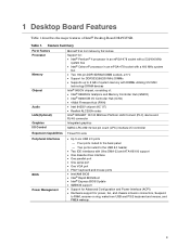
...Expansion Capabilities Three PCI slots Peripheral Interfaces BIOS Power Management • Up to six USB 2.0 ports - 1 Desktop Board Features Table 1 describes the major features of system memory with Ultra DMA-33 and ATA-66/100 support &#...Intel/AMI BIOS • Intel® Rapid BIOS Boot • Intel® Express BIOS Update • SMBIOS support • Support for Advanced Configuration and Power Interface (ACPI) • Hardware support for DDR333/266/200 MHz DIMMs • Supports up to 2 GB of Intel® Desktop Board D845GVSR. Table 1. Four ports routed to the back panel...
...Expansion Capabilities Three PCI slots Peripheral Interfaces BIOS Power Management • Up to six USB 2.0 ports - 1 Desktop Board Features Table 1 describes the major features of system memory with Ultra DMA-33 and ATA-66/100 support &#...Intel/AMI BIOS • Intel® Rapid BIOS Boot • Intel® Express BIOS Update • SMBIOS support • Support for Advanced Configuration and Power Interface (ACPI) • Hardware support for DDR333/266/200 MHz DIMMs • Supports up to 2 GB of Intel® Desktop Board D845GVSR. Table 1. Four ports routed to the back panel...

Product Guide
Page 12
... IDE connector M Speaker N Battery O Auxiliary front panel power LED connector P Front chassis fan header Q Chassis intrusion header R BIOS S Front panel header T Front panel USB header U PCI connectors Related Links: Go to the following links for more information about Intel Desktop Board D845GVSR: • http://www.intel.com/design/motherbd • http://support.intel.com/support/motherboards/desktop 12 Intel Desktop Board D845GVSR Product Guide Table 2.
... IDE connector M Speaker N Battery O Auxiliary front panel power LED connector P Front chassis fan header Q Chassis intrusion header R BIOS S Front panel header T Front panel USB header U PCI connectors Related Links: Go to the following links for more information about Intel Desktop Board D845GVSR: • http://www.intel.com/design/motherbd • http://support.intel.com/support/motherboards/desktop 12 Intel Desktop Board D845GVSR Product Guide Table 2.

Product Guide
Page 15
...-ROM • Front panel audio connector • Back panel connectors: - Poor audio quality may occur if passive (non-amplified) speakers are connected to power either headphones or amplified speakers only. Line out - Related Links: Go to the following audio interfaces: • ATAPI-style connectors: - Desktop Board Features Intel® 845GV Chipset The Intel 845GV chipset consists...
...-ROM • Front panel audio connector • Back panel connectors: - Poor audio quality may occur if passive (non-amplified) speakers are connected to power either headphones or amplified speakers only. Line out - Related Links: Go to the following audio interfaces: • ATAPI-style connectors: - Desktop Board Features Intel® 845GV Chipset The Intel 845GV chipset consists...
Product Guide
Page 16
... established. On (brighter and pulsing) The computer is operating. USB 1.1 devices will function normally at : http://support.intel.com/support/motherboards/desktop/ RJ-45 LAN Connector LEDs Two LEDs are backward compatible with status indicator LEDs • Programmable transit threshold •...that do not support USB 2.0. 16 four ports routed to the back panel and two routed to the cable. Intel Desktop Board D845GVSR Product Guide LAN Subsystem (Optional) The optional Intel 82562ET (with another computer on Intel's World Wide Web site at USB 1.1 speeds. Table 5. On (...
... established. On (brighter and pulsing) The computer is operating. USB 1.1 devices will function normally at : http://support.intel.com/support/motherboards/desktop/ RJ-45 LAN Connector LEDs Two LEDs are backward compatible with status indicator LEDs • Programmable transit threshold •...that do not support USB 2.0. 16 four ports routed to the back panel and two routed to the cable. Intel Desktop Board D845GVSR Product Guide LAN Subsystem (Optional) The optional Intel 82562ET (with another computer on Intel's World Wide Web site at USB 1.1 speeds. Table 5. On (...

Product Guide
Page 19
... multiple wake events from the following link: http://support.intel.com/support/motherboards/desktop/ 19 When signaled by first selecting the desktop board from the PCI and/or USB buses exceeds power supply capacity, the desktop board may lose register settings stored in memory. Figure 2. Suspend... Links: For more information on the front panel, the sleep state is standby power to support the standard Instantly Available (ACPI S3 sleep state) configuration. Failure to provide adequate standby current when using this desktop board must be connected to the chassis intrusion header...
... multiple wake events from the following link: http://support.intel.com/support/motherboards/desktop/ 19 When signaled by first selecting the desktop board from the PCI and/or USB buses exceeds power supply capacity, the desktop board may lose register settings stored in memory. Figure 2. Suspend... Links: For more information on the front panel, the sleep state is standby power to support the standard Instantly Available (ACPI S3 sleep state) configuration. Failure to provide adequate standby current when using this desktop board must be connected to the chassis intrusion header...
Product Guide
Page 21
... you open the computer or perform any of the midboard and front panel connectors provide operating voltage (+5 V dc and +12 V dc, for powering devices external to devices inside the computer chassis, such as fans and internal peripherals. 2 Installing and Replacing Desktop Board Components This chapter tells you how to disconnect power, telecommunications links...
... you open the computer or perform any of the midboard and front panel connectors provide operating voltage (+5 V dc and +12 V dc, for powering devices external to devices inside the computer chassis, such as fans and internal peripherals. 2 Installing and Replacing Desktop Board Components This chapter tells you how to disconnect power, telecommunications links...
Product Guide
Page 31
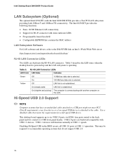
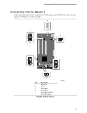
A F 1 2 3 4 5 6 7 9 10 J8A1 J7A1 B J6B1 E 1 2 3 4 5 6 7 8 10 J9F2 C 1 2 3 4 5 6 7 8 9 J9G1 13 J8H3 D Item A B C D E F Description Auxiliary-in CD-in Front panel Power LED Front panel USB 2.0 Front panel audio Figure 9. Internal Headers OM16279 31 Installing and Replacing Desktop Board Components Connecting Internal Headers Follow the instructions below to connect the USB 2.0 solution, power LED, front panel, and audio solution. See Figure 9 for pin assignments.
A F 1 2 3 4 5 6 7 9 10 J8A1 J7A1 B J6B1 E 1 2 3 4 5 6 7 8 10 J9F2 C 1 2 3 4 5 6 7 8 9 J9G1 13 J8H3 D Item A B C D E F Description Auxiliary-in CD-in Front panel Power LED Front panel USB 2.0 Front panel audio Figure 9. Internal Headers OM16279 31 Installing and Replacing Desktop Board Components Connecting Internal Headers Follow the instructions below to connect the USB 2.0 solution, power LED, front panel, and audio solution. See Figure 9 for pin assignments.

Product Guide
Page 32
... the computer and disconnect the AC power cord. 3. Remove the three jumpers from the header (this disables the back panel audio connectors). 5. Intel Desktop Board D845GVSR Product Guide Connecting the Front Panel Header Before connecting the front panel header, observe the precautions in "Before You Begin" on page 21. Observe the precautions in "Before You Begin" on...
... the computer and disconnect the AC power cord. 3. Remove the three jumpers from the header (this disables the back panel audio connectors). 5. Intel Desktop Board D845GVSR Product Guide Connecting the Front Panel Header Before connecting the front panel header, observe the precautions in "Before You Begin" on page 21. Observe the precautions in "Before You Begin" on...
Product Guide
Page 33
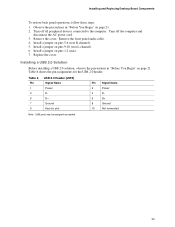
Install a jumper on pins 5-6 (rear R channel). 5. Installing and Replacing Desktop Board Components To restore back panel operations, follow these steps: 1. Installing a USB 2.0 Solution Before installing a USB 2.0 solution, observe the precautions in "Before You Begin" on page 21. 2. Table 8. Observe the precautions ... 4 D- 6 D+ 8 Ground 10 Not connected Note: USB ports may be assigned as needed. 33 Table 8 shows the pin assignments for the USB 2.0 header. Remove the front panel audio cable. 4.
Install a jumper on pins 5-6 (rear R channel). 5. Installing and Replacing Desktop Board Components To restore back panel operations, follow these steps: 1. Installing a USB 2.0 Solution Before installing a USB 2.0 solution, observe the precautions in "Before You Begin" on page 21. 2. Table 8. Observe the precautions ... 4 D- 6 D+ 8 Ground 10 Not connected Note: USB ports may be assigned as needed. 33 Table 8 shows the pin assignments for the USB 2.0 header. Remove the front panel audio cable. 4.

Product Guide
Page 39
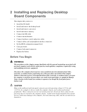
... in Audio line out Audio line in Figure 13. Installing and Replacing Desktop Board Components Back Panel Connectors ✏ NOTE The line out connector, located on the back panel, is designed to this output. Back Panel Connectors OM16283 39 Figure 13 shows the back panel connectors. Poor audio quality may occur if passive (non-amplified) speakers...
... in Audio line out Audio line in Figure 13. Installing and Replacing Desktop Board Components Back Panel Connectors ✏ NOTE The line out connector, located on the back panel, is designed to this output. Back Panel Connectors OM16283 39 Figure 13 shows the back panel connectors. Poor audio quality may occur if passive (non-amplified) speakers...
User Guide
Page 5
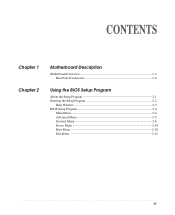
CONTENTS Chapter 1 Chapter 2 Motherboard Description Motherboard Overview 1-3 Rear Panel Connectors 1-4 Using the BIOS Setup Program About the Setup Program 2-1 Entering the Setup Program 2-2 Help Window 2-3 BIOS Setup Program 2-4 Main Menu ...2-4 Advanced Menu 2-5 Security Menu 2-8 Power Menu ...2-10 Boot Menu ...2-10 Exit Menu ...2-12 iii
CONTENTS Chapter 1 Chapter 2 Motherboard Description Motherboard Overview 1-3 Rear Panel Connectors 1-4 Using the BIOS Setup Program About the Setup Program 2-1 Entering the Setup Program 2-2 Help Window 2-3 BIOS Setup Program 2-4 Main Menu ...2-4 Advanced Menu 2-5 Security Menu 2-8 Power Menu ...2-10 Boot Menu ...2-10 Exit Menu ...2-12 iii
User Guide
Page 9
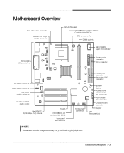
... Power supply connector FDD connector CD audio connector Video audio connector Front panel audio connector Realtek ALC202A audio codec Intel 82562ET 10/100 Mbps (PLC) device PCI slots Intel 82801DB I/O controller Hub (ICH4) Front panel USB connector Front panel connector NOTE The motherboard's components may vary and look slightly different. Primary EIDE connector Secondary EIDE connector...
... Power supply connector FDD connector CD audio connector Video audio connector Front panel audio connector Realtek ALC202A audio codec Intel 82562ET 10/100 Mbps (PLC) device PCI slots Intel 82801DB I/O controller Hub (ICH4) Front panel USB connector Front panel connector NOTE The motherboard's components may vary and look slightly different. Primary EIDE connector Secondary EIDE connector...
User Guide
Page 10
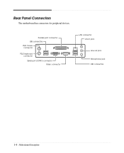
Rear Panel Connectors The motherboard has connectors for peripheral devices. Parallel port connector USB connectors PS/2 mouse connector PS/2 keyboard connector Serial port (COM1) connector Video connector LAN connector Line-in jack Line-out jack Microphone jack USB connectors 1-4 Motherboard Description
Rear Panel Connectors The motherboard has connectors for peripheral devices. Parallel port connector USB connectors PS/2 mouse connector PS/2 keyboard connector Serial port (COM1) connector Video connector LAN connector Line-in jack Line-out jack Microphone jack USB connectors 1-4 Motherboard Description
User Guide
Page 23
...motherboard can continue to install board options in your board options may look a bit different from any telecommunications links, networks, or modems before you open the computer or perform any of devices and board options. Installing Board Options This chapter describes how to operate even though the front panel...the computer chassis. Failure to install a variety of the procedures described in personal injury or equipment damage. Installing Board Options 3-1 You can damage components. Before You Begin WARNINGS The procedures in this chapter assume familiarity with the ...
...motherboard can continue to install board options in your board options may look a bit different from any telecommunications links, networks, or modems before you open the computer or perform any of devices and board options. Installing Board Options This chapter describes how to operate even though the front panel...the computer chassis. Failure to install a variety of the procedures described in personal injury or equipment damage. Installing Board Options 3-1 You can damage components. Before You Begin WARNINGS The procedures in this chapter assume familiarity with the ...
User Guide
Page 34
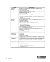
...compatible • Industry Leading Mixed Signal Technology • 18-bit stereo full-duplex Codec with status indicator LEDs on the back panel • Full device driver compatibility • ACPI support • Programmable transit threshold • Configuration EEPROM that contains the MAC...Operation : +5 o C to 90 % A-2 Specifications Storage : -10 o C to 80 % (No condensation) - Supports LAN wake capabilities Intel ® 82562ET physical layer interface device • Basic 10/100 Ethernet LAN connectivity • Supports RJ-45 connector with independent and variable sampling rate...
...compatible • Industry Leading Mixed Signal Technology • 18-bit stereo full-duplex Codec with status indicator LEDs on the back panel • Full device driver compatibility • ACPI support • Programmable transit threshold • Configuration EEPROM that contains the MAC...Operation : +5 o C to 90 % A-2 Specifications Storage : -10 o C to 80 % (No condensation) - Supports LAN wake capabilities Intel ® 82562ET physical layer interface device • Basic 10/100 Ethernet LAN connectivity • Supports RJ-45 connector with independent and variable sampling rate...


