
Product Guide
Page 5
Contents 1 Desktop Board Features Desktop Board Components 11 Processor ...13 System Memory 13 Integrated Graphics Subsystem 14 Intel® NM10 Express Chipset 14 Operating System Support 14 Onboard Audio Subsystem 14 Legacy Input/Output (I/O) Controller 16 LAN Subsystem 16 USB 2.0 Support 17 SATA Interface 17 Expandability...17 BIOS ...18 PCI Auto Configuration 18 Security Passwords 18 Power Management Features 18 ACPI ...19 Hardware Support 19 ENERGY STAR*, e-Standby, and ErP Compliance 22 Battery ...22 Real-Time Clock 22 2 Installing and Replacing Desktop Board Components...
Contents 1 Desktop Board Features Desktop Board Components 11 Processor ...13 System Memory 13 Integrated Graphics Subsystem 14 Intel® NM10 Express Chipset 14 Operating System Support 14 Onboard Audio Subsystem 14 Legacy Input/Output (I/O) Controller 16 LAN Subsystem 16 USB 2.0 Support 17 SATA Interface 17 Expandability...17 BIOS ...18 PCI Auto Configuration 18 Security Passwords 18 Power Management Features 18 ACPI ...19 Hardware Support 19 ENERGY STAR*, e-Standby, and ErP Compliance 22 Battery ...22 Real-Time Clock 22 2 Installing and Replacing Desktop Board Components...
Product Guide
Page 17
... USB 2.0 ports are compatible with USB 1.1 devices. Use a shielded cable that do not support USB 2.0. The SATA controller supports IDE and ACHI configuration and can support either a single PCI add-in card or a single- This may be required to accommodate operating systems that meets the requirements for a full-speed USB device. USB 2.0 Support The Desktop Board supports up and the LAN subsystem is operating. or dual-slot PCI riser card. 17 USB 1.1 devices will function normally at USB 1.1 speeds. NOTE Computer systems that support one PCI connector...
... USB 2.0 ports are compatible with USB 1.1 devices. Use a shielded cable that do not support USB 2.0. The SATA controller supports IDE and ACHI configuration and can support either a single PCI add-in card or a single- This may be required to accommodate operating systems that meets the requirements for a full-speed USB device. USB 2.0 Support The Desktop Board supports up and the LAN subsystem is operating. or dual-slot PCI riser card. 17 USB 1.1 devices will function normally at USB 1.1 speeds. NOTE Computer systems that support one PCI connector...

Product Guide
Page 30
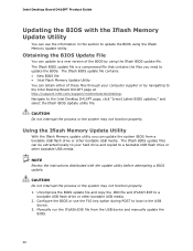
... SATA cables support the Serial ATA protocol. Reinstall and reconnect any parts you removed or disconnected to the drive (Figure 9, B). 30 For correct cable and drive function: 1. Attach the cable end without the lock to reach the DIMM sockets. 8. Replace the computer's cover and reconnect the AC power cord. Connecting SATA Drives The board has two SATA connectors each end of the socket. 6. Intel Desktop Board D410PT Product Guide Removing DIMMs To remove a DIMM, follow these steps: 1. Turn...
... SATA cables support the Serial ATA protocol. Reinstall and reconnect any parts you removed or disconnected to the drive (Figure 9, B). 30 For correct cable and drive function: 1. Attach the cable end without the lock to reach the DIMM sockets. 8. Replace the computer's cover and reconnect the AC power cord. Connecting SATA Drives The board has two SATA connectors each end of the socket. 6. Intel Desktop Board D410PT Product Guide Removing DIMMs To remove a DIMM, follow these steps: 1. Turn...

Product Guide
Page 38
... you confirm clearing the password. Turn off the computer. Replace the cover, plug in the event of a failed BIOS update. Press and Setup displays a pop-up screen requesting that the board is set to save the current values and exit Setup. 10. Setup displays the maintenance menu again. 9. Turn off all peripheral devices connected to boot. 7. Turn off the computer. Jumper Settings for the BIOS Setup Program Modes Jumper Setting Mode Normal (default) (1-2) Description The BIOS uses the current configuration and passwords for booting. Observe...
... you confirm clearing the password. Turn off the computer. Replace the cover, plug in the event of a failed BIOS update. Press and Setup displays a pop-up screen requesting that the board is set to save the current values and exit Setup. 10. Setup displays the maintenance menu again. 9. Turn off all peripheral devices connected to boot. 7. Turn off the computer. Jumper Settings for the BIOS Setup Program Modes Jumper Setting Mode Normal (default) (1-2) Description The BIOS uses the current configuration and passwords for booting. Observe...
Product Guide
Page 46
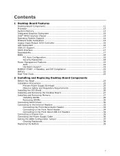
... hard drive and copied to update the BIOS. Intel Desktop Board D410PT Product Guide Updating the BIOS with the update utility before attempting a BIOS update. The Iflash BIOS update file contains: • New BIOS file • Intel Flash Memory Update Utility You can be extracted locally to your computer supplier or by using the Iflash Memory Update Utility. NOTE Review the instructions distributed with the Iflash Memory Update Utility You can use the F10 key option during POST to boot to the Intel Desktop Board D410PT page at http://support.intel.com/support/motherboards/desktop...
... hard drive and copied to update the BIOS. Intel Desktop Board D410PT Product Guide Updating the BIOS with the update utility before attempting a BIOS update. The Iflash BIOS update file contains: • New BIOS file • Intel Flash Memory Update Utility You can be extracted locally to your computer supplier or by using the Iflash Memory Update Utility. NOTE Review the instructions distributed with the Iflash Memory Update Utility You can use the F10 key option during POST to boot to the Intel Desktop Board D410PT page at http://support.intel.com/support/motherboards/desktop...
Product Guide
Page 5
Contents 1 Desktop Board Features Desktop Board Components 11 Processor ...13 System Memory 13 Integrated Graphics Subsystem 14 Intel® NM10 Express Chipset 14 Operating System Support 14 Onboard Audio Subsystem 14 Legacy Input/Output (I/O) Controller 16 LAN Subsystem 16 USB 2.0 Support 17 SATA Interface 17 Expandability...17 BIOS ...18 PCI Auto Configuration 18 Security Passwords 18 Power Management Features 18 ACPI ...19 Hardware Support 19 ENERGY STAR*, e-Standby, and ErP Compliance 22 Battery ...22 Real-Time Clock 22 2 Installing and Replacing Desktop Board Components...
Contents 1 Desktop Board Features Desktop Board Components 11 Processor ...13 System Memory 13 Integrated Graphics Subsystem 14 Intel® NM10 Express Chipset 14 Operating System Support 14 Onboard Audio Subsystem 14 Legacy Input/Output (I/O) Controller 16 LAN Subsystem 16 USB 2.0 Support 17 SATA Interface 17 Expandability...17 BIOS ...18 PCI Auto Configuration 18 Security Passwords 18 Power Management Features 18 ACPI ...19 Hardware Support 19 ENERGY STAR*, e-Standby, and ErP Compliance 22 Battery ...22 Real-Time Clock 22 2 Installing and Replacing Desktop Board Components...

Product Guide
Page 17
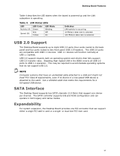
... dual-slot PCI riser card. 17 Expandability For system expansion, the Desktop Board provides one PCI connector that support one device per channel. Desktop Board Features Table 4 describes the LED states when the board is powered up to eight USB 2.0 ports (four ports routed to the back panel and four ports routed to USB 1.1 operation. SATA Interface The Desktop Board supports two SATA channels (3.0 Gb/s) that can operate in the BIOS reverts all USB 2.0 ports to two front panel USB 2.0 headers). Table 4. LAN Status LEDs LED Activity (A) Speed (B) LED...
... dual-slot PCI riser card. 17 Expandability For system expansion, the Desktop Board provides one PCI connector that support one device per channel. Desktop Board Features Table 4 describes the LED states when the board is powered up to eight USB 2.0 ports (four ports routed to the back panel and four ports routed to USB 1.1 operation. SATA Interface The Desktop Board supports two SATA channels (3.0 Gb/s) that can operate in the BIOS reverts all USB 2.0 ports to two front panel USB 2.0 headers). Table 4. LAN Status LEDs LED Activity (A) Speed (B) LED...

Product Guide
Page 30
... supporting one SATA drive. Remove the computer's cover. 5. Replace the computer's cover and reconnect the AC power cord. Observe the precautions in "Before You Begin" on the board (Figure 9, A). 3. Turn off the computer. 3. The DIMM pops out of the DIMM socket. For correct cable and drive function: 1. The included SATA cables support the Serial ATA protocol. Reinstall and reconnect any parts you removed or disconnected to the connector...
... supporting one SATA drive. Remove the computer's cover. 5. Replace the computer's cover and reconnect the AC power cord. Observe the precautions in "Before You Begin" on the board (Figure 9, A). 3. Turn off the computer. 3. The DIMM pops out of the DIMM socket. For correct cable and drive function: 1. The included SATA cables support the Serial ATA protocol. Reinstall and reconnect any parts you removed or disconnected to the connector...

Product Guide
Page 38
... power source (wall outlet or power adapter). 3. Intel Desktop Board D410PTL Product Guide Table 10. Replace the cover, plug in "Before You Begin" on the computer, and allow it to normal mode. 1. Turn off all peripheral devices connected to clear passwords. Clearing Passwords This procedure assumes that you confirm clearing the password. Place the jumper on pins 2-3 as shown below. 6. Jumper Settings for the BIOS Setup Program Modes Jumper Setting Mode Normal (default) (1-2) Description The BIOS uses the current configuration and passwords for booting...
... power source (wall outlet or power adapter). 3. Intel Desktop Board D410PTL Product Guide Table 10. Replace the cover, plug in "Before You Begin" on the computer, and allow it to normal mode. 1. Turn off all peripheral devices connected to clear passwords. Clearing Passwords This procedure assumes that you confirm clearing the password. Place the jumper on pins 2-3 as shown below. 6. Jumper Settings for the BIOS Setup Program Modes Jumper Setting Mode Normal (default) (1-2) Description The BIOS uses the current configuration and passwords for booting...

Product Guide
Page 46
...://www.intel.com/support/motherboards/desktop. NOTE Review the instructions distributed with the Iflash Memory Update Utility You can use the F10 key option during POST to boot to the USB device. 3. CAUTION Do not interrupt the process or the system may not function properly. Intel Desktop Board D410PTL Product Guide Updating the BIOS with the update utility before attempting a BIOS update. Manually run the IFLASH.EXE file from a bootable USB flash drive or other bootable USB media. 2. The Iflash BIOS update file is a compressed file...
...://www.intel.com/support/motherboards/desktop. NOTE Review the instructions distributed with the Iflash Memory Update Utility You can use the F10 key option during POST to boot to the USB device. 3. CAUTION Do not interrupt the process or the system may not function properly. Intel Desktop Board D410PTL Product Guide Updating the BIOS with the update utility before attempting a BIOS update. Manually run the IFLASH.EXE file from a bootable USB flash drive or other bootable USB media. 2. The Iflash BIOS update file is a compressed file...
Intel Desktop Board D410PT Technical Product Specification
Page 9
... Power 29 8. Wake-up Devices and Events 30 9. Chassis Fan Header 43 14. Thermal Considerations for Front Panel USB Header 48 13. LAN Connector LED Locations 23 4. LAN Connector LED States 23 5. Major Board Components 13 2. Connection Diagram for Components 54 25. Localized High Temperature Zones 53 16. Front Panel Header 46 21. Back Panel Audio Connectors 25 5. Back Panel Connectors 39 9. Serial Port Header (COM 1 and COM 2 43 13. Front Panel Wireless Activity LED Header 43 16. BIOS Configuration Jumper Settings 50 23. Connection...
... Power 29 8. Wake-up Devices and Events 30 9. Chassis Fan Header 43 14. Thermal Considerations for Front Panel USB Header 48 13. LAN Connector LED Locations 23 4. LAN Connector LED States 23 5. Major Board Components 13 2. Connection Diagram for Components 54 25. Localized High Temperature Zones 53 16. Front Panel Header 46 21. Back Panel Audio Connectors 25 5. Back Panel Connectors 39 9. Serial Port Header (COM 1 and COM 2 43 13. Front Panel Wireless Activity LED Header 43 16. BIOS Configuration Jumper Settings 50 23. Connection...
Intel Desktop Board D410PT Technical Product Specification
Page 10
... x BIOS Setup Program Function Keys 62 30. Supervisor and User Password Functions 68 33. Port 80h POST Codes 72 38. Safety Standards 77 40. EMC Regulations 83 42. BIOS Error Messages 70 36. Lead-Free Board Markings 82 41. Acceptable Drives/Media Types for BIOS Recovery 65 31. Boot Device Menu Options 67 32. BIOS Setup Program Menu Bar 62 29. Port 80h POST Code Ranges 71 37. Intel Desktop Board D410PT Technical Product Specification 27. Front-panel Power LED Blink Codes 70 35. Intel Desktop Board D410PT Environmental Specifications...
... x BIOS Setup Program Function Keys 62 30. Supervisor and User Password Functions 68 33. Port 80h POST Codes 72 38. Safety Standards 77 40. EMC Regulations 83 42. BIOS Error Messages 70 36. Lead-Free Board Markings 82 41. Acceptable Drives/Media Types for BIOS Recovery 65 31. Boot Device Menu Options 67 32. BIOS Setup Program Menu Bar 62 29. Port 80h POST Code Ranges 71 37. Intel Desktop Board D410PT Technical Product Specification 27. Front-panel Power LED Blink Codes 70 35. Intel Desktop Board D410PT Environmental Specifications...

Intel Desktop Board D410PT Technical Product Specification
Page 11
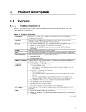
... Chipset Audio Internal Graphics 2+2 channel audio subsystem using Realtek* ALC662 high definition audio codec Onboard Intel® graphics subsystem with support for: • Integrated GMCH • Analog displays (VGA) Legacy I/O Control Peripheral Interfaces LAN Support BIOS Winbond W83627THG-I based Legacy I/O controller for hardware management, serial, and PS/2* ports • Eight USB 2.0 ports: ― Four back panel ports ― Four ports are implemented with two dual port internal headers for front panel cabling • Two Serial ATA (SATA) 3.0 Gb/s connectors (supporting IDE...
... Chipset Audio Internal Graphics 2+2 channel audio subsystem using Realtek* ALC662 high definition audio codec Onboard Intel® graphics subsystem with support for: • Integrated GMCH • Analog displays (VGA) Legacy I/O Control Peripheral Interfaces LAN Support BIOS Winbond W83627THG-I based Legacy I/O controller for hardware management, serial, and PS/2* ports • Eight USB 2.0 ports: ― Four back panel ports ― Four ports are implemented with two dual port internal headers for front panel cabling • Two Serial ATA (SATA) 3.0 Gb/s connectors (supporting IDE...
Intel Desktop Board D410PT Technical Product Specification
Page 48
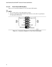
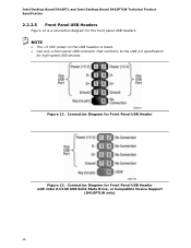
Connection Diagram for the front panel USB headers. Intel Desktop Board D410PT Technical Product Specification 2.2.2.5 Front Panel USB Headers Figure 12 is fused. • Use only a front panel USB connector that conforms to the USB 2.0 specification for high-speed USB devices. Figure 12. NOTE • The +5 VDC power on the USB headers is a connection diagram for Front Panel USB Header 48
Connection Diagram for the front panel USB headers. Intel Desktop Board D410PT Technical Product Specification 2.2.2.5 Front Panel USB Headers Figure 12 is fused. • Use only a front panel USB connector that conforms to the USB 2.0 specification for high-speed USB devices. Figure 12. NOTE • The +5 VDC power on the USB headers is a connection diagram for Front Panel USB Header 48

Intel Desktop Board D410PT Technical Product Specification
Page 62
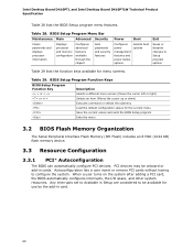
...a user turns on the system after adding a PCI card, the BIOS automatically configures interrupts, the I/O space, and other system resources. BIOS Setup Program Menu Bar Maintenance Main Advanced Security Clears passwords and displays processor information Displays processor and memory configuration Configures advanced features available through the chipset Sets passwords and security features Power Boot Configures power management features and power states options Selects boot options Exit Saves or discards changes to Setup program options Table 30 lists the function keys available...
...a user turns on the system after adding a PCI card, the BIOS automatically configures interrupts, the I/O space, and other system resources. BIOS Setup Program Menu Bar Maintenance Main Advanced Security Clears passwords and displays processor information Displays processor and memory configuration Configures advanced features available through the chipset Sets passwords and security features Power Boot Configures power management features and power states options Selects boot options Exit Saves or discards changes to Setup program options Table 30 lists the function keys available...
Intel Desktop Board D410PTL /D410PTLW Technical Product Specification
Page 7
... 11. Chassis Fan Header 41 14. Board Dimensions 49 16. ENERGY STAR Requirements 32 10. Connection Diagram for AC '97 Audio 42 18. SATA Connectors 41 15. Contents Figures 1. Fan Header Current Capability 50 vii Major Board Components 11 2. LAN Connector LED States 21 5. Front Panel Header 44 21. Front Panel Audio Header for Front Panel Header 44 12. Front Panel USB Header with Intel Z-U130 USB Solid-State Drive, or Compatible Device, Support (D410PTLW only)........ 46 14. Location of the BIOS Configuration Jumper Block...
... 11. Chassis Fan Header 41 14. Board Dimensions 49 16. ENERGY STAR Requirements 32 10. Connection Diagram for AC '97 Audio 42 18. SATA Connectors 41 15. Contents Figures 1. Fan Header Current Capability 50 vii Major Board Components 11 2. LAN Connector LED States 21 5. Front Panel Header 44 21. Front Panel Audio Header for Front Panel Header 44 12. Front Panel USB Header with Intel Z-U130 USB Solid-State Drive, or Compatible Device, Support (D410PTLW only)........ 46 14. Location of the BIOS Configuration Jumper Block...
Intel Desktop Board D410PTL /D410PTLW Technical Product Specification
Page 8
.... BIOS Setup Program Function Keys 60 30. Product Certification Markings 82 viii Intel Desktop Boards D410PTL and D410PTLW Environmental Specifications 57 28. Front-panel Power LED Blink Codes 68 35. Maximum Load Configuration Current and Power Results 56 27. AcceptableDrives/Media Types for Components 52 25. BIOS Beep Codes 67 34. Intel Desktop Board D410PTL and Intel Desktop Board D410PTLW Technical Product Specification 24. Safety Standards 75 40. EMC Regulations 81 42. Boot Device Menu Options 65 32. Port 80h POST Code...
.... BIOS Setup Program Function Keys 60 30. Product Certification Markings 82 viii Intel Desktop Boards D410PTL and D410PTLW Environmental Specifications 57 28. Front-panel Power LED Blink Codes 68 35. Maximum Load Configuration Current and Power Results 56 27. AcceptableDrives/Media Types for Components 52 25. BIOS Beep Codes 67 34. Intel Desktop Board D410PTL and Intel Desktop Board D410PTLW Technical Product Specification 24. Safety Standards 75 40. EMC Regulations 81 42. Boot Device Menu Options 65 32. Port 80h POST Code...
Intel Desktop Board D410PTL /D410PTLW Technical Product Specification
Page 9
... memory on a single DIMM (4 GB with two DIMMs) Passively cooled, Intel® NM10 Express Chipset 2+2 channel audio subsystem using Realtek* ALC662 high definition audio codec Onboard Intel® graphics subsystem with support for: • Integrated GMCH • Analog displays (VGA) Legacy I/O Control Peripheral Interfaces LAN Support BIOS Winbond W83627THG-I based Legacy I/O controller for hardware management, parallel, serial, and PS/2* ports • Eight USB 2.0 ports (D410PTL only): ― Four back panel ports ― Four ports are implemented with two dual port internal headers...
... memory on a single DIMM (4 GB with two DIMMs) Passively cooled, Intel® NM10 Express Chipset 2+2 channel audio subsystem using Realtek* ALC662 high definition audio codec Onboard Intel® graphics subsystem with support for: • Integrated GMCH • Analog displays (VGA) Legacy I/O Control Peripheral Interfaces LAN Support BIOS Winbond W83627THG-I based Legacy I/O controller for hardware management, parallel, serial, and PS/2* ports • Eight USB 2.0 ports (D410PTL only): ― Four back panel ports ― Four ports are implemented with two dual port internal headers...
Intel Desktop Board D410PTL /D410PTLW Technical Product Specification
Page 46
Connection Diagram for Front Panel USB Header with Intel Z-U130 USB Solid-State Drive, or Compatible Device Support (D410PTLW only) 46 Connection Diagram for Front Panel USB Header Figure 13. Figure 12. Intel Desktop Board D410PTL and Intel Desktop Board D410PTLW Technical Product Specification 2.2.2.5 Front Panel USB Headers Figure 12 is fused. • Use only a front panel USB connector that conforms to the USB 2.0 specification for the front panel USB headers. NOTE • The +5 VDC power on the USB headers is a connection diagram for high-speed USB devices.
Connection Diagram for Front Panel USB Header with Intel Z-U130 USB Solid-State Drive, or Compatible Device Support (D410PTLW only) 46 Connection Diagram for Front Panel USB Header Figure 13. Figure 12. Intel Desktop Board D410PTL and Intel Desktop Board D410PTLW Technical Product Specification 2.2.2.5 Front Panel USB Headers Figure 12 is fused. • Use only a front panel USB connector that conforms to the USB 2.0 specification for the front panel USB headers. NOTE • The +5 VDC power on the USB headers is a connection diagram for high-speed USB devices.
Intel Desktop Board D410PTL /D410PTLW Technical Product Specification
Page 60
... to be onboard or add-in card. 60 BIOS Setup Program Menu Bar Maintenance Main Advanced Security Clears passwords and displays processor information Displays processor and memory configuration Configures advanced features available through the chipset Sets passwords and security features Power Boot Configures power management features and power states options Selects boot options Exit Saves or discards changes to configure the system. Autoconfiguration lets a user insert or remove PCI cards without having to Setup program options Table 29 lists the function keys available for...
... to be onboard or add-in card. 60 BIOS Setup Program Menu Bar Maintenance Main Advanced Security Clears passwords and displays processor information Displays processor and memory configuration Configures advanced features available through the chipset Sets passwords and security features Power Boot Configures power management features and power states options Selects boot options Exit Saves or discards changes to configure the system. Autoconfiguration lets a user insert or remove PCI cards without having to Setup program options Table 29 lists the function keys available for...


