Instruction Manual
Page 7
... a message for transmit 7-6 D Recording 7-6 D Confirming a message for transmit 7-6 I Programming a memory name 7-7 I Sending a recorded message 7-8 D Transmit level setting 7-8 I Voice set mode 7-9 I Saving a voice memory into the CF card 7-10 D Saving the received audio memory 7-10 D Saving the TX memory 7-10 MEMORY OPERATION I Memory channels 8-2 I Memory channel selection 8-2 D Using the [Y]/[Z] keys 8-2 D Using the keypad 8-2 I Memory...
... a message for transmit 7-6 D Recording 7-6 D Confirming a message for transmit 7-6 I Programming a memory name 7-7 I Sending a recorded message 7-8 D Transmit level setting 7-8 I Voice set mode 7-9 I Saving a voice memory into the CF card 7-10 D Saving the received audio memory 7-10 D Saving the TX memory 7-10 MEMORY OPERATION I Memory channels 8-2 I Memory channel selection 8-2 D Using the [Y]/[Z] keys 8-2 D Using the keypad 8-2 I Memory...
Instruction Manual
Page 12
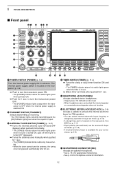
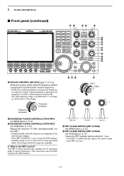
... does not function. See [KEY] on the rear panel. w TRANSMIT SWITCH [TRANSMIT] Selects transmitting or receiving. • The [TX] indicator lights red while transmitting and the [RX] indicator lights green when the squelch is available for your convenience. (p. 4-8) (dot...o !0 !1 !2 !3 q w e r t y u !4 !5 !6 !7 !8 q POWER SWITCH [POWER] (p. 3-2) Turn the internal power supply ON in use. ➥ Enters timer set mode. (p. 4-12) • 4-channel memory keyer is open. The internal power supply switch is located on the rear panel. (p. 3-2) ➥ Push to turn the transceiver...
... does not function. See [KEY] on the rear panel. w TRANSMIT SWITCH [TRANSMIT] Selects transmitting or receiving. • The [TX] indicator lights red while transmitting and the [RX] indicator lights green when the squelch is available for your convenience. (p. 4-8) (dot...o !0 !1 !2 !3 q w e r t y u !4 !5 !6 !7 !8 q POWER SWITCH [POWER] (p. 3-2) Turn the internal power supply ON in use. ➥ Enters timer set mode. (p. 4-12) • 4-channel memory keyer is open. The internal power supply switch is located on the rear panel. (p. 3-2) ➥ Push to turn the transceiver...
Instruction Manual
Page 15
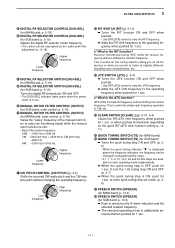
When a transverter is in split oper- Select "P. useful for scanning. (p. 9-3) #0 TRANSMIT INDICATOR [TX] (for MAIN band) #1 TRANSMIT INDICATOR [TX] (for SUB band) Lights red while transmitting. • SUB band's [TX] indicator lights only when in use, this [ANT] does not function and 'TRV' appears. ➥ ...; Turns the 1⁄4-speed tuning function ON and OFF in SSB data, CW, RTTY and PSK modes. (p. 3-6) • 1⁄4 function sets dial rotation to 1⁄4 of normal speed for fine tuning. ➥ Switches between 0.1 to produce a constant audio output level, even when the...
When a transverter is in split oper- Select "P. useful for scanning. (p. 9-3) #0 TRANSMIT INDICATOR [TX] (for MAIN band) #1 TRANSMIT INDICATOR [TX] (for SUB band) Lights red while transmitting. • SUB band's [TX] indicator lights only when in use, this [ANT] does not function and 'TRV' appears. ➥ ...; Turns the 1⁄4-speed tuning function ON and OFF in SSB data, CW, RTTY and PSK modes. (p. 3-6) • 1⁄4 function sets dial rotation to 1⁄4 of normal speed for fine tuning. ➥ Switches between 0.1 to produce a constant audio output level, even when the...

Instruction Manual
Page 17
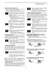
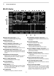
...signal until cancelling the record when pushed for 1 sec. %6 TRANSMIT FREQUENCY CHECK SWITCH [XFC] (p. 6-6) Monitors the transmit frequency (including ∂TX frequency offset) when pushed and held during split frequency operation. • While pushing this switch momentarily to stops recording. • The memory records...mini spectrum scope screen ON and OFF. • The mini spectrum scope screen can be displayed with another screen, such as memory or set mode menu screen when pushed for 1 sec. • Push this switch, the transmit frequency can be changed with the main dial, ...
...signal until cancelling the record when pushed for 1 sec. %6 TRANSMIT FREQUENCY CHECK SWITCH [XFC] (p. 6-6) Monitors the transmit frequency (including ∂TX frequency offset) when pushed and held during split frequency operation. • While pushing this switch momentarily to stops recording. • The memory records...mini spectrum scope screen ON and OFF. • The mini spectrum scope screen can be displayed with another screen, such as memory or set mode menu screen when pushed for 1 sec. • Push this switch, the transmit frequency can be changed with the main dial, ...
Instruction Manual
Page 20
... CLEAR] for SUB band; The PBT function electronically modifies the IF passband width to decrease the frequency. p. 5-12) Clears the PBT settings when pushed for SUB band; p. 5-12) *2 PASSBAND TUNING CONTROLS [TWIN PBT] (for 1 sec. • The [PBT CLEAR...(for the PBT function. 1 PANEL DESCRIPTION I Front panel (continued) *0 *1 *3 *4 *2 *5 *7 *8 *6 *9 (0 (1 (2 (3 (4 *0 RIT/∂TX CONTROL [RIT/∂TX] (pgs. 5-10, 6-4) Shifts the receive and/or transmit frequency without changing the transmit and/or receive frequency. • Rotate the control clockwise to increase...
... CLEAR] for SUB band; The PBT function electronically modifies the IF passband width to decrease the frequency. p. 5-12) Clears the PBT settings when pushed for SUB band; p. 5-12) *2 PASSBAND TUNING CONTROLS [TWIN PBT] (for 1 sec. • The [PBT CLEAR...(for the PBT function. 1 PANEL DESCRIPTION I Front panel (continued) *0 *1 *3 *4 *2 *5 *7 *8 *6 *9 (0 (1 (2 (3 (4 *0 RIT/∂TX CONTROL [RIT/∂TX] (pgs. 5-10, 6-4) Shifts the receive and/or transmit frequency without changing the transmit and/or receive frequency. • Rotate the control clockwise to increase...
Instruction Manual
Page 21
... FILTER CONTROL [NOTCH] (for SUB band; or when pushed momentarily, depending on off-frequency or when you on the quick RIT/∂TX clear function setting (p. 1217). (5 QUICK TUNING SWITCH [TS] (for MAIN band) (6 QUICK TUNING SWITCH [TS] (for SUB band) ➥ ... differentsounding voice characteristics, etc. (3 ∂TX SWITCH [∂TX] (p. 6-4) ➥ Turns the ∂TX function ON and OFF when pushed. • Use [RIT/∂TX] control to vary the ∂TX frequency. ➥ Adds the ∂TX shift frequency to enter quick tuning step set mode. (p. 36) (7 SPEECH SWITCH ...
... FILTER CONTROL [NOTCH] (for SUB band; or when pushed momentarily, depending on off-frequency or when you on the quick RIT/∂TX clear function setting (p. 1217). (5 QUICK TUNING SWITCH [TS] (for MAIN band) (6 QUICK TUNING SWITCH [TS] (for SUB band) ➥ ... differentsounding voice characteristics, etc. (3 ∂TX SWITCH [∂TX] (p. 6-4) ➥ Turns the ∂TX function ON and OFF when pushed. • Use [RIT/∂TX] control to vary the ∂TX frequency. ➥ Adds the ∂TX shift frequency to enter quick tuning step set mode. (p. 36) (7 SPEECH SWITCH ...
Instruction Manual
Page 24
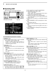
... (p. 3-10) Shows the signal strength while receiving. Shows the relative output power, SWR, ALC or compression levels while transmitting. !0 TX INDICATOR Indicates the frequency readout for transmit. !8 MULTI-FUNCTION SCREEN Shows the screens for IF shift operation. w MODE INDICATOR Shows the ... multi-function digital meter, spectrum scope, voice recorder, memory channel, scan, memory keyer, RTTY decoder, PSK decoder, IF filter selection or set as a select memory channel. !5 MEMORY CHANNEL READOUTS ➥ Shows the selected memory channel contents in VFO mode. ➥ Shows the ...
... (p. 3-10) Shows the signal strength while receiving. Shows the relative output power, SWR, ALC or compression levels while transmitting. !0 TX INDICATOR Indicates the frequency readout for transmit. !8 MULTI-FUNCTION SCREEN Shows the screens for IF shift operation. w MODE INDICATOR Shows the ... multi-function digital meter, spectrum scope, voice recorder, memory channel, scan, memory keyer, RTTY decoder, PSK decoder, IF filter selection or set as a select memory channel. !5 MEMORY CHANNEL READOUTS ➥ Shows the selected memory channel contents in VFO mode. ➥ Shows the ...

Instruction Manual
Page 35
...Regulated 8 V output. Input impedance Input voltage : More than 10 kΩ : 2 to 0.8 V Output current : Less than 20 mA Input current (Tx) : Less than 10 mA 2 GND Same as ACC 1 pin 2. 3 SEND Same as ACC 1 pin 8. 6 TRV Activates [X-VERTER] input/output ...when "HIGH" voltage is applied. When grounded, transmits. Output current : Max. 1 A Connected in default settings. (see notes below) Output Output impedance level : 4.7 kΩ : 100-300 mV rms 6 SQLS Squelch output. SPECIFICATIONS Output voltage Output current : ...
...Regulated 8 V output. Input impedance Input voltage : More than 10 kΩ : 2 to 0.8 V Output current : Less than 20 mA Input current (Tx) : Less than 10 mA 2 GND Same as ACC 1 pin 2. 3 SEND Same as ACC 1 pin 8. 6 TRV Activates [X-VERTER] input/output ...when "HIGH" voltage is applied. When grounded, transmits. Output current : Max. 1 A Connected in default settings. (see notes below) Output Output impedance level : 4.7 kΩ : 100-300 mV rms 6 SQLS Squelch output. SPECIFICATIONS Output voltage Output current : ...
Instruction Manual
Page 50
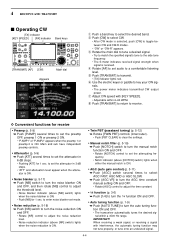
...10149; Rotate [TWIN PBT] controls (inner/outer). • Push [PBT CLEAR] to clear the settings. • Audio tone control (p. 12-4) ➥ Push [F-7•SET] then [F-1•LEVEL] to set to transmit. • [TX] indicator lights red. y Speak into the microphone at your normal voice level. • Adjust the ... to turn the auto or manual notch function ON and OFF. • Rotate [NOTCH] control to set mode. e Rotate the main dial to receive. 4 RECEIVE AND TRANSMIT I Operating SSB [MIC] [TX] indicator [RX] indicator Band keys [TRANSMIT] [AF] [SSB] Main dial Appears q Push a ...
...10149; Rotate [TWIN PBT] controls (inner/outer). • Push [PBT CLEAR] to clear the settings. • Audio tone control (p. 12-4) ➥ Push [F-7•SET] then [F-1•LEVEL] to set to transmit. • [TX] indicator lights red. y Speak into the microphone at your normal voice level. • Adjust the ... to turn the auto or manual notch function ON and OFF. • Rotate [NOTCH] control to set mode. e Rotate the main dial to receive. 4 RECEIVE AND TRANSMIT I Operating SSB [MIC] [TX] indicator [RX] indicator Band keys [TRANSMIT] [AF] [SSB] Main dial Appears q Push a ...
Instruction Manual
Page 52
...tune onto an undesired signal. 4-4 tion ON and OFF. • The transceiver automatically tunes the desired sig- IMPORTANT! 4 RECEIVE AND TRANSMIT I Operating CW [TX] indicator [KEY SPEED] [RX] indicator Band keys [TRANSMIT] [AF] [CW] Main dial Appears q Push a band key to receive. w Push [... ➥ Push [NR] switch to turn the 1⁄4 function ON and OFF. • Auto tuning function (p. 1-9) ➥ Push [AUTO TUNE] to set the attenuator in 6 dB steps. • Pushing [ATT] for 1 sec. to adjust the noise reduction level. • Noise reduction indicator (above [NOTCH] ...
...tune onto an undesired signal. 4-4 tion ON and OFF. • The transceiver automatically tunes the desired sig- IMPORTANT! 4 RECEIVE AND TRANSMIT I Operating CW [TX] indicator [KEY SPEED] [RX] indicator Band keys [TRANSMIT] [AF] [CW] Main dial Appears q Push a band key to receive. w Push [... ➥ Push [NR] switch to turn the 1⁄4 function ON and OFF. • Auto tuning function (p. 1-9) ➥ Push [AUTO TUNE] to set the attenuator in 6 dB steps. • Pushing [ATT] for 1 sec. to adjust the noise reduction level. • Noise reduction indicator (above [NOTCH] ...
Instruction Manual
Page 59
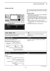
...the default condition or value. to select keyer set mode. steps can be selected. (default: 1:1:3.0) This item sets the rise time of the transmitted CW envelope. • About rise time Tx Key action Rx • 2, 4, 6 or 8 msec. t Push [EXIT/SET] twice to select memory keyer screen. Keying weight... sending CW using the main dial. • Push [F-4•DEF] for 1 sec. in 0.1 steps) can be selected. (default: 4 msec.) Tx output power Set Tx power level 0 Rise time Time 4-11 to 60 sec. can be adjusted with [KEY SPEED] only. • 1:1:2.8 to select the desired...
...the default condition or value. to select keyer set mode. steps can be selected. (default: 1:1:3.0) This item sets the rise time of the transmitted CW envelope. • About rise time Tx Key action Rx • 2, 4, 6 or 8 msec. t Push [EXIT/SET] twice to select memory keyer screen. Keying weight... sending CW using the main dial. • Push [F-4•DEF] for 1 sec. in 0.1 steps) can be selected. (default: 4 msec.) Tx output power Set Tx power level 0 Rise time Time 4-11 to 60 sec. can be adjusted with [KEY SPEED] only. • 1:1:2.8 to select the desired...

Instruction Manual
Page 64
...on the keyboard to transmit the selected memory and press [F12] again to return to select the desired condition as the "AUTO TX/RX" setting when no keyboard is connected, the selected memory contents will be transmitted immediately. • When a keyboard is connected, the ...] on the connected keyboard is connected. 4-16 D Automatic transmission/reception setting [F-6•AUTO TX] [EXIT/SET] [F-7•RT1..RT8] q During RTTY mode operation, push [F-3•DECODE] to select RTTY memory screen. w Push [F-4•TX MEM] to select RTTY memory screen, then push [F-6•EDIT] to...
...on the keyboard to transmit the selected memory and press [F12] again to return to select the desired condition as the "AUTO TX/RX" setting when no keyboard is connected, the selected memory contents will be transmitted immediately. • When a keyboard is connected, the ...] on the connected keyboard is connected. 4-16 D Automatic transmission/reception setting [F-6•AUTO TX] [EXIT/SET] [F-7•RT1..RT8] q During RTTY mode operation, push [F-3•DECODE] to select RTTY memory screen. w Push [F-4•TX MEM] to select RTTY memory screen, then push [F-6•EDIT] to...

Instruction Manual
Page 65
...;DEL] deletes a character and [F-4•SPACE] inserts a space. r Push [F-5•Ω ≈] to set the contents and exit RTTY memory edit screen. 4-17 e Push [F-7•RT1..RT8] to several times to ...on the rear panel, the RTTY memory contents can also be edited. w Push [F-4•TX MEM] to select RTTY memory screen, then push [F-6•EDIT] to select RTTY memory ...DE ICOM ICOM ICOM K↵ RT7 RIG&ANT ↵MY TRANSCEIVER IS IC-7800 & ANTENNA IS A 3-ELEMENT TRIBAND YAGI.↵ RT8 EQUIP. ↵MY RTTY EQUIPMENT IS INTERNAL FSK UNIT & DEMODULATOR OF THE IC-7800.↵...
...;DEL] deletes a character and [F-4•SPACE] inserts a space. r Push [F-5•Ω ≈] to set the contents and exit RTTY memory edit screen. 4-17 e Push [F-7•RT1..RT8] to several times to ...on the rear panel, the RTTY memory contents can also be edited. w Push [F-4•TX MEM] to select RTTY memory screen, then push [F-6•EDIT] to select RTTY memory ...DE ICOM ICOM ICOM K↵ RT7 RIG&ANT ↵MY TRANSCEIVER IS IC-7800 & ANTENNA IS A 3-ELEMENT TRIBAND YAGI.↵ RT8 EQUIP. ↵MY RTTY EQUIPMENT IS INTERNAL FSK UNIT & DEMODULATOR OF THE IC-7800.↵...

Instruction Manual
Page 67
...required by the receiving station. • ON : Inserts FIGS. • OFF : Does not insert FIGS. Set the text color in the TX buffer screen. • The color is set in RGB format. • The set color is indicated in the box beside the RGB scale. • Push [F-3•Ω ≈] to select... R (Red), G (Green) and B (Blue), and then rotate the main dial to set mode (continued) Explicitly ...
...required by the receiving station. • ON : Inserts FIGS. • OFF : Does not insert FIGS. Set the text color in the TX buffer screen. • The color is set in RGB format. • The set color is indicated in the box beside the RGB scale. • Push [F-3•Ω ≈] to select... R (Red), G (Green) and B (Blue), and then rotate the main dial to set mode (continued) Explicitly ...

Instruction Manual
Page 72
... [F-7•1-4/5-8] to select memory bank then push one of the memory are set characters can be sent using the edit menu. r Push [F-6•AUTO TX] several times to receive after the transmission. • AUTO TX : Automatically transmits the selected memory. 4 RECEIVE AND TRANSMIT D PSK memory...memory. e Push [F-7•PT1..PT8] several times to select the desired condition, as the "AUTO TX/RX" setting when no keyboard is pressed, depending on auto transmission/reception setting (see below). • The transmission date, time, reception date and/or time may be transmitted ...
... [F-7•1-4/5-8] to select memory bank then push one of the memory are set characters can be sent using the edit menu. r Push [F-6•AUTO TX] several times to receive after the transmission. • AUTO TX : Automatically transmits the selected memory. 4 RECEIVE AND TRANSMIT D PSK memory...memory. e Push [F-7•PT1..PT8] several times to select the desired condition, as the "AUTO TX/RX" setting when no keyboard is pressed, depending on auto transmission/reception setting (see below). • The transmission date, time, reception date and/or time may be transmitted ...
Instruction Manual
Page 73
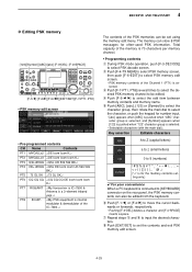
w Push [F-4•TX MEM] to select PSK memory ... select the desired PSK memory channel to [KEYBOARD] connector on the rear panel, the PSK memory contents can store 8 PSK messages for the memory contents set- r Push [F-5•Ω ≈] to input the desired characters. y Push [F-1•Ω] or [F-2•≈] to 9 (numbers) ! # $ < > ( % ) [ & ¥ ] { } ? ...DE Icom Icom Icom K↵ PT7 RIG&ANT ↵My transceiver is IC-7800 & Antenna is a 3-element triband yagi.↵ PT8 EQUIP. ↵My PSK equipment is internal modulator & demodulator of the IC-7800.↵...
w Push [F-4•TX MEM] to select PSK memory ... select the desired PSK memory channel to [KEYBOARD] connector on the rear panel, the PSK memory contents can store 8 PSK messages for the memory contents set- r Push [F-5•Ω ≈] to input the desired characters. y Push [F-1•Ω] or [F-2•≈] to 9 (numbers) ! # $ < > ( % ) [ & ¥ ] { } ? ...DE Icom Icom Icom K↵ PT7 RIG&ANT ↵My transceiver is IC-7800 & Antenna is a 3-element triband yagi.↵ PT8 EQUIP. ↵My PSK equipment is internal modulator & demodulator of the IC-7800.↵...

Instruction Manual
Page 75
... select R (Red), G (Green) and B (Blue), and then rotate the main dial to set the ratio from 0 to 255. Set the text color in the TX buffer screen. • The color is set in RGB format. • The set color is indicated in the box beside the RGB scale. • Push [F-3•Ω ≈...;] to select R (Red), G (Green) and B (Blue), and then rotate the main dial to set the ratio...
... select R (Red), G (Green) and B (Blue), and then rotate the main dial to set the ratio from 0 to 255. Set the text color in the TX buffer screen. • The color is set in RGB format. • The set color is indicated in the box beside the RGB scale. • Push [F-3•Ω ≈...;] to select R (Red), G (Green) and B (Blue), and then rotate the main dial to set the ratio...
Instruction Manual
Page 77
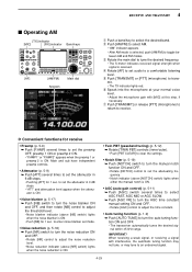
...[AGC] control to adjust the time constant. • Auto tuning function (p. 1-9) ➥ Push [AUTO TUNE] to an undesired signal. 4-29 to set audio to set the attenuator in 6 dB steps. • Pushing [ATT] for receive • Preamp (p. 5-9) ➥ Push [P.AMP] several times to select AGC...blanker (p. 5-17) ➥ Push [NB] switch to turn the manual notch function ON and OFF. • Rotate [NOTCH] control to set the attenuating fre- I Operating AM [TX] indicator [MIC] [RX] indicator Band keys [AF] [AM/FM] Main dial Appears 4 RECEIVE AND TRANSMIT q Push a band key to...
...[AGC] control to adjust the time constant. • Auto tuning function (p. 1-9) ➥ Push [AUTO TUNE] to an undesired signal. 4-29 to set audio to set the attenuator in 6 dB steps. • Pushing [ATT] for receive • Preamp (p. 5-9) ➥ Push [P.AMP] several times to select AGC...blanker (p. 5-17) ➥ Push [NB] switch to turn the manual notch function ON and OFF. • Rotate [NOTCH] control to set the attenuating fre- I Operating AM [TX] indicator [MIC] [RX] indicator Band keys [AF] [AM/FM] Main dial Appears 4 RECEIVE AND TRANSMIT q Push a band key to...
Instruction Manual
Page 79
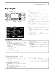
...[FILTER] several times to a comfortable listening level. tween FM and AM modes. mit. • The TX indicator lights red. u Push [TRANSMIT] or release [PTT] (microphone) to return to trans- to set audio to set the preamp OFF, preamp 1 ON or preamp 2 ON. • "P.AMP1" or "P.AMP2" appears ... (p. 6-4) ➥ Push [MONI] to toggle be- 4 RECEIVE AND TRANSMIT I Operating FM [TX] indicator [MIC] [RX] indicator Band keys [FILTER] [AF] [AM/FM] Main dial Appears q Push a band key to set mode. y Speak into the microphone at your normal voice level. • Adjust the microphone gain ...
...[FILTER] several times to a comfortable listening level. tween FM and AM modes. mit. • The TX indicator lights red. u Push [TRANSMIT] or release [PTT] (microphone) to return to trans- to set audio to set the preamp OFF, preamp 1 ON or preamp 2 ON. • "P.AMP1" or "P.AMP2" appears ... (p. 6-4) ➥ Push [MONI] to toggle be- 4 RECEIVE AND TRANSMIT I Operating FM [TX] indicator [MIC] [RX] indicator Band keys [FILTER] [AF] [AM/FM] Main dial Appears q Push a band key to set mode. y Speak into the microphone at your normal voice level. • Adjust the microphone gain ...

Instruction Manual
Page 80
...50 tones from the receive frequency by an offset frequency. q Select FM mode. e Push [F-1•Y] or [F-2•Z] to select the default setting. t Set the receive frequency (repeater output fre- w Push [TONE] for 1 sec. to select REPEATER TONE item. A repeater can be accessed using... lights and " " appears on the LCD. • Shifted transmit frequency and "TX" appear in advance. For accessing a repeater which requires a repeater tone, set the repeater tone frequency in tone frequency set in the sub band. • The transmit frequency can be monitored while pushing [...
...50 tones from the receive frequency by an offset frequency. q Select FM mode. e Push [F-1•Y] or [F-2•Z] to select the default setting. t Set the receive frequency (repeater output fre- w Push [TONE] for 1 sec. to select REPEATER TONE item. A repeater can be accessed using... lights and " " appears on the LCD. • Shifted transmit frequency and "TX" appear in advance. For accessing a repeater which requires a repeater tone, set the repeater tone frequency in tone frequency set in the sub band. • The transmit frequency can be monitored while pushing [...


