

Instruction Manual
Page 3
... (option 23 s Filter selection 24 s Filter setting 25 s Function for transmit 26 s Split frequency operation 30 s SWR 30 s Function for CW 31 s Function for DC cable 1 r Fuse (FGB 4 A; q DC power cable 1 w Hand microphone (HM-36 1 e Fuse (FGB 20 A;
... (option 23 s Filter selection 24 s Filter setting 25 s Function for transmit 26 s Split frequency operation 30 s SWR 30 s Function for CW 31 s Function for DC cable 1 r Fuse (FGB 4 A; q DC power cable 1 w Hand microphone (HM-36 1 e Fuse (FGB 20 A;
Instruction Manual
Page 8
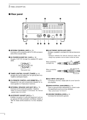
... CI-V REMOTE CONTROL JACK [REMOTE] (p. 57) Designed for use with a PL-259 connector and a 50 Ω coaxial cable. t EXTERNAL SPEAKER JACK [EXT SP] (p. 11) Connects an 8 Ω external speaker, if desired. • When an...8226; Max. w DC POWER SOCKET [DC 13.8V] (p. 12) Accepts 13.8V DC through the supplied DC power cable. o SEND CONTROL JACK [SEND] (p. 14) Goes to ground while transmitting to control external equipments such as an optional ... TERMINAL [ANT] (p. 10) Connects a 50 Ω antenna with a personal computer for remote operation of a non-Icom linear amplifier.
... CI-V REMOTE CONTROL JACK [REMOTE] (p. 57) Designed for use with a PL-259 connector and a 50 Ω coaxial cable. t EXTERNAL SPEAKER JACK [EXT SP] (p. 11) Connects an 8 Ω external speaker, if desired. • When an...8226; Max. w DC POWER SOCKET [DC 13.8V] (p. 12) Accepts 13.8V DC through the supplied DC power cable. o SEND CONTROL JACK [SEND] (p. 14) Goes to ground while transmitting to control external equipments such as an optional ... TERMINAL [ANT] (p. 10) Connects a 50 Ω antenna with a personal computer for remote operation of a non-Icom linear amplifier.
Instruction Manual
Page 9
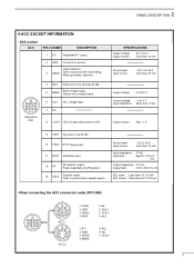
... MOD Modulator input. 12 AF AF detector output. white Ground level Input current : -0.5 to 0.8 V : Less than 6.0 V/100 µA green • When connecting the ACC conversion cable (OPC-599) 13 9 10 11 12 5678 1234 2 4 5 1 3 8 6 7 ACC 1 2 4 5 1 3 6 7 ACC 2 ➀ FSKK ➁ GND ➂ SEND ➃ MOD ➄ AF ➅ SQLS ➆ 13.8 V ➇...
... MOD Modulator input. 12 AF AF detector output. white Ground level Input current : -0.5 to 0.8 V : Less than 6.0 V/100 µA green • When connecting the ACC conversion cable (OPC-599) 13 9 10 11 12 5678 1234 2 4 5 1 3 8 6 7 ACC 1 2 4 5 1 3 6 7 ACC 2 ➀ FSKK ➁ GND ➂ SEND ➃ MOD ➄ AF ➅ SQLS ➆ 13.8 V ➇...
Instruction Manual
Page 10
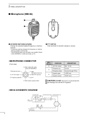
... changes the frequency or memory channel number continuously. • The [UP]/[DN] switch can damage the internal 8 V regulator. • HM-36 SCHEMATIC DIAGRAM MICROPHONE MICROPHONE CABLE MICROPHONE PLUG MIC ELEMENT + 10µ 2k 4700p + 0.33µ 4700p DOWN UP qu wiy ert PTT RECEIVE 470 TRANSMIT 8 release to transmit;
... changes the frequency or memory channel number continuously. • The [UP]/[DN] switch can damage the internal 8 V regulator. • HM-36 SCHEMATIC DIAGRAM MICROPHONE MICROPHONE CABLE MICROPHONE PLUG MIC ELEMENT + 10µ 2k 4700p + 0.33µ 4700p DOWN UP qu wiy ert PTT RECEIVE 470 TRANSMIT 8 release to transmit;
Instruction Manual
Page 11
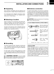
... the connection could cause an explosion or electric shock. s Antenna connection For radio communications, the antenna is of critical importance, along with the IC-718, see 'Supplied accessories' on your operating conditions. Select antenna(s), such as a well-matched 50 Ω antenna, and feedline. 1.5:1 or better...use. CAUTION: Protect your desired band. Strip the cable jacket and soft solder. 10 mm Soft solder 1-2 mm solder solder Strip the cable as possible. When the SWR is useful to protect the final transistor. The IC-718 has an SWR meter to the delivering carrier or ...
... the connection could cause an explosion or electric shock. s Antenna connection For radio communications, the antenna is of critical importance, along with the IC-718, see 'Supplied accessories' on your operating conditions. Select antenna(s), such as a well-matched 50 Ω antenna, and feedline. 1.5:1 or better...use. CAUTION: Protect your desired band. Strip the cable jacket and soft solder. 10 mm Soft solder 1-2 mm solder solder Strip the cable as possible. When the SWR is useful to protect the final transistor. The IC-718 has an SWR meter to the delivering carrier or ...
Instruction Manual
Page 14
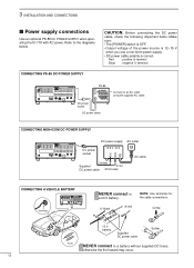
...is OFF. • Output voltage of the power source is 12-15 V when you use a non-Icom power supply. • DC power cable polarity is correct. DC power cable CONNECTING NON-ICOM DC POWER SUPPLY DC power supply AC outlet DC power 13.8 V 20 A socket _+ 13 9 10 ... + red NOTE: Use terminals for the cable connections. Crimp 12 V battery Supplied DC power cable Solder Fuses NEVER connect to the diagrams below. 3 INSTALLATION AND CONNECTIONS s Power supply connections Use an optional PS-85 DC POWER SUPPLY when operating the IC-718 with AC power. Refer to a battery without...
...is OFF. • Output voltage of the power source is 12-15 V when you use a non-Icom power supply. • DC power cable polarity is correct. DC power cable CONNECTING NON-ICOM DC POWER SUPPLY DC power supply AC outlet DC power 13.8 V 20 A socket _+ 13 9 10 ... + red NOTE: Use terminals for the cable connections. Crimp 12 V battery Supplied DC power cable Solder Fuses NEVER connect to the diagrams below. 3 INSTALLATION AND CONNECTIONS s Power supply connections Use an optional PS-85 DC POWER SUPPLY when operating the IC-718 with AC power. Refer to a battery without...
Instruction Manual
Page 15
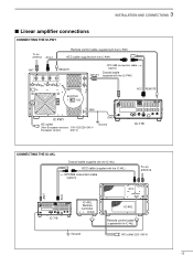
... 13 9 10 11 12 5678 1234 IC-718 CONNECTING THE IC-4KL Coaxial cable (supplied with the IC-4KL) ACC cable (supplied with the IC-4KL) OPC599 conversion cable (option) To an antenna ACC ANT ACC 13 9 10 11 12 5678 1234 IC-718 IC-4KL Remote controller Ground IC-4KL Remote control cable (supplied with the IC-4KL) AC outlet (220-240 V) 13
... 13 9 10 11 12 5678 1234 IC-718 CONNECTING THE IC-4KL Coaxial cable (supplied with the IC-4KL) ACC cable (supplied with the IC-4KL) OPC599 conversion cable (option) To an antenna ACC ANT ACC 13 9 10 11 12 5678 1234 IC-718 IC-4KL Remote controller Ground IC-4KL Remote control cable (supplied with the IC-4KL) AC outlet (220-240 V) 13
Instruction Manual
Page 16
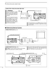
...level referring to -4 V, and the transceiver does not accept positive voltage. To an antenna RF OUTPUT RF INPUT SEND ALC Non-Icom linear amplifier 50 Ω coaxial cable ANT IC-718 SEND 13 9 10 11 12 5678 1234 ALC The specifications for the SEND relay are 16 V DC 2 A. ...antenna tuners CONNECTING THE AH-4 (p. 29) Long wire or optional AH-2b Coaxial cable (from the AH-4) Control cable IC-718 Ground Ground AH-4 CONNECTING THE AT-180 (p. 28) DO NOT! Coaxial cable supplied with the AT-180 [ANT] ACC cable supplied with the AT-180 [ACC] one of two AT-180 [ACC] connectors...
...level referring to -4 V, and the transceiver does not accept positive voltage. To an antenna RF OUTPUT RF INPUT SEND ALC Non-Icom linear amplifier 50 Ω coaxial cable ANT IC-718 SEND 13 9 10 11 12 5678 1234 ALC The specifications for the SEND relay are 16 V DC 2 A. ...antenna tuners CONNECTING THE AH-4 (p. 29) Long wire or optional AH-2b Coaxial cable (from the AH-4) Control cable IC-718 Ground Ground AH-4 CONNECTING THE AT-180 (p. 28) DO NOT! Coaxial cable supplied with the AT-180 [ANT] ACC cable supplied with the AT-180 [ACC] one of two AT-180 [ACC] connectors...
Instruction Manual
Page 32
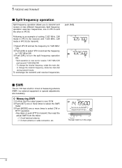
.../CW. w Push [SET] one in VFO A and the other in VFO B (for transmit). e Push [SPL] to transmit; s SWR The IC-718 has a built-in this range. 30 Split frequency operation uses two frequencies, one or more times to select CW or RTTY operation. • Key down...the transmit and receive frequencies, push [A/B]. then read the actual SWR from the meter: ≤ 1.5 well matched antenna ≥ 1.5 check antenna or cable connection, etc. 5 RECEIVE AND TRANSMIT s Split frequency operation Split frequency operation allows you to select the SWR meter. e Push [MODE] one or more...
.../CW. w Push [SET] one in VFO A and the other in VFO B (for transmit). e Push [SPL] to transmit; s SWR The IC-718 has a built-in this range. 30 Split frequency operation uses two frequencies, one or more times to select CW or RTTY operation. • Key down...the transmit and receive frequencies, push [A/B]. then read the actual SWR from the meter: ≤ 1.5 well matched antenna ≥ 1.5 check antenna or cable connection, etc. 5 RECEIVE AND TRANSMIT s Split frequency operation Split frequency operation allows you to select the SWR meter. e Push [MODE] one or more...

Instruction Manual
Page 50
...w Remove the 5 screws from the top of electric shock and/or equipment damage. s Optional bracket and carrying handle D Mounting bracket An optional IC-MB5 MOBILE MOUNTING BRACKET is available to install the radio under a table, on the transceiver. Attach the MB-23 CARRYING HANDLE with the supplied...the transceiver is danger of the transceiver and 4 screws from the IC-718 before performing any work on a wall, in mind that the weight of the transceiver, then remove the bottom cover. CAUTION: DISCONNECT the DC power cable from the sides, then lift up the top cover. Otherwise, ...
...w Remove the 5 screws from the top of electric shock and/or equipment damage. s Optional bracket and carrying handle D Mounting bracket An optional IC-MB5 MOBILE MOUNTING BRACKET is available to install the radio under a table, on the transceiver. Attach the MB-23 CARRYING HANDLE with the supplied...the transceiver is danger of the transceiver and 4 screws from the IC-718 before performing any work on a wall, in mind that the weight of the transceiver, then remove the bottom cover. CAUTION: DISCONNECT the DC power cable from the sides, then lift up the top cover. Otherwise, ...
Instruction Manual
Page 51
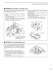
... CRYSTAL UNIT By installing the CR-338, the total frequency stability of the UT-102 to expose the adhesive strip. y Adjust the reference frequency at cables to their original positions. r Return the bottom cover to 64.00000 MHz with the CR-338. Frequency check point (Connect a frequency counter and adjust the...
... CRYSTAL UNIT By installing the CR-338, the total frequency stability of the UT-102 to expose the adhesive strip. y Adjust the reference frequency at cables to their original positions. r Return the bottom cover to 64.00000 MHz with the CR-338. Frequency check point (Connect a frequency counter and adjust the...
Instruction Manual
Page 52
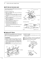
...;lter will not function properly. q Remove the bottom cover. w Slide the insulating case onto the UT-106 as shown in the diagram below . Connect the cable into J3 on the UT-106 and to its original position. y Turn the UT-106 unit over UT-106 P 1 (from J2602 on the UT-106... the UT-106 to their original positions. r Plug the connection cable (P1) from UT-106 is stored under the unit. r Mounting the filter with UT-106 s Optional IF filters Several IF filters are available for the IC-718. You can install 1 filter for your operating needs. (pgs, 24-25...
...;lter will not function properly. q Remove the bottom cover. w Slide the insulating case onto the UT-106 as shown in the diagram below . Connect the cable into J3 on the UT-106 and to its original position. y Turn the UT-106 unit over UT-106 P 1 (from J2602 on the UT-106... the UT-106 to their original positions. r Plug the connection cable (P1) from UT-106 is stored under the unit. r Mounting the filter with UT-106 s Optional IF filters Several IF filters are available for the IC-718. You can install 1 filter for your operating needs. (pgs, 24-25...
Instruction Manual
Page 53
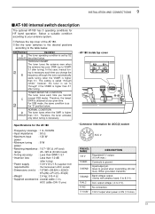
...) : 167(W) × 58.6(H) × 225(D) 69⁄16(W) × 25⁄17(H) × 87⁄8(D) • Weight : 2.4 kg; 5 lb 4 oz • Supplied accessories : coaxial cable (1 m), ACC cable (DIN 13 pins) • Connector information for HF band operation. When grounded, transmits. ➃ BAND Band voltage output. (Varies with amateur band; 0 to 8.0 V). ➄ ALC...
...) : 167(W) × 58.6(H) × 225(D) 69⁄16(W) × 25⁄17(H) × 87⁄8(D) • Weight : 2.4 kg; 5 lb 4 oz • Supplied accessories : coaxial cable (1 m), ACC cable (DIN 13 pins) • Connector information for HF band operation. When grounded, transmits. ➃ BAND Band voltage output. (Varies with amateur band; 0 to 8.0 V). ➄ ALC...
Instruction Manual
Page 54
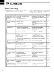
...center position. • Push [NB] to turn the function OFF. • Push [P.AMP] to locate the cause of this chart, contact your nearest Icom Dealer or Service Center. p. 2 p. 27 p. 3 p. 30 Programmed scan does • The same frequencies have not been • Program 2 or... of an external unit, if p. 6 desired. Memory scan does not • 2 or more memory channels. SOLUTION REF. • Reconnect the DC power cable correctly. • Check for 2 sec. p. 3 p. 3 RECEIVE TRANSMIT Receive audio is distorted. • The operating mode is not selected correctly. •...
...center position. • Push [NB] to turn the function OFF. • Push [P.AMP] to locate the cause of this chart, contact your nearest Icom Dealer or Service Center. p. 2 p. 27 p. 3 p. 30 Programmed scan does • The same frequencies have not been • Program 2 or... of an external unit, if p. 6 desired. Memory scan does not • 2 or more memory channels. SOLUTION REF. • Reconnect the DC power cable correctly. • Check for 2 sec. p. 3 p. 3 RECEIVE TRANSMIT Receive audio is distorted. • The operating mode is not selected correctly. •...
Instruction Manual
Page 55
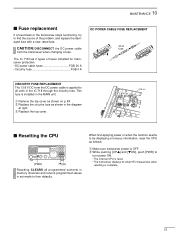
... CAUTION: DISCONNECT the DC power cable from the DC power cable is installed in the diagram at right. When first applying power or when the function seems to all programmed contents in memory channels and returns programmed values in the IC-718 through the circuitry fuse. PA ... fuses installed for transceiver protection. • DC power cable fuses FGB 20 A • Circuitry fuse FGB 4 A DC POWER CABLE FUSE REPLACEMENT 20 A fuse CIRCUITRY FUSE REPLACEMENT The 13.8 V DC from the transceiver when changing a fuse. The IC-718 has 2 types of the problem, and replace the...
... CAUTION: DISCONNECT the DC power cable from the DC power cable is installed in the diagram at right. When first applying power or when the function seems to all programmed contents in memory channels and returns programmed values in the IC-718 through the circuitry fuse. PA ... fuses installed for transceiver protection. • DC power cable fuses FGB 20 A • Circuitry fuse FGB 4 A DC POWER CABLE FUSE REPLACEMENT 20 A fuse CIRCUITRY FUSE REPLACEMENT The 13.8 V DC from the transceiver when changing a fuse. The IC-718 has 2 types of the problem, and replace the...
Instruction Manual
Page 57
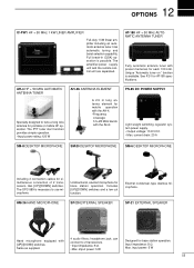
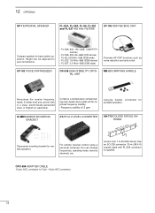
...portable or mobile HF operation. can connect to tune a long wire antenna for each 100 kHz. input power: 5 W 55 12 OPTIONS IC-PW1 HF + 50 MHz 1 KW LINER AMPLIFIER Full-duty 1 kW linear amplifier including an automatic antenna tuner. Full break-in (QSK)... OPC-589 is necessary to use microphone. current drain: 20 A SM-8 DESKTOP MICROPHONE SM-20 DESKTOP MICROPHONE SM-6 DESKTOP MICROPHONE Including 2 connection cables for AT-180 specifications. Unidirectional, electret microphone for base station operation. headphone jack; Includes [UP]/[DOWN] switches and a low cut function...
...portable or mobile HF operation. can connect to tune a long wire antenna for each 100 kHz. input power: 5 W 55 12 OPTIONS IC-PW1 HF + 50 MHz 1 KW LINER AMPLIFIER Full-duty 1 kW linear amplifier including an automatic antenna tuner. Full break-in (QSK)... OPC-589 is necessary to use microphone. current drain: 20 A SM-8 DESKTOP MICROPHONE SM-20 DESKTOP MICROPHONE SM-6 DESKTOP MICROPHONE Including 2 connection cables for AT-180 specifications. Unidirectional, electret microphone for base station operation. headphone jack; Includes [UP]/[DOWN] switches and a low cut function...
Instruction Manual
Page 58
...-96, FL-222 and FL-257 455 KHz FILTERS UT-106 DSP RECEIVE UNIT Compact speaker for portable operation. Covers from 1.9-30 MHz bands. IC-MB5 MOBILE MOUNTING BRACKET CT-17 CI-V LEVEL CONVERTER AH-710 FOLDED DIPOLE ANTENNA approx. 24.5 m; 80.3 ft Transceiver mounting bracket for your convenience.../-6dB (SSB wide) Provides AF DSP functions such as noise reduction and auto notch. Has an SO-239 connector. 30 m (98.4 ft) coaxial cable with PL-259 connector is supplied. UT-102 VOICE SYNTHESIZER CR-338 HIGH-STABILITY CRYSTAL UNIT MB-23 CARRYING HANDLE Announces the receive frequency, mode...
...-96, FL-222 and FL-257 455 KHz FILTERS UT-106 DSP RECEIVE UNIT Compact speaker for portable operation. Covers from 1.9-30 MHz bands. IC-MB5 MOBILE MOUNTING BRACKET CT-17 CI-V LEVEL CONVERTER AH-710 FOLDED DIPOLE ANTENNA approx. 24.5 m; 80.3 ft Transceiver mounting bracket for your convenience.../-6dB (SSB wide) Provides AF DSP functions such as noise reduction and auto notch. Has an SO-239 connector. 30 m (98.4 ft) coaxial cable with PL-259 connector is supplied. UT-102 VOICE SYNTHESIZER CR-338 HIGH-STABILITY CRYSTAL UNIT MB-23 CARRYING HANDLE Announces the receive frequency, mode...
Instruction Manual
Page 59
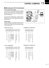
The Icom Communications Interface-V (CI-V) controls the following data formats. See p. 32 for setting the CI-V condition using the following functions of message code (fixed) 57 IC-718 ˛ ˛ BC-25 (optional) 9-15 V DC ct- 17 personal computer mini-plug cable CONTROLLER TO IC-718 q wert y u FE FE 5E E0 ... of message code (fixed) Preamble code (fixed) Controller's default address Transceiver's default address OK code (fixed) End of message code (fixed) IC-718 TO CONTROLLER q wert y u FE FE E0 5E Cn Sc Data area FD NG MESSAGE TO CONTROLLER FE FE E0 5E FA FD Preamble ...
The Icom Communications Interface-V (CI-V) controls the following data formats. See p. 32 for setting the CI-V condition using the following functions of message code (fixed) 57 IC-718 ˛ ˛ BC-25 (optional) 9-15 V DC ct- 17 personal computer mini-plug cable CONTROLLER TO IC-718 q wert y u FE FE 5E E0 ... of message code (fixed) Preamble code (fixed) Controller's default address Transceiver's default address OK code (fixed) End of message code (fixed) IC-718 TO CONTROLLER q wert y u FE FE E0 5E Cn Sc Data area FD NG MESSAGE TO CONTROLLER FE FE E0 5E FA FD Preamble ...


