

Instruction Manual
Page 3
... 51 s Opening the transceiver's case 48 s Optional bracket and carrying handle 48 s CR-338 HIGH STABILITY CRYSTAL UNIT .......... 49 s UT-102 VOICE SYNTHESIZER UNIT 49 s UT-106 DSP RECEIVE UNIT 50 s Optional IF filters 50 s AT-180 internal switch description 51 10 MAINTENANCE 52 - 53 s ... Dial lock function 19 5 RECEIVE AND TRANSMIT 20 - 34 s Mode selection 20 s Squelch and RF gain 20 s Function for receive 21 s DSP function (option 23 s Filter selection 24 s Filter setting 25 s Function for transmit 26 s Split frequency operation 30 s SWR 30 s Function for ...
... 51 s Opening the transceiver's case 48 s Optional bracket and carrying handle 48 s CR-338 HIGH STABILITY CRYSTAL UNIT .......... 49 s UT-102 VOICE SYNTHESIZER UNIT 49 s UT-106 DSP RECEIVE UNIT 50 s Optional IF filters 50 s AT-180 internal switch description 51 10 MAINTENANCE 52 - 53 s ... Dial lock function 19 5 RECEIVE AND TRANSMIT 20 - 34 s Mode selection 20 s Squelch and RF gain 20 s Function for receive 21 s DSP function (option 23 s Filter selection 24 s Filter setting 25 s Function for transmit 26 s Split frequency operation 30 s SWR 30 s Function for ...
Instruction Manual
Page 6
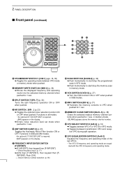
... SWITCH/9 [VOX•9] (p. 27) ➥ Turn the VOX function ON or OFF when pushed in SSB and AM modes. • An optional UT-106 DSP UNIT is required. • [NR] appears on the display. @7 FRQUENCY INPUT/ENTER SWITCH [F-INP/ENT] ➥ [F-INP/ENT], then keypad then [F-INP/ENT]...VFO/MEMORY SWITCH/1 [V/M•1] (pgs. 16, 35) ➥ Toggles the operating mode between VFO A or VFO B in all modes. • An optional UT-106 DSP UNIT is required. • [ANF] appears on the display. ➥ Enters noise reduction level set mode when pushed for 1 sec. @6 ANF SWITCH/0 [ANF•0] ...
... SWITCH/9 [VOX•9] (p. 27) ➥ Turn the VOX function ON or OFF when pushed in SSB and AM modes. • An optional UT-106 DSP UNIT is required. • [NR] appears on the display. @7 FRQUENCY INPUT/ENTER SWITCH [F-INP/ENT] ➥ [F-INP/ENT], then keypad then [F-INP/ENT]...VFO/MEMORY SWITCH/1 [V/M•1] (pgs. 16, 35) ➥ Toggles the operating mode between VFO A or VFO B in all modes. • An optional UT-106 DSP UNIT is required. • [ANF] appears on the display. ➥ Enters noise reduction level set mode when pushed for 1 sec. @6 ANF SWITCH/0 [ANF•0] ...
Instruction Manual
Page 7
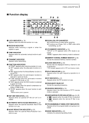
w RECEIVE INDICATOR Appears while receiving a signal or when the squelch is installed. y DSP UNIT INDICATOR (p. 49) Appears when an optional UT-106 DSP UNIT is open. 2 PANEL DESCRIPTION s Function display !9 q w e r t y u i o q LOCK INDICATOR (p. 19) Appears when the dial lock function is in SSB mode. ➥ "SCAN" appears when the scan ...
w RECEIVE INDICATOR Appears while receiving a signal or when the squelch is installed. y DSP UNIT INDICATOR (p. 49) Appears when an optional UT-106 DSP UNIT is open. 2 PANEL DESCRIPTION s Function display !9 q w e r t y u i o q LOCK INDICATOR (p. 19) Appears when the dial lock function is in SSB mode. ➥ "SCAN" appears when the scan ...
Instruction Manual
Page 25
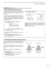
... [NR] again to turn the auto notch function ON. • [ANF] indicator appears. 5 RECEIVE AND TRANSMIT s DSP function (Requires an optional UT-106 DSP UNIT) ï NR (Noise reduction) function When an optional UT-106 is installed (DSP appears in SSB mode only. to turn the noise reduction OFF. • [NR] indicator disappears. ï...
... [NR] again to turn the auto notch function ON. • [ANF] indicator appears. 5 RECEIVE AND TRANSMIT s DSP function (Requires an optional UT-106 DSP UNIT) ï NR (Noise reduction) function When an optional UT-106 is installed (DSP appears in SSB mode only. to turn the noise reduction OFF. • [NR] indicator disappears. ï...
Instruction Manual
Page 52
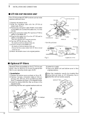
i Return the bottom cover to their original positions. y Return the MAIN unit and bottom cover to its original position. q Remove the bottom cover. You can install 1 filter for the IC-718. w Remove 7 screws, connection cable p1 from J1, p5 from J701, W4 from J4101 and...the installed filter will not function properly. 9 INSTALLATION AND CONNECTIONS s UT-106 DSP RECEIVE UNIT The UT-106 provides AF DSP functions such as shown on the p. 48. flat cable P 2601 Turn the unit over J 2602 MAIN unit Fig. 1 UT-106 J 2602 Fig. 2 insulating case " Flat cable* Surplus ...
i Return the bottom cover to their original positions. y Return the MAIN unit and bottom cover to its original position. q Remove the bottom cover. You can install 1 filter for the IC-718. w Remove 7 screws, connection cable p1 from J1, p5 from J701, W4 from J4101 and...the installed filter will not function properly. 9 INSTALLATION AND CONNECTIONS s UT-106 DSP RECEIVE UNIT The UT-106 provides AF DSP functions such as shown on the p. 48. flat cable P 2601 Turn the unit over J 2602 MAIN unit Fig. 1 UT-106 J 2602 Fig. 2 insulating case " Flat cable* Surplus ...
Instruction Manual
Page 58
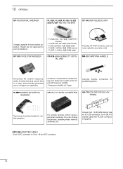
...IC-MB5 MOBILE MOUNTING BRACKET CT-17 CI-V LEVEL CONVERTER AH-710 FOLDED DIPOLE ANTENNA approx. 24.5 m; 80.3 ft Transceiver mounting bracket for portable operation. For remote receiver control using a personal computer. You can be adjusted for base station operation. UT-102 VOICE SYNTHESIZER CR-338 HIGH-STABILITY CRYSTAL UNIT...memory channels, etc. 12 OPTIONS SP-7 EXTERNAL SPEAKER FL-52A, FL-53A, FL-96, FL-222 and FL-257 455 KHz FILTERS UT-106 DSP RECEIVE UNIT Compact speaker for your convenience. • FL-52A: 500 Hz/-6dB (CW/RTTY narrow) • FL-53A: 250 Hz/-6dB (CW ...
...IC-MB5 MOBILE MOUNTING BRACKET CT-17 CI-V LEVEL CONVERTER AH-710 FOLDED DIPOLE ANTENNA approx. 24.5 m; 80.3 ft Transceiver mounting bracket for portable operation. For remote receiver control using a personal computer. You can be adjusted for base station operation. UT-102 VOICE SYNTHESIZER CR-338 HIGH-STABILITY CRYSTAL UNIT...memory channels, etc. 12 OPTIONS SP-7 EXTERNAL SPEAKER FL-52A, FL-53A, FL-96, FL-222 and FL-257 455 KHz FILTERS UT-106 DSP RECEIVE UNIT Compact speaker for your convenience. • FL-52A: 500 Hz/-6dB (CW/RTTY narrow) • FL-53A: 250 Hz/-6dB (CW ...


