
Installation Guide
Page 65
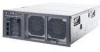
The following illustration shows the LEDs on server components: Remove the top cover to the left; Light Path Diagnostics REMIND OVER SPEC PS1 PS2 CPU CNFG MEM NMI S ERR SP DASD RAID FAN TEMP BRD PCI 3. LEDs on the I/O board. The following illustration shows the ...error will light the LED on LED Power-control button Release latch USB connectors 2. Chapter 6. Locator LED Information LED Hard disk drive activity LED System-error LED Power-on top of the operator information drawer to look inside the server for lit LEDs. then, slide it indicates that there is...
The following illustration shows the LEDs on server components: Remove the top cover to the left; Light Path Diagnostics REMIND OVER SPEC PS1 PS2 CPU CNFG MEM NMI S ERR SP DASD RAID FAN TEMP BRD PCI 3. LEDs on the I/O board. The following illustration shows the ...error will light the LED on LED Power-control button Release latch USB connectors 2. Chapter 6. Locator LED Information LED Hard disk drive activity LED System-error LED Power-on top of the operator information drawer to look inside the server for lit LEDs. then, slide it indicates that there is...