User Manual
Page 7
... a hot-swap power supply 24 Installing or replacing an adapter 25 Installing or replacing a hot-plug adapter (slot 6 28 Installing an IBM Remote Supervisor Adapter II SlimLine 29 Installing the ServeRAID-7k adapter 31 Installing a hot-swap hard disk drive 32 Installing memory modules 33 Installing a microprocessor 35 Replacing a microprocessor and heat sink 39 Replacing the battery 42 Completing the installation 45 Installing the server bezel and left-side cover 46 Installing the server door 48 Connecting the cables 49 Updating the server configuration 50 Input/output connectors...
... a hot-swap power supply 24 Installing or replacing an adapter 25 Installing or replacing a hot-plug adapter (slot 6 28 Installing an IBM Remote Supervisor Adapter II SlimLine 29 Installing the ServeRAID-7k adapter 31 Installing a hot-swap hard disk drive 32 Installing memory modules 33 Installing a microprocessor 35 Replacing a microprocessor and heat sink 39 Replacing the battery 42 Completing the installation 45 Installing the server bezel and left-side cover 46 Installing the server door 48 Connecting the cables 49 Updating the server configuration 50 Input/output connectors...
User Manual
Page 8
...Manual and Troubleshooting Guide Service replaceable units 55 Microprocessor removal 56 Thermal grease 58 Operator information panel (external LED card 59 Diagnostics panel card 61 Power reset card 62 Diskette drive 63 CD-ROM drive 64 Hard disk drive backplane 65 Power supply cage assembly 66 Center-fan and adapter-support bracket 67 Center-fan support bracket (dual fan guide 69 Adapter-support bracket 70 Front fan housing (PCI fan guide 72 Front USB connector assembly 73 Switch card assembly 74 System board 76 System-board internal connectors 78 System-board internal cable...
...Manual and Troubleshooting Guide Service replaceable units 55 Microprocessor removal 56 Thermal grease 58 Operator information panel (external LED card 59 Diagnostics panel card 61 Power reset card 62 Diskette drive 63 CD-ROM drive 64 Hard disk drive backplane 65 Power supply cage assembly 66 Center-fan and adapter-support bracket 67 Center-fan support bracket (dual fan guide 69 Adapter-support bracket 70 Front fan housing (PCI fan guide 72 Front USB connector assembly 73 Switch card assembly 74 System board 76 System-board internal connectors 78 System-board internal cable...

User Manual
Page 9
... Serial port error symptoms 130 ServerGuide error symptoms 131 Software error symptoms 132 Service processor error codes 132 SCSI error codes 132 ServeRAID error codes 133 POST (ISPR) error procedures 134 Temperature error messages 136 Fan error messages 136 Power error messages 137 System shutdown 137 Voltage related system shutdown 137 Temperature related system shutdown 138 DASD checkout 138 Host built-in self test (BIST 139 Bus fault messages 139 Undetermined problems 140 Problem determination tips 141 Chapter 7. Parts listing Type 8841 143 System 143 System replaceable...
... Serial port error symptoms 130 ServerGuide error symptoms 131 Software error symptoms 132 Service processor error codes 132 SCSI error codes 132 ServeRAID error codes 133 POST (ISPR) error procedures 134 Temperature error messages 136 Fan error messages 136 Power error messages 137 System shutdown 137 Voltage related system shutdown 137 Temperature related system shutdown 138 DASD checkout 138 Host built-in self test (BIST 139 Bus fault messages 139 Undetermined problems 140 Problem determination tips 141 Chapter 7. Parts listing Type 8841 143 System 143 System replaceable...

User Manual
Page 13
... Serial Bus (USB) v1.1 or v2.0 connectors (one bay) v One 3.5-inch removable-media drive bay (diskette drive installed) PCI expansion slots: v One Active PCI-X™ (hot-plug) 133 MHz/64-bit v Two PCI-X non-hot-plug 100 MHz/64-bit v Two PCI Express x4 non-hot-plug v One PCI non-hot-plug 33 MHz/32-bit Upgradeable microcode: BIOS, diagnostics, and IBM integrated system management upgrades (when available) can update EEPROMs on the system board Predictive Failure Analysis® (PFA) alerts: v Power supplies v Fans v Memory v Hard disk drives...
... Serial Bus (USB) v1.1 or v2.0 connectors (one bay) v One 3.5-inch removable-media drive bay (diskette drive installed) PCI expansion slots: v One Active PCI-X™ (hot-plug) 133 MHz/64-bit v Two PCI-X non-hot-plug 100 MHz/64-bit v Two PCI Express x4 non-hot-plug v One PCI non-hot-plug 33 MHz/32-bit Upgradeable microcode: BIOS, diagnostics, and IBM integrated system management upgrades (when available) can update EEPROMs on the system board Predictive Failure Analysis® (PFA) alerts: v Power supplies v Fans v Memory v Hard disk drives...

User Manual
Page 15
... power source. v System-error LED: When this amber LED is activity on a hard disk drive. v System locator LED: Use this LED to light this LED remotely. USB 3 connector: Connect a USB device to further isolate the error. Hard disk drive activity LED: When this LED is flashing, it indicates that the associated hard disk drive is in use. You can use . v Hard disk drive activity LED: When this green LED is flashing rapidly it indicates that there is lit it indicates that a system error has occurred. Use the diagnostic LED panel and the system service...
... power source. v System-error LED: When this amber LED is activity on a hard disk drive. v System locator LED: Use this LED to light this LED remotely. USB 3 connector: Connect a USB device to further isolate the error. Hard disk drive activity LED: When this LED is flashing, it indicates that the associated hard disk drive is in use. You can use . v Hard disk drive activity LED: When this green LED is flashing rapidly it indicates that there is lit it indicates that a system error has occurred. Use the diagnostic LED panel and the system service...

User Manual
Page 17
... Management interconnect network that is connected to an optional Remote Supervisor Adapter II SlimLine installed in any other combination of LEDs, see "Light path diagnostics" on the server. The server can turn on the Ethernet connector. v If the server is connected to ac power but is connected to turn on in another server. v If your operating system supports the systems-management software for the service processor is being transmitted or received between the server and the network device...
... Management interconnect network that is connected to an optional Remote Supervisor Adapter II SlimLine installed in any other combination of LEDs, see "Light path diagnostics" on the server. The server can turn on the Ethernet connector. v If the server is connected to ac power but is connected to turn on in another server. v If your operating system supports the systems-management software for the service processor is being transmitted or received between the server and the network device...
User Manual
Page 36
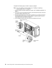
...install the adapter.) 4. Complete the following steps to "Installing or replacing a hot-plug adapter (slot 6)" on page 11. 2. Adapterretention latch Backup expansion-slot screws Expansionslot cover Adapter Adapterretention clip Adapter-support bracket 26 xSeries 236 Type 8841: Hardware Maintenance Manual and Troubleshooting Guide Remove the cover. 3. Read the safety information beginning on page v and "Installation guidelines" on page 28. 1. Lift the adapter-retention latch and remove the expansion-slot cover. Turn off the server and peripheral devices, and disconnect the power...
...install the adapter.) 4. Complete the following steps to "Installing or replacing a hot-plug adapter (slot 6)" on page 11. 2. Adapterretention latch Backup expansion-slot screws Expansionslot cover Adapter Adapterretention clip Adapter-support bracket 26 xSeries 236 Type 8841: Hardware Maintenance Manual and Troubleshooting Guide Remove the cover. 3. Read the safety information beginning on page v and "Installation guidelines" on page 28. 1. Lift the adapter-retention latch and remove the expansion-slot cover. Turn off the server and peripheral devices, and disconnect the power...

User Manual
Page 104
...; The error LEDs on the light path diagnostics panel refers to view lit LEDs inside the server with step 5. 5. Go to the failing microprocessor. see "System-board LEDs" on or near the individual component. then, remove the cover and look on the system board for any lit error LEDs. This label gives an overview of the server. 1 POWER SUPPLY 2 CONFIG TEMP REMIND MEMORY DASD/ RAID FAN CPU S_ERR VRM PCI BUS SERVICE NMI PROCESSOR BUS 3. v Some error conditions are located on page...
...; The error LEDs on the light path diagnostics panel refers to view lit LEDs inside the server with step 5. 5. Go to the failing microprocessor. see "System-board LEDs" on or near the individual component. then, remove the cover and look on the system board for any lit error LEDs. This label gives an overview of the server. 1 POWER SUPPLY 2 CONFIG TEMP REMIND MEMORY DASD/ RAID FAN CPU S_ERR VRM PCI BUS SERVICE NMI PROCESSOR BUS 3. v Some error conditions are located on page...
User Manual
Page 107
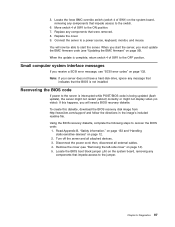
... display video (no video). Note: If your server does not have a hard disk drive, ignore any components that were removed. 8. Turn off the server and all external cables. 4. When the update is complete, return switch 4 of SW1 to the OFF position. To create this happens, you will now be able to recover the BIOS code: 1. Using the BIOS recovery diskette, complete the following steps to start the server, you receive a SCSI error message...
... display video (no video). Note: If your server does not have a hard disk drive, ignore any components that were removed. 8. Turn off the server and all external cables. 4. When the update is complete, return switch 4 of SW1 to the OFF position. To create this happens, you will now be able to recover the BIOS code: 1. Using the BIOS recovery diskette, complete the following steps to start the server, you receive a SCSI error message...
User Manual
Page 110
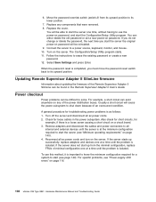
..., monitor, and mouse. 10. When the password reset is a loose screw causing a short circuit on a circuit board. 3. Usually a short circuit will be able to start the server (see "Power-supply LED errors" on password will cause the power subsystem to use this method, it is as follows: 1. Check for loose cables in the Remote Supervisor Adapter II User's Guide. Reconnect all ac power cords and turn on password. For specific problems, see "Minimum operating requirements" on password...
..., monitor, and mouse. 10. When the password reset is a loose screw causing a short circuit on a circuit board. 3. Usually a short circuit will be able to start the server (see "Power-supply LED errors" on password will cause the power subsystem to use this method, it is as follows: 1. Check for loose cables in the Remote Supervisor Adapter II User's Guide. Reconnect all ac power cords and turn on password. For specific problems, see "Minimum operating requirements" on password...
User Manual
Page 113
... 6. Configuration problems can cause false errors and symptoms. 2. For IBM devices not supported by this symptom-to-FRU index to have available when servicing the server. © Copyright IBM Corp. 2004, 2007 103 The symptom-to -FRU index Beep symptoms 104 No-beep symptoms 108 POST error codes 108 Light path diagnostic errors 114 Power-supply LED errors 116 Diagnostic error codes 116 Error symptoms 122 CD-ROM drive error symptoms 123 Diskette drive error symptoms 123 General error symptoms 124 Hard disk drive error...
... 6. Configuration problems can cause false errors and symptoms. 2. For IBM devices not supported by this symptom-to-FRU index to have available when servicing the server. © Copyright IBM Corp. 2004, 2007 103 The symptom-to -FRU index Beep symptoms 104 No-beep symptoms 108 POST error codes 108 Light path diagnostic errors 114 Power-supply LED errors 116 Diagnostic error codes 116 Error symptoms 122 CD-ROM drive error symptoms 123 Diskette drive error symptoms 123 General error symptoms 124 Hard disk drive error...

User Manual
Page 116
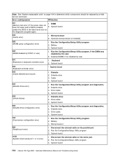
.... 3. Run the Configuration/Setup Utility program. 106 xSeries 236 Type 8841: Hardware Maintenance Manual and Troubleshooting Guide Microprocessor 2. Disconnect the server power cord from Disabled to determine which components should be replaced by a blank display screen. DASD backplane. 5. Install or reseat the memory modules, and then do a 3 boot reset. Run Diagnostics. 2. System board 3-2-4 (Failure comparing CMOS memory size against actual) 1. DIMMs. 4. Power supply. 6. Power cage assembly, if installed. 7. 12C Cable. 3-3-3 1. (No operational memory in slot...
.... 3. Run the Configuration/Setup Utility program. 106 xSeries 236 Type 8841: Hardware Maintenance Manual and Troubleshooting Guide Microprocessor 2. Disconnect the server power cord from Disabled to determine which components should be replaced by a blank display screen. DASD backplane. 5. Install or reseat the memory modules, and then do a 3 boot reset. Run Diagnostics. 2. System board 3-2-4 (Failure comparing CMOS memory size against actual) 1. DIMMs. 4. Power supply. 6. Power cage assembly, if installed. 7. 12C Cable. 3-3-3 1. (No operational memory in slot...
User Manual
Page 120
...installed) 262 (DRAM parity configuration error) 1. System board. 289 (DIMM disabled by the user. 2. Disabled DIMM, if not disabled by a field service technician. Keyboard 2. System board. 605 (Unlock failure) 1. Drive cable 3. Microprocessor. 962 (Parallel port error) 1. Disconnect the external cable on the parallel port. 2. Note: See "System replaceable units" on page 144 to the latest level and run the diagnostic program again. Battery. 3. Diskette drive. 3. Diskette drive. 3. System board. 110 xSeries 236 Type 8841: Hardware Maintenance Manual and Troubleshooting...
...installed) 262 (DRAM parity configuration error) 1. System board. 289 (DIMM disabled by the user. 2. Disabled DIMM, if not disabled by a field service technician. Keyboard 2. System board. 605 (Unlock failure) 1. Drive cable 3. Microprocessor. 962 (Parallel port error) 1. Disconnect the external cable on the parallel port. 2. Note: See "System replaceable units" on page 144 to the latest level and run the diagnostic program again. Battery. 3. Diskette drive. 3. Diskette drive. 3. System board. 110 xSeries 236 Type 8841: Hardware Maintenance Manual and Troubleshooting...
User Manual
Page 133
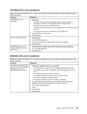
... the manual tray-release opening. 2. v The software program is not working properly. 1. System board. Symptom-to determine which components should be powered on.) 1. CD-ROM drive. Run CD-ROM diagnostics. 3. CD-ROM drive. CD-ROM drive. Chapter 6. v The signal cable and connector are not damaged and the connector pins are installed correctly. CD is working . (The server must be replaced by a field service technician. Check the connector and signal cable for the CD-ROM drive. 2. Run CD-ROM diagnostics...
... the manual tray-release opening. 2. v The software program is not working properly. 1. System board. Symptom-to determine which components should be powered on.) 1. CD-ROM drive. Run CD-ROM diagnostics. 3. CD-ROM drive. CD-ROM drive. Chapter 6. v The signal cable and connector are not damaged and the connector pins are installed correctly. CD is working . (The server must be replaced by a field service technician. Check the connector and signal cable for the CD-ROM drive. 2. Run CD-ROM diagnostics...
User Manual
Page 135
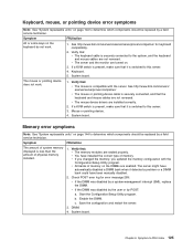
System board. v You have installed the correct type of physical memory installed. 1. Check POST error log for keyboard compatibility. 2. b. See http://www.ibm.com/servers/ eserver/serverproven/compat/us / for error message 289: v If the DIMM was disabled by the user or by POST: a. v All banks of memory on the DIMMs are turned on. 3. Start the Configuration/Setup Utility program. c. Verify that : v The mouse is compatible with the Configuration/Setup Utility program. The mouse or pointing device does not...
System board. v You have installed the correct type of physical memory installed. 1. Check POST error log for keyboard compatibility. 2. b. See http://www.ibm.com/servers/ eserver/serverproven/compat/us / for error message 289: v If the DIMM was disabled by the user or by POST: a. v All banks of memory on the DIMMs are turned on. 3. Start the Configuration/Setup Utility program. c. Verify that : v The mouse is compatible with the Configuration/Setup Utility program. The mouse or pointing device does not...
User Manual
Page 136
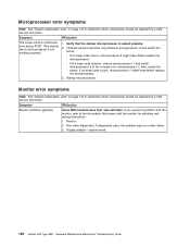
.../action Monitor problems (general). Run video diagnostics. If you suspect a problem with the monitor, refer to the information that the startup microprocessor is not working properly.) 1. Verify that comes with the monitor for microprocessor 1; Microprocessor error symptoms Note: See "System replaceable units" on page 144 to determine which components should be replaced by a field service technician. Display adapter / system board. 126 xSeries 236 Type 8841: Hardware Maintenance Manual and Troubleshooting Guide...
.../action Monitor problems (general). Run video diagnostics. If you suspect a problem with the monitor, refer to the information that the startup microprocessor is not working properly.) 1. Verify that comes with the monitor for microprocessor 1; Microprocessor error symptoms Note: See "System replaceable units" on page 144 to determine which components should be replaced by a field service technician. Display adapter / system board. 126 xSeries 236 Type 8841: Hardware Maintenance Manual and Troubleshooting Guide...
User Manual
Page 138
.... If this happens, turn off the monitor. (Moving a color monitor while it is available for the server (see the ServerProven® list at http://www.ibm.com/pc/compat/). v The option is changed, you just installed. 128 xSeries 236 Type 8841: Hardware Maintenance Manual and Troubleshooting Guide Whenever memory or an option is installed correctly. b. Notes: a. Video adapter, if installed. 3. Option you must update the configuration. 2. An enhanced monitor cable with the option...
.... If this happens, turn off the monitor. (Moving a color monitor while it is available for the server (see the ServerProven® list at http://www.ibm.com/pc/compat/). v The option is changed, you just installed. 128 xSeries 236 Type 8841: Hardware Maintenance Manual and Troubleshooting Guide Whenever memory or an option is installed correctly. b. Notes: a. Video adapter, if installed. 3. Option you must update the configuration. 2. An enhanced monitor cable with the option...
User Manual
Page 140
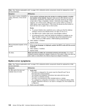
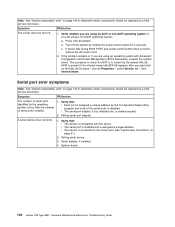
... Version tab → click Internal Name. If you are using a non-ACPI operating system: a. If server fails during BIOS POST and power-control button does not work . 1. Failing serial device. 3. Serial adapter, if installed. 4. Verify that : v Each port is assigned a unique address by the operating system is seated properly. 2. System board. 130 xSeries 236 Type 8841: Hardware Maintenance Manual and Troubleshooting Guide ACPI is connected to the correct port (see "Input/output connectors" on page 51). 2. Verify that : v The device is disabled...
... Version tab → click Internal Name. If you are using a non-ACPI operating system: a. If server fails during BIOS POST and power-control button does not work . 1. Failing serial device. 3. Serial adapter, if installed. 4. Verify that : v Each port is assigned a unique address by the operating system is seated properly. 2. System board. 130 xSeries 236 Type 8841: Hardware Maintenance Manual and Troubleshooting Guide ACPI is connected to the correct port (see "Input/output connectors" on page 51). 2. Verify that : v The device is disabled...
User Manual
Page 142
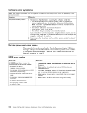
... to operate on the server. If you received any error messages when using works on the server. 2. Service processor error codes When viewed in the same SCSI chain v A missing or improperly installed SCSI terminator v A defective SCSI terminator v An improperly installed cable v A defective cable FRU/action 1. Make sure that comes with the software. If you are configured correctly. 132 xSeries 236 Type 8841: Hardware Maintenance Manual and Troubleshooting Guide v Other software works on the server. External SCSI devices must be turned on...
... to operate on the server. If you received any error messages when using works on the server. 2. Service processor error codes When viewed in the same SCSI chain v A missing or improperly installed SCSI terminator v A defective SCSI terminator v An improperly installed cable v A defective cable FRU/action 1. Make sure that comes with the software. If you are configured correctly. 132 xSeries 236 Type 8841: Hardware Maintenance Manual and Troubleshooting Guide v Other software works on the server. External SCSI devices must be turned on...

User Manual
Page 205
... 99 power-on jumper 99 PCI bus A 25 bus B 25 bus C 25 fan guide, removing 72 PCI expansion slots 3 pointing-device (auxiliary-device) connector 52 port connectors 82 Universal Serial Bus 54 POST about 90 beep codes, error messages 89 completion LED 5 error codes 108 error logs 89 power checkout 100 control button 5 cord connector 7 cords 148 error messages 137 LED 5 LEDs 116 problems 129 power on password override switch 81 problem determination tips 141 problem solving 87 problems BIST 139 bus fault 139 CD-ROM drive 123 DASD checkout 138 diskette drive 123 general 124 hard disk drives 124...
... 99 power-on jumper 99 PCI bus A 25 bus B 25 bus C 25 fan guide, removing 72 PCI expansion slots 3 pointing-device (auxiliary-device) connector 52 port connectors 82 Universal Serial Bus 54 POST about 90 beep codes, error messages 89 completion LED 5 error codes 108 error logs 89 power checkout 100 control button 5 cord connector 7 cords 148 error messages 137 LED 5 LEDs 116 problems 129 power on password override switch 81 problem determination tips 141 problem solving 87 problems BIST 139 bus fault 139 CD-ROM drive 123 DASD checkout 138 diskette drive 123 general 124 hard disk drives 124...


