Service Guide
Page 4
... 64 System Service Clearances 65 Power Cables 66 Service Inspection Guide 67 Chapter 2. Riser Card Memory Placement Rules 26 I/O Drawer Features 27 I/O Drawer Addressing 27 I/O Drawer and Power Supply LED Status 28 Message Hierarchy for the pSeries and RS/6000 71 Eserver Using the Service Processor and Electronic Service Agent Features 72 Service Processor 72 Electronic Service Agent 73...
... 64 System Service Clearances 65 Power Cables 66 Service Inspection Guide 67 Chapter 2. Riser Card Memory Placement Rules 26 I/O Drawer Features 27 I/O Drawer Addressing 27 I/O Drawer and Power Supply LED Status 28 Message Hierarchy for the pSeries and RS/6000 71 Eserver Using the Service Processor and Electronic Service Agent Features 72 Service Processor 72 Electronic Service Agent 73...

Service Guide
Page 6
... 417 Remote Initial Program Load Setup 417 SCSI Utilities 421 Select Console 421 MultiBoot 422 Select Language 425 OK Prompt 425 Exiting System Management Services 425 vi Service Guide Call-In/Call-Out Setup Menu 391 Modem Configuration Menu 392 Serial Port Selection Menu 393 Serial Port Speed Setup Menu 393 Telephone Number...
... 417 Remote Initial Program Load Setup 417 SCSI Utilities 421 Select Console 421 MultiBoot 422 Select Language 425 OK Prompt 425 Exiting System Management Services 425 vi Service Guide Call-In/Call-Out Setup Menu 391 Modem Configuration Menu 392 Serial Port Selection Menu 393 Serial Port Speed Setup Menu 393 Telephone Number...

Service Guide
Page 8
... and Test 497 Service Processor Setup Checklist 497 Testing the Setup 498 Testing Call-In 498 Testing Call-Out 498 Serial Port Configuration 499 Appendix D. Fan Controller Card 461 ... Battery 469 Removal 469 Replacement 470 Chapter 10. Notices 495 Appendix C. Modem Configurations 501 Sample Modem Configuration Files 501 Generic Modem Configuration Files 501 viii Service Guide Environmental Notices 493 Product Recycling and Disposal 493 Environmental Design 493 Acoustical Noise Emissions 493 Declared Acoustical Noise Emissions 494 Noise Emission Notes 494 Appendix...
... and Test 497 Service Processor Setup Checklist 497 Testing the Setup 498 Testing Call-In 498 Testing Call-Out 498 Serial Port Configuration 499 Appendix D. Fan Controller Card 461 ... Battery 469 Removal 469 Replacement 470 Chapter 10. Notices 495 Appendix C. Modem Configurations 501 Sample Modem Configuration Files 501 Generic Modem Configuration Files 501 viii Service Guide Environmental Notices 493 Product Recycling and Disposal 493 Environmental Design 493 Acoustical Noise Emissions 493 Declared Acoustical Noise Emissions 494 Noise Emission Notes 494 Appendix...

Service Guide
Page 12
... risk of the customer to ensure that the outlet is the responsibility of electrical shock, disconnect two power supply cords before servicing. xii Service Guide It is correctly wired and grounded to prevent an electrical shock. Use one power supply cord. Use this power cable with...for display stations, printers, telephones, or station protectors for those devices are to the system. Power supplies are not serviceable and are unplugged before you are connecting or disconnecting devices attached to prevent a possible shock from touching two surfaces with different electrical...
... risk of the customer to ensure that the outlet is the responsibility of electrical shock, disconnect two power supply cords before servicing. xii Service Guide It is correctly wired and grounded to prevent an electrical shock. Use one power supply cord. Use this power cable with...for display stations, printers, telephones, or station protectors for those devices are to the system. Power supplies are not serviceable and are unplugged before you are connecting or disconnecting devices attached to prevent a possible shock from touching two surfaces with different electrical...

Service Guide
Page 17
... be installed. v The RS/6000 Enterprise Server Model H80 pSeries 660 Models 6H0 and Eserver 6H1 User's Guide, order number SA38-0565, contains information on how to use the system, use diagnostics, use service aids, and verify system operations. To access the online books, visit our Web site at: http://www.rs6000.ibm.com/resource/hardware_docs...
... be installed. v The RS/6000 Enterprise Server Model H80 pSeries 660 Models 6H0 and Eserver 6H1 User's Guide, order number SA38-0565, contains information on how to use the system, use diagnostics, use service aids, and verify system operations. To access the online books, visit our Web site at: http://www.rs6000.ibm.com/resource/hardware_docs...

Service Guide
Page 18
xviii Service Guide This manual is intended to help you plan your installation. v The Site and Hardware Planning Information, order number SA38-0508, contains information to supplement information found in this system. v The RS/6000 and pSeries Adapters, Devices, and Cable Information for adapters that can be trademarks or service marks of International Business Machines Corporation...
xviii Service Guide This manual is intended to help you plan your installation. v The Site and Hardware Planning Information, order number SA38-0508, contains information to supplement information found in this system. v The RS/6000 and pSeries Adapters, Devices, and Cable Information for adapters that can be trademarks or service marks of International Business Machines Corporation...

Service Guide
Page 20
...use 200 - 240 V ac power or -48 V dc power. or 64-bit PCI adapters. Memory v 256 MB (minimum) to access the service processor menus. Power is connected from older RS/6000 systems can only be used when upgrading the system memory. The PCI bus speeds are available. each drawer independently....Six-Way Processor" on page 3 and "Data Flow with One-Way Processor" on page 4. 2 Service Guide v Certain 32 MB DIMMs from the distribution bus to each riser card has sixteen sockets. 128 MB, 256 MB, 512 MB, and 1 GB dual inline memory modules (DIMMs) are as follows: v Up to 33 Mhz ...
...use 200 - 240 V ac power or -48 V dc power. or 64-bit PCI adapters. Memory v 256 MB (minimum) to access the service processor menus. Power is connected from older RS/6000 systems can only be used when upgrading the system memory. The PCI bus speeds are available. each drawer independently....Six-Way Processor" on page 3 and "Data Flow with One-Way Processor" on page 4. 2 Service Guide v Certain 32 MB DIMMs from the distribution bus to each riser card has sixteen sockets. 128 MB, 256 MB, 512 MB, and 1 GB dual inline memory modules (DIMMs) are as follows: v Up to 33 Mhz ...

Service Guide
Page 22
... P P L2 Bus 0 Controller 6XX L2 P Bus 1 P L2 P L2 Memory Cards (1 or 2) SMI BUS 0, 1 SMI BUS 2, 3 SMI SMI RIO SMI SMI (2) OR 4-Way System P L2 P L2 256 MB - 32 GB 32-bit PCI Bus 0 10/100 E'net SCSI Converged Support Processor PCI Host Bridge 64-bit PCI Bus 1 64-bit PCI Bus 2 PCI... be powered on after the following cables are connected: v V/S COMM Cable v All RIO cables v All SPCN cables v JTAG Cable v All PCI cables to supported drawers 4 Service Guide
... P P L2 Bus 0 Controller 6XX L2 P Bus 1 P L2 P L2 Memory Cards (1 or 2) SMI BUS 0, 1 SMI BUS 2, 3 SMI SMI RIO SMI SMI (2) OR 4-Way System P L2 P L2 256 MB - 32 GB 32-bit PCI Bus 0 10/100 E'net SCSI Converged Support Processor PCI Host Bridge 64-bit PCI Bus 1 64-bit PCI Bus 2 PCI... be powered on after the following cables are connected: v V/S COMM Cable v All RIO cables v All SPCN cables v JTAG Cable v All PCI cables to supported drawers 4 Service Guide

Service Guide
Page 24
...POST indicator displays, you must use the numeric number keys to initiate a service mode boot is now open. See "POST Keys" for pressing a key to access the System Management Services, or to enter input. 6 Service Guide Each word is an indicator of the tests that the system starts a ... if pressed after the keyboard POST indicator displays and before the last POST indicator speaker displays, cause the system to start services or to initiate service mode boots used for configuring the system and diagnosing problems. The keys are described below: Note: The program function keys (...
...POST indicator displays, you must use the numeric number keys to initiate a service mode boot is now open. See "POST Keys" for pressing a key to access the System Management Services, or to enter input. 6 Service Guide Each word is an indicator of the tests that the system starts a ... if pressed after the keyboard POST indicator displays and before the last POST indicator speaker displays, cause the system to start services or to initiate service mode boots used for configuring the system and diagnosing problems. The keys are described below: Note: The program function keys (...

Service Guide
Page 26
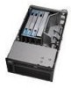
R Primary I /O drawer. System Unit Locations The system consists of a minimum of the system is required. An additional I/O drawer can be added if further expansion of two drawers in one rack: the CEC drawer and the primary I /O Drawer (5 EIA Units) CEC Drawer (5 EIA Units) 8 Service Guide The following figure shows the units. These two components are connected by cables that transmit data and control signals.
R Primary I /O drawer. System Unit Locations The system consists of a minimum of the system is required. An additional I/O drawer can be added if further expansion of two drawers in one rack: the CEC drawer and the primary I /O Drawer (5 EIA Units) CEC Drawer (5 EIA Units) 8 Service Guide The following figure shows the units. These two components are connected by cables that transmit data and control signals.

Service Guide
Page 28
CEC Drawer Top View 1 Fan 8 U1.1-F8 2 Fan 7 U1.1-F7 3 Fan 2 U1.1-F2 4 Fan 1 U1.1-F1 5 Power Supply 1 with 6 Power Supply 2 with Fan 5 U1.1-V1 Fan 6 U1.1-V2 or Cooling Unit Fan 9 U1.1-F9 7 Fan 4 U1.1-F4 8 Fan 3 U1.1-F3 10 Service Guide
CEC Drawer Top View 1 Fan 8 U1.1-F8 2 Fan 7 U1.1-F7 3 Fan 2 U1.1-F2 4 Fan 1 U1.1-F1 5 Power Supply 1 with 6 Power Supply 2 with Fan 5 U1.1-V1 Fan 6 U1.1-V2 or Cooling Unit Fan 9 U1.1-F9 7 Fan 4 U1.1-F4 8 Fan 3 U1.1-F3 10 Service Guide

Service Guide
Page 30
Primary I/O Drawer Front View 1 2 R 3 1 CD-ROM drive 2 3 Tape drive (optional) Primary I/O Drawer Top View Operator panel 1 3 12 Service Guide Fan 2 U0.1-F2 2 Power Supply 1 with 4 Fan 5 U0.1-V1 Fan 1 U0.1-F1 Power Supply 2 with Fan 6 U0.1-V2 or Cooling Unit Fan 9 U0.1-F9
Primary I/O Drawer Front View 1 2 R 3 1 CD-ROM drive 2 3 Tape drive (optional) Primary I/O Drawer Top View Operator panel 1 3 12 Service Guide Fan 2 U0.1-F2 2 Power Supply 1 with 4 Fan 5 U0.1-V1 Fan 1 U0.1-F1 Power Supply 2 with Fan 6 U0.1-V2 or Cooling Unit Fan 9 U0.1-F9

Service Guide
Page 34
Secondary I/O Drawer Front View 1 2 3 1 Optional media bay 2 3 Optional media bay Secondary I/O Drawer Top View Operator panel 1 3 16 Service Guide Fan 2 U0.2-F2 2 Power Supply 1 with 4 Fan 5 U0.2-V1 Fan 1 U0.2-F1 Power Supply 2 with Fan 6 U0.2-V2 or Cooling Unit Fan 9 U0.2-F9
Secondary I/O Drawer Front View 1 2 3 1 Optional media bay 2 3 Optional media bay Secondary I/O Drawer Top View Operator panel 1 3 16 Service Guide Fan 2 U0.2-F2 2 Power Supply 1 with 4 Fan 5 U0.2-V1 Fan 1 U0.2-F1 Power Supply 2 with Fan 6 U0.2-V2 or Cooling Unit Fan 9 U0.2-F9

Service Guide
Page 40
One-Way Processor Card Memory DIMM Locations (8) A (7) B (6) C (5) D (4) D (3) C (2) B (1) A Location Code U1.1-P1-C1-Mn U1.1-P1-C1-M1 x2 U1.1-P1-C1-M2 x2 U1.1-P1-C1-M3 x2 U1.1-P1-C1-M4 x2 U1.1-P1-C1-M1 x8 Memory DIMMs Memory DIMMs on processor card (n denotes DIMM number) Memory pair A (DIMMs 1 and 8) Memory pair B (DIMMs 2 and 7) Memory pair C (DIMMs 3 and 6) Memory pair D (DIMMs 4 and 5) All memory DIMMs on processor card 22 Service Guide
One-Way Processor Card Memory DIMM Locations (8) A (7) B (6) C (5) D (4) D (3) C (2) B (1) A Location Code U1.1-P1-C1-Mn U1.1-P1-C1-M1 x2 U1.1-P1-C1-M2 x2 U1.1-P1-C1-M3 x2 U1.1-P1-C1-M4 x2 U1.1-P1-C1-M1 x8 Memory DIMMs Memory DIMMs on processor card (n denotes DIMM number) Memory pair A (DIMMs 1 and 8) Memory pair B (DIMMs 2 and 7) Memory pair C (DIMMs 3 and 6) Memory pair D (DIMMs 4 and 5) All memory DIMMs on processor card 22 Service Guide

Service Guide
Page 44
... 1 through 8 (see "Memory Riser Card and Memory DIMM Locations" on page 21). 26 Service Guide In addition, certain 32 MB DIMMS from the one -way processor memory are shown in slots 1 and 8 (see "Memory... a memory filler card installed. v Each memory riser slot must be moved from earlier RS/6000 systems can also be mixed on page 20.) Each memory riser card has 16 DIMM slots...a minimum of DIMMs are installing a memory riser card: - v When you are available: 128 MB, 256 MB, 512 MB and 1 GB. The system memory riser cards are located for system memory riser cards. Four sizes...
... 1 through 8 (see "Memory Riser Card and Memory DIMM Locations" on page 21). 26 Service Guide In addition, certain 32 MB DIMMS from the one -way processor memory are shown in slots 1 and 8 (see "Memory... a memory filler card installed. v Each memory riser slot must be moved from earlier RS/6000 systems can also be mixed on page 20.) Each memory riser card has 16 DIMM slots...a minimum of DIMMs are installing a memory riser card: - v When you are available: 128 MB, 256 MB, 512 MB and 1 GB. The system memory riser cards are located for system memory riser cards. Four sizes...

Service Guide
Page 46
..., not turned on, power supply detects NO faults System power connected, not turned on, power supply detected fault System power connected and turned on 28 Service Guide
..., not turned on, power supply detects NO faults System power connected, not turned on, power supply detected fault System power connected and turned on 28 Service Guide

Service Guide
Page 48
... light on solid. The drawer display remains blank with a blank display Critical error codes are not posted. Noncritical error codes are posted on solid. 30 Service Guide Any location codes are posted on the bottom line (left -justified) of a Breakdown Drawer State Power LED Standby System power On Blinking slowly Blinking fast...
... light on solid. The drawer display remains blank with a blank display Critical error codes are not posted. Noncritical error codes are posted on solid. 30 Service Guide Any location codes are posted on the bottom line (left -justified) of a Breakdown Drawer State Power LED Standby System power On Blinking slowly Blinking fast...

Service Guide
Page 50
... the slash (/) or pound sign (#). Cable information follows the pound sign (#). Cable information identifies a cable that is all of cables attached to the port. 32 Service Guide v P1-K1 identifies a keyboard attached to serial port 1. v P2-Z1-A3.1 identifies a SCSI device with extended location information that is always included when identifying a cable...
... the slash (/) or pound sign (#). Cable information follows the pound sign (#). Cable information identifies a cable that is all of cables attached to the port. 32 Service Guide v P1-K1 identifies a keyboard attached to serial port 1. v P2-Z1-A3.1 identifies a SCSI device with extended location information that is always included when identifying a cable...

Service Guide
Page 52
... are as the PCI device number times 8, plus the function number). For example, the location code for a diskette drive is 01-D1-00-01. 34 Service Guide AB-CD-EF-G,H For planars, cards, and non-SCSI devices, the location code is defined as follows: v For non-SCSI devices/drives: - The devfunc number...
... are as the PCI device number times 8, plus the function number). For example, the location code for a diskette drive is 01-D1-00-01. 34 Service Guide AB-CD-EF-G,H For planars, cards, and non-SCSI devices, the location code is defined as follows: v For non-SCSI devices/drives: - The devfunc number...

Service Guide
Page 54
.... Refer to "One-Way Processor Card Memory DIMM Locations" on page 22. Refer to "One-Way Processor Card Memory DIMM Locations" on page 22. 36 Service Guide Refer to "One-Way Processor Card Memory DIMM Locations" on page 22. FRU Name CEC Drawer CEC Backplane Processor Card Processor Card Cache I/O Hub and...
.... Refer to "One-Way Processor Card Memory DIMM Locations" on page 22. Refer to "One-Way Processor Card Memory DIMM Locations" on page 22. 36 Service Guide Refer to "One-Way Processor Card Memory DIMM Locations" on page 22. FRU Name CEC Drawer CEC Backplane Processor Card Processor Card Cache I/O Hub and...


