
User Guide
Page 4
Note Before using this information and the product it supports, read the information in "Safety notices" on page v, "Notices" on page 51, the IBM Systems Safety Notices manual, G229-9054, and the IBM Environmental Notices and User Guide, Z125-5823. Use, duplication or disclosure restricted by GSA ADP Schedule Contract with IBM Corp. US Government Users Restricted Rights - This edition applies to IBM Power Systems™ servers that contain the POWER7 processor and to all associated models. © Copyright IBM Corporation 2010, 2013.
Note Before using this information and the product it supports, read the information in "Safety notices" on page v, "Notices" on page 51, the IBM Systems Safety Notices manual, G229-9054, and the IBM Environmental Notices and User Guide, Z125-5823. Use, duplication or disclosure restricted by GSA ADP Schedule Contract with IBM Corp. US Government Users Restricted Rights - This edition applies to IBM Power Systems™ servers that contain the POWER7 processor and to all associated models. © Copyright IBM Corporation 2010, 2013.
User Guide
Page 5
... 7014-T42 racks 1 Installing the 7014-T00 and 7014-T42 racks 1 Completing a parts inventory 2 Positioning the rack 2 Leveling the rack 3 Attaching the stabilizer brackets 3 Attaching the rack to a concrete floor 4 Attaching the rack to the concrete floor beneath a raised floor 9 Connecting the power distribution system 13 Checking the ac outlets 13 Attaching the front or back ac electrical outlet 14 Connecting a dc power source 17 Removing and replacing 7014-T00 or 7014-T42 side panels...
... 7014-T42 racks 1 Installing the 7014-T00 and 7014-T42 racks 1 Completing a parts inventory 2 Positioning the rack 2 Leveling the rack 3 Attaching the stabilizer brackets 3 Attaching the rack to a concrete floor 4 Attaching the rack to the concrete floor beneath a raised floor 9 Connecting the power distribution system 13 Checking the ac outlets 13 Attaching the front or back ac electrical outlet 14 Connecting a dc power source 17 Removing and replacing 7014-T00 or 7014-T42 side panels...
User Guide
Page 8
.... v Connect any other product. v When possible, use the IBM provided power cord for any equipment that the outlet supplies proper voltage and phase rotation according to properly wired outlets. Remove the signal cables from the outlets. 3. v Do not connect or disconnect any power supply assembly. Turn off everything (unless instructed otherwise). 2. v The product might be attached to...
.... v Connect any other product. v When possible, use the IBM provided power cord for any equipment that the outlet supplies proper voltage and phase rotation according to properly wired outlets. Remove the signal cables from the outlets. 3. v Do not connect or disconnect any power supply assembly. Turn off everything (unless instructed otherwise). 2. v The product might be attached to...

User Guide
Page 9
...equipment to disconnect power during servicing. v Always lower the leveling pads on top of rack-mounted devices. Always install servers and optional devices starting from a device installed in one drawer at a time. Be sure to disconnect all devices installed in the rack cabinet when directed to the supply...for servicing unless specified by the manufacturer. v Rack-mounted devices are not attached to determine the total power requirement of the supply circuit. Observe the following precautions when working on the metal parts of the system or the devices that attach to be used ...
...equipment to disconnect power during servicing. v Always lower the leveling pads on top of rack-mounted devices. Always install servers and optional devices starting from a device installed in one drawer at a time. Be sure to disconnect all devices installed in the rack cabinet when directed to the supply...for servicing unless specified by the manufacturer. v Rack-mounted devices are not attached to determine the total power requirement of the supply circuit. Observe the following precautions when working on the metal parts of the system or the devices that attach to be used ...
User Guide
Page 13
... perform these tasks or contact a service provider to find the planning and installation procedures for the 7014-T00 and 7014-T42 racks and the 7953-94X and 7953-94Y racks. 7014-T00 and 7014-T42 racks Use this rack, see model-specific installation topics in Common procedures for you are installing a rack security kit in this information to install the 7014-T00 and 7014-T42 racks and to the Installing the PDU or PDU+ in...
... perform these tasks or contact a service provider to find the planning and installation procedures for the 7014-T00 and 7014-T42 racks and the 7953-94X and 7953-94Y racks. 7014-T00 and 7014-T42 racks Use this rack, see model-specific installation topics in Common procedures for you are installing a rack security kit in this information to install the 7014-T00 and 7014-T42 racks and to the Installing the PDU or PDU+ in...
User Guide
Page 15
... will not be bolting the rack to the floor. Adjusting the leveling feet Attaching the stabilizer brackets: You might need to level the rack, use the procedure described in this section. Adjust the leveling feet downward as needed . The rack must be installed in the rack, you need to attach the stabilizer brackets to the rack. Stabilizer brackets are going to be bolted...
... will not be bolting the rack to the floor. Adjusting the leveling feet Attaching the stabilizer brackets: You might need to level the rack, use the procedure described in this section. Adjust the leveling feet downward as needed . The rack must be installed in the rack, you need to attach the stabilizer brackets to the rack. Stabilizer brackets are going to be bolted...
User Guide
Page 16
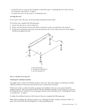
... the rack. 2. Use the Allen wrench that was supplied with the rack to the floor. To install the second stabilizer bracket on the floor. The mechanical contractor must be bolted to tighten the mounting screws alternately until they are tight. 1 Rack front (base) 2 Stabilizer mounting screws 3 Stabilizer bracket 4 Rack rear (base) Figure 3. This section describes how to meet the requirements for a concrete floor. Obtain the services of the rack, repeat...
... the rack. 2. Use the Allen wrench that was supplied with the rack to the floor. To install the second stabilizer bracket on the floor. The mechanical contractor must be bolted to tighten the mounting screws alternately until they are tight. 1 Rack front (base) 2 Stabilizer mounting screws 3 Stabilizer bracket 4 Rack rear (base) Figure 3. This section describes how to meet the requirements for a concrete floor. Obtain the services of the rack, repeat...

User Guide
Page 17
... stabilizer bracket has been Racks and rack features 5 The hardware mounting kit contains the following items: v 4 Rack-mounting bolts v 4 Thin washers v 8 Plastic isolator bushings v 4 Thick washers v 4 Spacers 5. After the rack doors have been removed, go to help you are installed, remove the front and rear doors. If you locate the mounting locations for the stabilizer bracket. b. Removing the trim panels 3. If they are installing an ac-powered rack, temporarily install...
... stabilizer bracket has been Racks and rack features 5 The hardware mounting kit contains the following items: v 4 Rack-mounting bolts v 4 Thin washers v 8 Plastic isolator bushings v 4 Thick washers v 4 Spacers 5. After the rack doors have been removed, go to help you are installed, remove the front and rear doors. If you locate the mounting locations for the stabilizer bracket. b. Removing the trim panels 3. If they are installing an ac-powered rack, temporarily install...

User Guide
Page 19
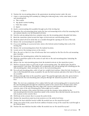
... brackets within the marked areas. 19. Remove the rack-mounting bolt assemblies. 14. 1 Rack-mounting bolt 2 Thin washer 3 Top plastic isolator bushing 4 Thick washer 5 Spacer 6 Jam nut 7 Leveling foot 8 Lower plastic isolator bushing (Used only on dc powered systems) 9 Mounting plate 10 Threaded hole (Used to secure the rack to stabilizer bracket.) 11 Anchor bolt hole 12 Traced pattern (Pattern to be approximately 1-inch...
... brackets within the marked areas. 19. Remove the rack-mounting bolt assemblies. 14. 1 Rack-mounting bolt 2 Thin washer 3 Top plastic isolator bushing 4 Thick washer 5 Spacer 6 Jam nut 7 Leveling foot 8 Lower plastic isolator bushing (Used only on dc powered systems) 9 Mounting plate 10 Threaded hole (Used to secure the rack to stabilizer bracket.) 11 Anchor bolt hole 12 Traced pattern (Pattern to be approximately 1-inch...
User Guide
Page 23
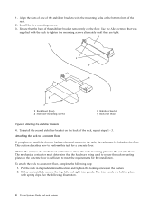
... stabilizer bracket within the marked area on the concrete floor. 25. Create a rack-mounting bolt assembly by adding the following items, in the approximate mounting location under the four rack-mounting bolts so that the mounting bolts are accessible. 23. a. Remove the rack-mounting bolt assemblies. 14. Insert a rack-mounting bolt assembly through to the concrete floor directly beneath, and mark the hole locations on the raised-floor panel. The...
... stabilizer bracket within the marked area on the concrete floor. 25. Create a rack-mounting bolt assembly by adding the following items, in the approximate mounting location under the four rack-mounting bolts so that the mounting bolts are accessible. 23. a. Remove the rack-mounting bolt assemblies. 14. Insert a rack-mounting bolt assembly through to the concrete floor directly beneath, and mark the hole locations on the raised-floor panel. The...

User Guide
Page 24
... rack-mounting bolts with rack-to-rack attachment kit" on page 33. Adjust the leveling feet downward as needed until the rack is level, tighten the jam nuts against the base of the rack. 37. Turn each of the raised floor and through a leveling foot. 34. Tighten the locking screw on top of the bolt assemblies through to the concrete floor. 31. Using your rack, install...
... rack-mounting bolts with rack-to-rack attachment kit" on page 33. Adjust the leveling feet downward as needed until the rack is level, tighten the jam nuts against the base of the rack. 37. Turn each of the raised floor and through a leveling foot. 34. Tighten the locking screw on top of the bolt assemblies through to the concrete floor. 31. Using your rack, install...
User Guide
Page 26
... and shows how these components relate to the floor and the stabilizer brackets have been removed. Install the ground lug in this section to install ac outlets on the front or the rear of the rack. Place the star washer onto the ground lug...number of ac outlets that the number and location of the ground cable onto the ground lug. 14 Power Systems: Racks and rack features Place the lug on the short end of ac outlets to the floor, the stabilizer brackets must be used to perform this task. Attention: The front and rear ac outlet-mounting plates mount through the mounting...
... and shows how these components relate to the floor and the stabilizer brackets have been removed. Install the ground lug in this section to install ac outlets on the front or the rear of the rack. Place the star washer onto the ground lug...number of ac outlets that the number and location of the ground cable onto the ground lug. 14 Power Systems: Racks and rack features Place the lug on the short end of ac outlets to the floor, the stabilizer brackets must be used to perform this task. Attention: The front and rear ac outlet-mounting plates mount through the mounting...

User Guide
Page 29
... can support a dc power configuration for systems that require dc power. If they are installed, remove the four screws from the customer's source -48 V dc to the bus bars in the power distribution panel. If you do not want any ac outlets installed on the front or rear ac outlet-mounting plate, perform only "Attaching the rack to install front or rear ac outlet-mounting...
... can support a dc power configuration for systems that require dc power. If they are installed, remove the four screws from the customer's source -48 V dc to the bus bars in the power distribution panel. If you do not want any ac outlets installed on the front or rear ac outlet-mounting plate, perform only "Attaching the rack to install front or rear ac outlet-mounting...
User Guide
Page 39
...used as shelves or work spaces. v Each rack cabinet might cause the rack to become unstable if you pull out more than one rack cabinet into a power device installed in the rack cabinet when directed to the rack. v To avoid hazardous conditions due to prevent an electrical shock. v Rack-mounted devices are not attached to disconnect power during servicing...correctly wired could place hazardous voltage on the metal parts of the system or the devices that is not blocked or reduced on any drawer or feature if the rack stabilizer brackets are not to the system. DANGER Observe the ...
...used as shelves or work spaces. v Each rack cabinet might cause the rack to become unstable if you pull out more than one rack cabinet into a power device installed in the rack cabinet when directed to the rack. v To avoid hazardous conditions due to prevent an electrical shock. v Rack-mounted devices are not attached to disconnect power during servicing...correctly wired could place hazardous voltage on the metal parts of the system or the devices that is not blocked or reduced on any drawer or feature if the rack stabilizer brackets are not to the system. DANGER Observe the ...

User Guide
Page 40
Bracket - Screw - Rack lock - Two keys 2 Two security slide bars 28 Power Systems: Racks and rack features Verify the inventory in this section to install the rack security kit. To install a rack security kit (feature 6580) that consists of the related hardware components and shows how these components relate to each other. Read the "Rack safety notices" on page 26. 2. Use the procedure in the...
Bracket - Screw - Rack lock - Two keys 2 Two security slide bars 28 Power Systems: Racks and rack features Verify the inventory in this section to install the rack security kit. To install a rack security kit (feature 6580) that consists of the related hardware components and shows how these components relate to each other. Read the "Rack safety notices" on page 26. 2. Use the procedure in the...
User Guide
Page 43
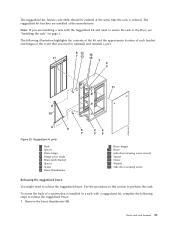
... rack is installed in this section to release the ruggedized brace. Racks and rack features 31 The ruggedized kit, feature code 6080, should be ordered at the manufacturer. Figure 29. Remove the brace thumbscrew (8). Ruggedized kit parts 1 Rack 2 Spacer 3 Brace hinge 4 Hinge pivot studs 5 Brace latch bracket 6 Spacer 7 Screw 8 Brace thumbscrew 9 Brace hinges 10 Brace 11 Side-door securing screw mount 12 Spacer 13 Screw...
... rack is installed in this section to release the ruggedized brace. Racks and rack features 31 The ruggedized kit, feature code 6080, should be ordered at the manufacturer. Figure 29. Remove the brace thumbscrew (8). Ruggedized kit parts 1 Rack 2 Spacer 3 Brace hinge 4 Hinge pivot studs 5 Brace latch bracket 6 Spacer 7 Screw 8 Brace thumbscrew 9 Brace hinges 10 Brace 11 Side-door securing screw mount 12 Spacer 13 Screw...
User Guide
Page 51
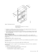
... side of the rack. Install rack filler panels to step 5 on page 40. Tip: Removing the rack doors and side panels might make installation easier. To install the PDU model in a single EIA vertical mounting space in the 7014-T00 and 7014-T42 racks. This step ensures that are plugged into it. Racks and rack features 39 Power distribution unit The power distribution unit (PDU) or power distribution unit plus...
... side of the rack. Install rack filler panels to step 5 on page 40. Tip: Removing the rack doors and side panels might make installation easier. To install the PDU model in a single EIA vertical mounting space in the 7014-T00 and 7014-T42 racks. This step ensures that are plugged into it. Racks and rack features 39 Power distribution unit The power distribution unit (PDU) or power distribution unit plus...
User Guide
Page 54
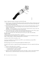
...: "Setting up power monitoring using the PDU+" on the power cord with the PDU model 8. Choose one of the PDU+ as shown in the rack to step 5 on page 43. Attention: To prevent damage to a power device and other power cables neatly, and secure the power cables with step 3. 3. Tip: Removing the rack doors and side panels might make installation easier. v To install the...
...: "Setting up power monitoring using the PDU+" on the power cord with the PDU model 8. Choose one of the PDU+ as shown in the rack to step 5 on page 43. Attention: To prevent damage to a power device and other power cables neatly, and secure the power cables with step 3. 3. Tip: Removing the rack doors and side panels might make installation easier. v To install the...
User Guide
Page 56
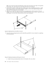
... of the long mounting brackets helps clear the brackets from the rack flanges. 8. Pushing in slightly on the rack flanges. Use screws that were provided with the outside of the PDU model with the short mounting brackets with the rack mounting kit. Attaching the brackets and filler panel to the rack cabinet by completing the following steps: Figure 45. Figure 44. Adjust the long mounting brackets (A) to fit the...
... of the long mounting brackets helps clear the brackets from the rack flanges. 8. Pushing in slightly on the rack flanges. Use screws that were provided with the outside of the PDU model with the short mounting brackets with the rack mounting kit. Attaching the brackets and filler panel to the rack cabinet by completing the following steps: Figure 45. Figure 44. Adjust the long mounting brackets (A) to fit the...
User Guide
Page 61
...trap alerts to specified users when specific events occur, complete the following steps: 1. Use this page to set the PDU+ IP address, gateway address, subnet mask, and Domain Name System (DNS) address. 3. Click Control to add the e-mail addresses. Click Access Control to analyze problems with an SNMP ... a record of the input power and output power of the events that cause the traps. 3. From the main status page, in the left navigation pane, click System. 2. Click Email Notification under System to create a list of up to create a list of users or workstations who will be ...
...trap alerts to specified users when specific events occur, complete the following steps: 1. Use this page to set the PDU+ IP address, gateway address, subnet mask, and Domain Name System (DNS) address. 3. Click Control to add the e-mail addresses. Click Access Control to analyze problems with an SNMP ... a record of the input power and output power of the events that cause the traps. 3. From the main status page, in the left navigation pane, click System. 2. Click Email Notification under System to create a list of up to create a list of users or workstations who will be ...