
User Guide
Page 5
...'s new in Racks and rack features 1 Installing the rack 1 7014-T00 and 7014-T42 racks 1 Installing the 7014-T00 and 7014-T42 racks 1 Completing a parts inventory 2 Positioning the rack 2 Leveling...7014-T00 or 7014-T42 side panels 21 Removing a 7014-T00 or 7014-T42 side panel 21 Replacing a 7014-T00 or 7014-T42 side panel 22 Removing and replacing 7014-T00 or 7014-T42 trim panels 22 Removing the 7014-T00 or 7014-T42 trim panels 22 Replacing the 7014-T00 or 7014-T42...unit 39 Installing the PDU or PDU+ in the side of a rack 39 Setting up power monitoring using the PDU 45 7953-94X and...
...'s new in Racks and rack features 1 Installing the rack 1 7014-T00 and 7014-T42 racks 1 Installing the 7014-T00 and 7014-T42 racks 1 Completing a parts inventory 2 Positioning the rack 2 Leveling...7014-T00 or 7014-T42 side panels 21 Removing a 7014-T00 or 7014-T42 side panel 21 Replacing a 7014-T00 or 7014-T42 side panel 22 Removing and replacing 7014-T00 or 7014-T42 trim panels 22 Removing the 7014-T00 or 7014-T42 trim panels 22 Replacing the 7014-T00 or 7014-T42...unit 39 Installing the PDU or PDU+ in the side of a rack 39 Setting up power monitoring using the PDU 45 7953-94X and...
User Guide
Page 13
.... © Copyright IBM Corp. 2010, 2013 1 If you are installing a rack security kit in each system model topic. - You might be charged a fee by the service provider for the 7014-T00 and 7014-T42 racks and the 7953-94X and 7953-94Y racks. 7014-T00 and 7014-T42 racks Use this service... changes were made to the same information in Common procedures for both PDU and PDU+ models. Installing the rack Use this information to find the planning and installation procedures for this information to install the 7014-T00 and 7014-T42 racks and to install racks and rack features. What's new in ...
.... © Copyright IBM Corp. 2010, 2013 1 If you are installing a rack security kit in each system model topic. - You might be charged a fee by the service provider for the 7014-T00 and 7014-T42 racks and the 7953-94X and 7953-94Y racks. 7014-T00 and 7014-T42 racks Use this service... changes were made to the same information in Common procedures for both PDU and PDU+ models. Installing the rack Use this information to find the planning and installation procedures for this information to install the 7014-T00 and 7014-T42 racks and to install racks and rack features. What's new in ...
User Guide
Page 51
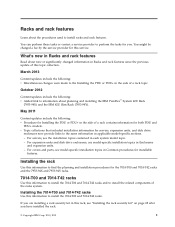
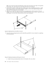
...how to cover open areas at the right and left side of the rack, complete the following options to install your PDU model: v To install the PDU, go to monitor the individual power loads of the rack. 5. Racks and rack features 39 Install the screws (B) ...PDU or PDU+ in the side of the top cover. Install rack filler panels to install the power distribution unit (PDU) or power distribution unit plus (PDU+) can be installed in the side of the rack. Power distribution unit The power distribution unit (PDU) or power distribution unit plus (PDU+) vertically in the 7014-T00 and 7014-T42...
...how to cover open areas at the right and left side of the rack, complete the following options to install your PDU model: v To install the PDU, go to monitor the individual power loads of the rack. 5. Racks and rack features 39 Install the screws (B) ...PDU or PDU+ in the side of the top cover. Install rack filler panels to install the power distribution unit (PDU) or power distribution unit plus (PDU+) can be installed in the side of the rack. Power distribution unit The power distribution unit (PDU) or power distribution unit plus (PDU+) vertically in the 7014-T00 and 7014-T42...

User Guide
Page 52
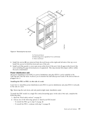
.... 5. Attach nut clips (A) to the rack mounting flanges 40 Power Systems: Racks and rack features Figure 38. Attach the brackets (A) to the front of the PDU+. 3. Make sure that you attach the brackets so that were provided with the rack mounting kit. Use nut clips that the power outlets face the.... Use screws that were provided with two M3x5 screws (B) per bracket. Attaching nut clips to the four locations on the rack mounting flanges where the PDU model will be attached.
.... 5. Attach nut clips (A) to the rack mounting flanges 40 Power Systems: Racks and rack features Figure 38. Attach the brackets (A) to the front of the PDU+. 3. Make sure that you attach the brackets so that were provided with the rack mounting kit. Use nut clips that the power outlets face the.... Use screws that were provided with two M3x5 screws (B) per bracket. Attaching nut clips to the four locations on the rack mounting flanges where the PDU model will be attached.

User Guide
Page 53
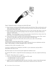
...clips in the following figure. Use screws that was provided with four M5 screws (A) as necessary for key alignment. If the PDU model was provided with the PDU model with the rack mounting kit. Align the connector on the power cord (A) that were provided with the connector on the ...front of the unit (A), turning as shown in the rack mounting flanges with a detached power cord, connect the power cord now. 6. Aligning the PDU+ with the opening in the side of the rack Attention: You must disconnect the main input power before connecting or disconnecting the input power cord...
...clips in the following figure. Use screws that was provided with four M5 screws (A) as necessary for key alignment. If the PDU model was provided with the PDU model with the rack mounting kit. Align the connector on the power cord (A) that were provided with the connector on the ...front of the unit (A), turning as shown in the rack mounting flanges with a detached power cord, connect the power cord now. 6. Aligning the PDU+ with the opening in the side of the rack Attention: You must disconnect the main input power before connecting or disconnecting the input power cord...
User Guide
Page 54
...in the side of the rack. 42 Power Systems: Racks and rack features Related concepts: "Setting up power monitoring using the PDU+" on the power cord with the PDU model. 9. Aligning the connector on page 45 You can monitor the power status for that is connected to the power distribution unit...way. Use the provided cable straps to a power device and other power cables neatly, and secure the power cables with step 3. 3. To install the PDU model in a single EIA horizontal mounting space in the rack, if the power cord must exit the rack to connect to a properly wired and grounded...
...in the side of the rack. 42 Power Systems: Racks and rack features Related concepts: "Setting up power monitoring using the PDU+" on the power cord with the PDU model. 9. Aligning the connector on page 45 You can monitor the power status for that is connected to the power distribution unit...way. Use the provided cable straps to a power device and other power cables neatly, and secure the power cables with step 3. 3. To install the PDU model in a single EIA horizontal mounting space in the rack, if the power cord must exit the rack to connect to a properly wired and grounded...

User Guide
Page 55
...screws (B) with the rack mounting kit. Aligning the vertical-mounting brackets to the front of the PDU model, and attach the brackets to the middle hole of the EIA on each side of the...rack. Racks and rack features 43 At the rear of the rack, attach nut clips to the PDU+ with two M3x5 screws (B) per bracket. Figure 43. Use nut clips that is the size of a single... EIA in the rear of the PDU+ 4. Use screws that were provided with the rack mounting kit. 5. Use screws that were provided with the rack...
...screws (B) with the rack mounting kit. Aligning the vertical-mounting brackets to the front of the PDU model, and attach the brackets to the middle hole of the EIA on each side of the...rack. Racks and rack features 43 At the rear of the rack, attach nut clips to the PDU+ with two M3x5 screws (B) per bracket. Figure 43. Use nut clips that is the size of a single... EIA in the rear of the PDU+ 4. Use screws that were provided with the rack mounting kit. 5. Use screws that were provided with the rack...
User Guide
Page 56
...front of nut clips to the specified EIA locations. Use two M6 screws (A) per bracket to attach the brackets to fit the depth of the PDU model with the short mounting brackets with the rack mounting kit. Figure 44. Align the end of the rack cabinet. 44 Power Systems: Racks and... the brackets from the rack flanges. 8. Attaching the brackets and filler panel to the rack cabinet by completing the following steps: Figure 45. Hold the PDU model at a slight angle and carefully insert it into a mounting space that were provided with the rack mounting kit. 7. Use cage nuts that is a ...
...front of nut clips to the specified EIA locations. Use two M6 screws (A) per bracket to attach the brackets to fit the depth of the PDU model with the short mounting brackets with the rack mounting kit. Figure 44. Align the end of the rack cabinet. 44 Power Systems: Racks and... the brackets from the rack flanges. 8. Attaching the brackets and filler panel to the rack cabinet by completing the following steps: Figure 45. Hold the PDU model at a slight angle and carefully insert it into a mounting space that were provided with the rack mounting kit. 7. Use cage nuts that is a ...
User Guide
Page 57
... and secure the power cables with a detached power cord, connect the power cord now. Use screws that is set up power monitoring using the PDU+: You can monitor the power status for key alignment. Align the connector on the power cord (A) that the long mounting brackets are available through the...the connector on the outside of the rack flanges. Route all of the unit (A), turning as necessary for any device that were provided with the PDU model. 12. Align the blank filler panel (B) on the front of the other connected devices, always connect the power device to an authorized ...
... and secure the power cables with a detached power cord, connect the power cord now. Use screws that is set up power monitoring using the PDU+: You can monitor the power status for key alignment. Align the connector on the power cord (A) that the long mounting brackets are available through the...the connector on the outside of the rack flanges. Route all of the unit (A), turning as necessary for any device that were provided with the PDU model. 12. Align the blank filler panel (B) on the front of the other connected devices, always connect the power device to an authorized ...

User Guide
Page 58
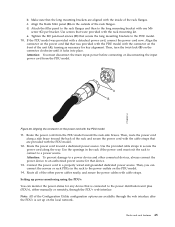
...Receivers Configure remote network management system (NMS) servers to use the IBM Distributed power interconnect (DPI) Configuration Utility to the PDU+. 5. Connect the DB9-to-RJ-45 cable that is connected to configure the PDU+ after the IP address is 9600 and that you to install...OK. Type the default password, passw0rd (all lowercase letters with the PDU+, complete the following options are shown on the Configuration Utility main menu: IBM DPI Settings When you select IBM DPI Settings, the IBM DPI Configuration Utility window is connected to configure the power distribution unit ...
...Receivers Configure remote network management system (NMS) servers to use the IBM Distributed power interconnect (DPI) Configuration Utility to the PDU+. 5. Connect the DB9-to-RJ-45 cable that is connected to configure the PDU+ after the IP address is 9600 and that you to install...OK. Type the default password, passw0rd (all lowercase letters with the PDU+, complete the following options are shown on the Configuration Utility main menu: IBM DPI Settings When you select IBM DPI Settings, the IBM DPI Configuration Utility window is connected to configure the power distribution unit ...

User Guide
Page 59
... Set Superuser Name and Password Set the user name and password of the PDU+ power outlets and input status: v The left pane displays the menus and submenus for the PDU+. Set IBM DPI Information Configure the PDU+ logging interval, refresh rate, and custom name fields for Set the IP... Address, Gateway Address and MIB System Group. Restart HD-PDU Restart the PDU+. The PDU+ provides a graphical user interface that you can ...
... Set Superuser Name and Password Set the user name and password of the PDU+ power outlets and input status: v The left pane displays the menus and submenus for the PDU+. Set IBM DPI Information Configure the PDU+ logging interval, refresh rate, and custom name fields for Set the IP... Address, Gateway Address and MIB System Group. Restart HD-PDU Restart the PDU+. The PDU+ provides a graphical user interface that you can ...
User Guide
Page 60
...name and password: You can set the date and time manually, synchronize it with the computer time, or synchronize it with configuring the PDU+. Identifying the PDU+ and Web/SNMP card: You can change the date and time, complete the following steps: 1. Click Multi-User to add users...will use a web browser to assist you connect an optional environmental monitored probe, the temperature and humidity environment conditions are displayed. To change the PDU+ settings. From the main status page, in the left navigation pane, click System. 2. You can change the superuser name and password, ...
...name and password: You can set the date and time manually, synchronize it with the computer time, or synchronize it with configuring the PDU+. Identifying the PDU+ and Web/SNMP card: You can change the date and time, complete the following steps: 1. Click Multi-User to add users...will use a web browser to assist you connect an optional environmental monitored probe, the temperature and humidity environment conditions are displayed. To change the PDU+ settings. From the main status page, in the left navigation pane, click System. 2. You can change the superuser name and password, ...
User Guide
Page 61
...left navigation pane, click System. 2. Use this page to analyze problems with network equipment. To view or change the network information for the PDU+, for sending mail alerts. History and event log summaries: The Logs menu provides a detailed description of the events that cause the traps. ...3. To view the complete record of the PDU+, complete the following steps: 1. Use the Email Receivers Table to configure TCP/IP settings. 4. Viewing the history log: You can specify the...
...left navigation pane, click System. 2. Use this page to analyze problems with network equipment. To view or change the network information for the PDU+, for sending mail alerts. History and event log summaries: The Logs menu provides a detailed description of the events that cause the traps. ...3. To view the complete record of the PDU+, complete the following steps: 1. Use the Email Receivers Table to configure TCP/IP settings. 4. Viewing the history log: You can specify the...