
User Guide
Page 5
... source 17 Removing and replacing 7014-T00 or 7014-T42 side panels 21 Removing a 7014-T00 or 7014-T42 side panel 21 Replacing a 7014-T00 or 7014-T42 side panel 22 Removing and replacing 7014-T00 or 7014-T42 trim panels 22 Removing the 7014-T00 or 7014-T42 trim panels 22 Replacing the 7014-T00 or 7014-T42 trim panels 23 Attaching the rack doors 24 Attaching a high...
... source 17 Removing and replacing 7014-T00 or 7014-T42 side panels 21 Removing a 7014-T00 or 7014-T42 side panel 21 Replacing a 7014-T00 or 7014-T42 side panel 22 Removing and replacing 7014-T00 or 7014-T42 trim panels 22 Removing the 7014-T00 or 7014-T42 trim panels 22 Replacing the 7014-T00 or 7014-T42 trim panels 23 Attaching the rack doors 24 Attaching a high...
User Guide
Page 7
...clearly understand any time you must first become familiar with the product. Replacement or additional copies of an IT equipment rack. © Copyright IBM Corp. 2010, 2013 v World Trade safety information Several countries require the safety information contained in printed documentation, on... Das Produkt ist nicht für den Einsatz an Bildschirmarbeitsplätzen im Sinne § 2 der Bildschirmarbeitsverordnung geeignet. Laser compliance IBM servers may be printed throughout this guide: v DANGER notices call attention to a situation that is included in the publications package ...
...clearly understand any time you must first become familiar with the product. Replacement or additional copies of an IT equipment rack. © Copyright IBM Corp. 2010, 2013 v World Trade safety information Several countries require the safety information contained in printed documentation, on... Das Produkt ist nicht für den Einsatz an Bildschirmarbeitsplätzen im Sinne § 2 der Bildschirmarbeitsverordnung geeignet. Laser compliance IBM servers may be printed throughout this guide: v DANGER notices call attention to a situation that is included in the publications package ...
User Guide
Page 8
DANGER When working on the devices. (D005) DANGER vi Power Systems: Racks and rack features v Do not connect or disconnect any cables or perform installation, maintenance, or reconfiguration of fire, water, or structural damage. To remove all hazardous voltages... otherwise). 2. v Connect all cables from the outlets. 3. To avoid a shock hazard: v Connect power to properly wired outlets. Ensure that will be equipped with the IBM provided power cord. Remove the power cords from the devices. v Connect any equipment when there is evidence of this product to this product or attached...
DANGER When working on the devices. (D005) DANGER vi Power Systems: Racks and rack features v Do not connect or disconnect any cables or perform installation, maintenance, or reconfiguration of fire, water, or structural damage. To remove all hazardous voltages... otherwise). 2. v Connect all cables from the outlets. 3. To avoid a shock hazard: v Connect power to properly wired outlets. Ensure that will be equipped with the IBM provided power cord. Remove the power cords from the devices. v Connect any equipment when there is evidence of this product to this product or attached...

User Guide
Page 9
...Observe the following precautions when working on or around your rack-mounted devices. v Always install stabilizer brackets on the rack cabinet. Be sure to disconnect all power cords in a rack where the internal rack ambient temperatures will exceed the manufacturer's recommended ambient temperature for... servicing unless specified by the manufacturer. v Always lower the leveling pads on the rack cabinet. To provide the correct power connection to a rack, refer to the rack. v (For sliding drawers.) Do not pull out or install any side, front, or ...
...Observe the following precautions when working on or around your rack-mounted devices. v Always install stabilizer brackets on the rack cabinet. Be sure to disconnect all power cords in a rack where the internal rack ambient temperatures will exceed the manufacturer's recommended ambient temperature for... servicing unless specified by the manufacturer. v Always lower the leveling pads on the rack cabinet. To provide the correct power connection to a rack, refer to the rack. v (For sliding drawers.) Do not pull out or install any side, front, or ...
User Guide
Page 10
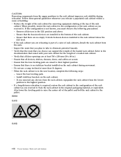
...hazards. v Verify that the route that you choose can support the weight of the loaded rack cabinet. v When the rack cabinet is required, restore the rack cabinet to raise the casters off of the rack cabinet as you must observe the following steps: - v If a long-distance relocation ...drawers, doors, and cables are raised to the highest position. Lower the four leveling pads. - Pack the rack cabinet in the bottom of rack cabinets, detach the rack cabinet from the lowest position to their highest position. Follow these general guidelines whenever you are installed in the ...
...hazards. v Verify that the route that you choose can support the weight of the loaded rack cabinet. v When the rack cabinet is required, restore the rack cabinet to raise the casters off of the rack cabinet as you must observe the following steps: - v If a long-distance relocation ...drawers, doors, and cables are raised to the highest position. Lower the four leveling pads. - Pack the rack cabinet in the bottom of rack cabinets, detach the rack cabinet from the lowest position to their highest position. Follow these general guidelines whenever you are installed in the ...
User Guide
Page 12
... to connect these interfaces metallically to intrabuilding or unexposed wiring or cabling only. x Power Systems: Racks and rack features Note the following : v Network telecommunications facilities v Locations where the NEC (National Electrical Code...) applies The intrabuilding ports of this reason, never look into the end of this equipment must be shielded and grounded at greater than 100°C (212°F) v ___ Repair or disassemble Exchange only with the IBM...
... to connect these interfaces metallically to intrabuilding or unexposed wiring or cabling only. x Power Systems: Racks and rack features Note the following : v Network telecommunications facilities v Locations where the NEC (National Electrical Code...) applies The intrabuilding ports of this reason, never look into the end of this equipment must be shielded and grounded at greater than 100°C (212°F) v ___ Repair or disassemble Exchange only with the IBM...
User Guide
Page 13
...™ System 42U Rack (7953-94X) and the IBM 42U Slim Rack (7953-94Y). For servers, see "Installing the rack security kit" on page 28 after you have installed the rack. © Copyright IBM Corp. 2010, 2013 1 If you . What's new in Racks and rack features Read about the procedures used to install the 7014-T00 and 7014-T42 racks. October 2012...
...™ System 42U Rack (7953-94X) and the IBM 42U Slim Rack (7953-94Y). For servers, see "Installing the rack security kit" on page 28 after you have installed the rack. © Copyright IBM Corp. 2010, 2013 1 If you . What's new in Racks and rack features Read about the procedures used to install the 7014-T00 and 7014-T42 racks. October 2012...
User Guide
Page 14
... of the parts on page 26. If there are incorrect, missing, or damaged parts, contact: v Your IBM reseller v IBM support (see Directory of worldwide contacts website at 1-800-300-8751 (United States only) Positioning the rack: Proper rack positioning is a good idea to perform this task. Country/region for contact information for the locking...
... of the parts on page 26. If there are incorrect, missing, or damaged parts, contact: v Your IBM reseller v IBM support (see Directory of worldwide contacts website at 1-800-300-8751 (United States only) Positioning the rack: Proper rack positioning is a good idea to perform this task. Country/region for contact information for the locking...
User Guide
Page 15
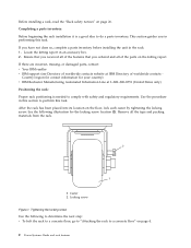
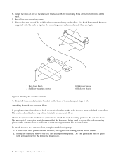
...-mounting plates. To attach the stabilizer brackets to the concrete floor beneath a raised floor" on each leveling foot downward until the rack is level, tighten the jam nuts against the base. 1 Rack Front (base) 2 Leveling Foot (quantity 4) 3 Jam Nut (quantity 4) Figure 2. If the front or back ac electrical outlets are used only...
...-mounting plates. To attach the stabilizer brackets to the concrete floor beneath a raised floor" on each leveling foot downward until the rack is level, tighten the jam nuts against the base. 1 Rack Front (base) 2 Leveling Foot (quantity 4) 3 Jam Nut (quantity 4) Figure 2. If the front or back ac electrical outlets are used only...
User Guide
Page 16
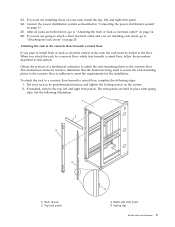
...a concrete floor: If you plan to install the front or back ac electrical outlets in the rack, the rack must determine that the hardware being used to secure the rack-mounting plates to the concrete floor is sufficient to the floor. The mechanical contractor must be bolted... the two mounting screws. 3. This section describes how to a concrete floor, complete the following illustration. 4 Power Systems: Racks and rack features Obtain the services of the rack, repeat steps 1 - 3. To attach the rack to perform this task for the installation. Align the slots of one of the...
...a concrete floor: If you plan to install the front or back ac electrical outlets in the rack, the rack must determine that the hardware being used to secure the rack-mounting plates to the concrete floor is sufficient to the floor. The mechanical contractor must be bolted... the two mounting screws. 3. This section describes how to a concrete floor, complete the following illustration. 4 Power Systems: Racks and rack features Obtain the services of the rack, repeat steps 1 - 3. To attach the rack to perform this task for the installation. Align the slots of one of the...

User Guide
Page 17
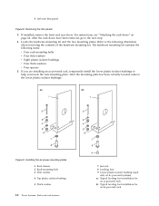
... with both hands and pull it away from the hinges. 4. Refer to the next substep. The hardware mounting kit contains the following steps: a. 1 Rack chassis 2 Top trim panel 3 Left-side trim panel 4 Right-side trim panel 5 Spring clip Figure 4. Unlock and open the door. Locate the ...hardware mounting kit and the two mounting plates. After the stabilizer bracket has been Racks and rack features 5 b. If you are installed, remove the front and rear doors. Removing the trim panels 3. If they are installing an ac-powered...
... with both hands and pull it away from the hinges. 4. Refer to the next substep. The hardware mounting kit contains the following steps: a. 1 Rack chassis 2 Top trim panel 3 Left-side trim panel 4 Right-side trim panel 5 Spring clip Figure 4. Unlock and open the door. Locate the ...hardware mounting kit and the two mounting plates. After the stabilizer bracket has been Racks and rack features 5 b. If you are installed, remove the front and rear doors. Removing the trim panels 3. If they are installing an ac-powered...

User Guide
Page 18
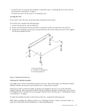
...into the mounting plate's threaded bolt holes. 6 Power Systems: Racks and rack features Create a rack-mounting bolt assembly by adding the following items, in the approximate mounting location under the four rack-mounting bolts so that the mounting bolts are centered directly over... mounting plates in the order listed, to each of the leveling feet. 9. Figure 5. Insert a rack-mounting bolt assembly through each rack-mounting bolt. Installing ac-power mounting plates 1 Rack chassis 2 Rack-mounting bolt 3 Thin washer 4 Top plastic isolator bushing 5 Thick washer 6 Spacer 7 Jam nut...
...into the mounting plate's threaded bolt holes. 6 Power Systems: Racks and rack features Create a rack-mounting bolt assembly by adding the following items, in the approximate mounting location under the four rack-mounting bolts so that the mounting bolts are centered directly over... mounting plates in the order listed, to each of the leveling feet. 9. Figure 5. Insert a rack-mounting bolt assembly through each rack-mounting bolt. Installing ac-power mounting plates 1 Rack chassis 2 Rack-mounting bolt 3 Thin washer 4 Top plastic isolator bushing 5 Thick washer 6 Spacer 7 Jam nut...

User Guide
Page 19
... into the concrete floor. Mark the floor at the center of all holes in the rear of both areas that are installing an ac-powered rack, remove the bottom isolator bushing from the marked locations. 16. Mark the plate bolt-down holes that were marked on the floor for the ...stabilizer bracket locations. 18. Racks and rack features 7 This depth allows the rack-mounting bolts enough room to the floor 11. Loosen each of the leveling feet. 15. At the marked location of the locking...
... into the concrete floor. Mark the floor at the center of all holes in the rear of both areas that are installing an ac-powered rack, remove the bottom isolator bushing from the marked locations. 16. Mark the plate bolt-down holes that were marked on the floor for the ...stabilizer bracket locations. 18. Racks and rack features 7 This depth allows the rack-mounting bolts enough room to the floor 11. Loosen each of the leveling feet. 15. At the marked location of the locking...

User Guide
Page 20
...: You must use a minimum of the anchor bolts and concrete anchors must be determined by the mechanical contractor who will be installing the rack-mounting plate. 27. Securely bolt the back stabilizer bracket to the concrete floor. 25. Tighten the locking screw on page 33. Adjusting ... Figure 7. Be sure that are accessible. Securely bolt the front stabilizer bracket to the concrete floor. Insert each stabilizer bracket bolt. When the rack is level. Otherwise, torque the four bolts to the concrete floor. Drill holes at least two suitable hole locations for each other), go to...
...: You must use a minimum of the anchor bolts and concrete anchors must be determined by the mechanical contractor who will be installing the rack-mounting plate. 27. Securely bolt the back stabilizer bracket to the concrete floor. 25. Tighten the locking screw on page 33. Adjusting ... Figure 7. Be sure that are accessible. Securely bolt the front stabilizer bracket to the concrete floor. Insert each stabilizer bracket bolt. When the rack is level. Otherwise, torque the four bolts to the concrete floor. Drill holes at least two suitable hole locations for each other), go to...
User Guide
Page 21
...trim panels. See the following steps: 1. 33. If you attach the rack to a concrete floor beneath a raised floor, complete the following illustration. 1 Rack chassis 2 Top trim panel 4 Right-side trim panel 5 Spring clip Racks and rack features 9 If installed, remove the top, left , and right trim...a raised floor, follow the procedure described in place with spring clips. Obtain the services of a mechanical contractor to attach the rack-mounting plates to meet the requirements for the installation. When you are held in this section. The trim panels are not installing ...
...trim panels. See the following steps: 1. 33. If you attach the rack to a concrete floor beneath a raised floor, complete the following illustration. 1 Rack chassis 2 Top trim panel 4 Right-side trim panel 5 Spring clip Racks and rack features 9 If installed, remove the top, left , and right trim...a raised floor, follow the procedure described in place with spring clips. Obtain the services of a mechanical contractor to attach the rack-mounting plates to meet the requirements for the installation. When you are held in this section. The trim panels are not installing ...
User Guide
Page 22
...Removing the trim panels 3. For instructions, see "Attaching the rack doors" on dc powered systems) ac Typical leveling foot installation for an ac-powered rack dc Typical leveling foot installation for an dc-powered rack Figure 9. Locate the hardware mounting kit and the two ...correctly located, remove the lower plastic isolator bushings. Installing the ac power-mounting plates 1 Rack chassis 2 Rack-mounting bolt 3 Thin washer 4 Top plastic isolator bushing 5 Thick washer 10 Power Systems: Racks and rack features 7 Jam nut 8 Leveling foot 9 Lower plastic isolator bushing (used only on ...
...Removing the trim panels 3. For instructions, see "Attaching the rack doors" on dc powered systems) ac Typical leveling foot installation for an ac-powered rack dc Typical leveling foot installation for an dc-powered rack Figure 9. Locate the hardware mounting kit and the two ...correctly located, remove the lower plastic isolator bushings. Installing the ac power-mounting plates 1 Rack chassis 2 Rack-mounting bolt 3 Thin washer 4 Top plastic isolator bushing 5 Thick washer 10 Power Systems: Racks and rack features 7 Jam nut 8 Leveling foot 9 Lower plastic isolator bushing (used only on ...
User Guide
Page 23
...-floor panel to be approximately 1-inch deep. Because some of the raised floor and through holes in each rack-mounting plate to securely attach the rack-mounting plate through holes allow the anchor bolts to the concrete floor. Position the rear stabilizer brackets within the... marked area on the casters. 17. 6 Spacer 6. Insert a rack-mounting bolt assembly through the opening in the rack-mounting plates (including the tapped holes). 20. If you are accessible through each of the leveling feet. 9. Mark ...
...-floor panel to be approximately 1-inch deep. Because some of the raised floor and through holes in each rack-mounting plate to securely attach the rack-mounting plate through holes allow the anchor bolts to the concrete floor. Position the rear stabilizer brackets within the... marked area on the casters. 17. 6 Spacer 6. Insert a rack-mounting bolt assembly through the opening in the rack-mounting plates (including the tapped holes). 20. If you are accessible through each of the leveling feet. 9. Mark ...

User Guide
Page 24
...you are connected as a suite (bolted to each bolt three to four rotations. 35. Using your rack, install the top, left, and right trim panel. 12 Power Systems: Racks and rack features Insert each stabilizer bracket. Replace all raised-floor panels that are not installing doors on your ...anchor bolts, secure the back stabilizer bracket on each caster. 36. When the rack is level. Otherwise, torque the four bolts to the floor 30. Align the rack-mounting bolts with rack-to-rack attachment kit" on dc-powered systems) 9 Stabilizer brackets 10 Threaded hole (used only...
...you are connected as a suite (bolted to each bolt three to four rotations. 35. Using your rack, install the top, left, and right trim panel. 12 Power Systems: Racks and rack features Insert each stabilizer bracket. Replace all raised-floor panels that are not installing doors on your ...anchor bolts, secure the back stabilizer bracket on each caster. 36. When the rack is level. Otherwise, torque the four bolts to the floor 30. Align the rack-mounting bolts with rack-to-rack attachment kit" on dc-powered systems) 9 Stabilizer brackets 10 Threaded hole (used only...
User Guide
Page 25
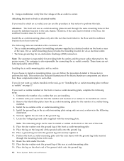
...are not going to attach a front electrical outlet, go to the receptacle case. For this system. Turn on page 24. Racks and rack features 13 Using a multimeter, check for less than 1 volt from the receptacle ground pin to any of a continuous grounding conductor...short. 6. c. Using a multimeter, check the resistance from the ground pin to test the grounding resistances. If you are installing rack doors, go to measure grounding resistance. The readings should check the ac outlets. Turn off the branch circuit breaker for infinite resistance...
...are not going to attach a front electrical outlet, go to the receptacle case. For this system. Turn on page 24. Racks and rack features 13 Using a multimeter, check for less than 1 volt from the receptacle ground pin to any of a continuous grounding conductor...short. 6. c. Using a multimeter, check the resistance from the ground pin to test the grounding resistances. If you are installing rack doors, go to measure grounding resistance. The readings should check the ac outlets. Turn off the branch circuit breaker for infinite resistance...
User Guide
Page 26
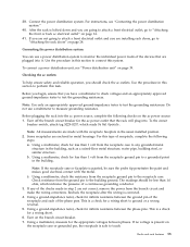
...The following items are correct. 3. The customer is also responsible for installing customer-supplied ac electrical outlets on the front or rear of the rack. Installing the ac outlet-mounting plates with your contractor that you are not field-replaceable units (FRUs). Remove the blank filler plates from the... the ground lug. 7. Place the star washer onto the ground lug of the ground cable onto the ground lug. 14 Power Systems: Racks and rack features Attaching the front or back ac electrical outlet: If you need to attach an ac outlet, you can follow the procedure detailed in...
...The following items are correct. 3. The customer is also responsible for installing customer-supplied ac electrical outlets on the front or rear of the rack. Installing the ac outlet-mounting plates with your contractor that you are not field-replaceable units (FRUs). Remove the blank filler plates from the... the ground lug. 7. Place the star washer onto the ground lug of the ground cable onto the ground lug. 14 Power Systems: Racks and rack features Attaching the front or back ac electrical outlet: If you need to attach an ac outlet, you can follow the procedure detailed in...