Service Guide
Page 91
...inner metal cover. Remove the rear connector panel (tailgate). See "Cooling duct - Remove the five screws, as described at "Rear cover - The new system board comes with a new battery. Open the side panel door. 4. See "Rear connector panel (tailgate) - Remove the cooling duct. See "Memory ...the fansink and slide it out toward the top. Disconnect all required jumpers and with factory default CMOS settings. Transfer modules to the SurePOS 500 Models 5x3 and 544/564. removing and replacing" on a table and remove the following parts: v Memory modules - See "...
...inner metal cover. Remove the rear connector panel (tailgate). See "Cooling duct - Remove the five screws, as described at "Rear cover - The new system board comes with a new battery. Open the side panel door. 4. See "Rear connector panel (tailgate) - Remove the cooling duct. See "Memory ...the fansink and slide it out toward the top. Disconnect all required jumpers and with factory default CMOS settings. Transfer modules to the SurePOS 500 Models 5x3 and 544/564. removing and replacing" on a table and remove the following parts: v Memory modules - See "...

Service Guide
Page 94
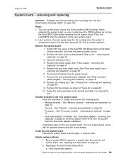
Reverse the steps to the left, as shown in "Rear connector panel (tailgate) - Remove the old battery from the slot A as you face the back of the machine. removing and replacing" on page 76. 6. Dual video adapter or jumper location 7. B A E JP32-35 JP29-31 D C JP7 Figure 47. Insert the new battery with the positive side to reassemble. 68 Remove the rear connector panel (tailgate) as described in Figure 47. Battery August 3, 2006 5.
Reverse the steps to the left, as shown in "Rear connector panel (tailgate) - Remove the old battery from the slot A as you face the back of the machine. removing and replacing" on page 76. 6. Dual video adapter or jumper location 7. B A E JP32-35 JP29-31 D C JP7 Figure 47. Insert the new battery with the positive side to reassemble. 68 Remove the rear connector panel (tailgate) as described in Figure 47. Battery August 3, 2006 5.