Owner's Manual
Page 2
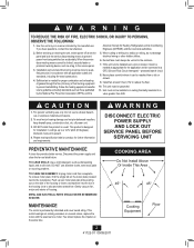
...Not Install Above Or Inside This Area 45° 45° Cooking Equipment Floor 2 41722-01 09/09/2011 TO CLEAN FAN ASSEMBLY: Unplug motor cord from being switched on the side of the housing or insert a screwdriver into wall(s) or ceiling, do not damage electrical... SUPPLY AND LOCK OUT SERVICE PANEL BEFORE SERVICING UNIT PREVENTATIVE MAINTENANCE A clean fan provides better service. Use this product in a manner intended by the National Fire Prevention Association (NFPA), and the 5. Gently vacuum fan, motor and interior of fuel burning equipment to the service panel. 3.
...Not Install Above Or Inside This Area 45° 45° Cooking Equipment Floor 2 41722-01 09/09/2011 TO CLEAN FAN ASSEMBLY: Unplug motor cord from being switched on the side of the housing or insert a screwdriver into wall(s) or ceiling, do not damage electrical... SUPPLY AND LOCK OUT SERVICE PANEL BEFORE SERVICING UNIT PREVENTATIVE MAINTENANCE A clean fan provides better service. Use this product in a manner intended by the National Fire Prevention Association (NFPA), and the 5. Gently vacuum fan, motor and interior of fuel burning equipment to the service panel. 3.
Owner's Manual
Page 6
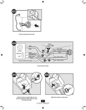
A15 F A16 2 1 F G• Install the wiring cover plate. A14 Fan Motor Night Light Light Black 2 Pin White White Red Night Light 3 Pin Black Light *Option *Option Fan & Main Light Together Ground Green A Bare Copper Black Main Switch 1 (AC In) White Red Switch 1 (AC In) Black Switch 2 (AC In) Connect wires as shown. Make sure all wiring connections are inside the box or under the wiring cover plate. 6 41722-01 09/09/2011 Tighten the wiring cover plate screw. A13 Pull wires through the strain relief.
A15 F A16 2 1 F G• Install the wiring cover plate. A14 Fan Motor Night Light Light Black 2 Pin White White Red Night Light 3 Pin Black Light *Option *Option Fan & Main Light Together Ground Green A Bare Copper Black Main Switch 1 (AC In) White Red Switch 1 (AC In) Black Switch 2 (AC In) Connect wires as shown. Make sure all wiring connections are inside the box or under the wiring cover plate. 6 41722-01 09/09/2011 Tighten the wiring cover plate screw. A13 Pull wires through the strain relief.
Owner's Manual
Page 9
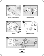
B18 Tighten screws. Screws are not provided. B15 B16 Insert screws, leaving space between the screw head and the joist. B17 Attach the rails onto the screws. B19 Fan Motor Night Light Light Black 2 Pin White White Red Night Light 3 Pin Black Light *Option *Option Fan & Main Light Together Ground Green A Bare Copper Black Main Switch 1 (AC In) White Red Switch 1 (AC In) Black Switch 2 (AC In) Connect wires as shown. 9 41722-01 09/09/2011 Pull wires through the strain relief.
B18 Tighten screws. Screws are not provided. B15 B16 Insert screws, leaving space between the screw head and the joist. B17 Attach the rails onto the screws. B19 Fan Motor Night Light Light Black 2 Pin White White Red Night Light 3 Pin Black Light *Option *Option Fan & Main Light Together Ground Green A Bare Copper Black Main Switch 1 (AC In) White Red Switch 1 (AC In) Black Switch 2 (AC In) Connect wires as shown. 9 41722-01 09/09/2011 Pull wires through the strain relief.
Owner's Manual
Page 11
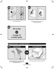
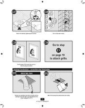
accessible from above C11 EXISTING FAN NO EXISTING FAN OR Remove an existing fan and check to make sure the opening is large enough to attach grille. Existing Construction - B27 ON OFF Test the motor. B28 Go to step E1 on the power source. If the motor does not run, check the plug connection. Use the motor housing as a template to mark position. 11 41722-01 09/09/2011 B26 Turn on page 18 to accommodate the new motor housing (9"x 9.75").
accessible from above C11 EXISTING FAN NO EXISTING FAN OR Remove an existing fan and check to make sure the opening is large enough to attach grille. Existing Construction - B27 ON OFF Test the motor. B28 Go to step E1 on the power source. If the motor does not run, check the plug connection. Use the motor housing as a template to mark position. 11 41722-01 09/09/2011 B26 Turn on page 18 to accommodate the new motor housing (9"x 9.75").
Owner's Manual
Page 14
... 41722-01 09/09/2011 C26 H H Connect wiring from the motor to the wiring cover plate. Make sure the wires are inside the box or under the wiring cover plate. C23 2 1 F Install the wiring cover plate. C22 Fan Motor Night Light Light Black 2 Pin White 3 Pin White Red Night ...Light Black Light *Option *Option Fan & Main Light Together Ground Green A Bare Copper Black Main Switch 1 (AC In) White Red Switch 1 ...
... 41722-01 09/09/2011 C26 H H Connect wiring from the motor to the wiring cover plate. Make sure the wires are inside the box or under the wiring cover plate. C23 2 1 F Install the wiring cover plate. C22 Fan Motor Night Light Light Black 2 Pin White 3 Pin White Red Night ...Light Black Light *Option *Option Fan & Main Light Together Ground Green A Bare Copper Black Main Switch 1 (AC In) White Red Switch 1 ...
Owner's Manual
Page 15
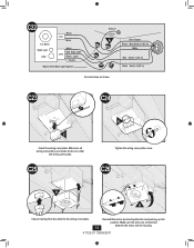
If the motor does not run, check the plug connection. Existing Construction - C29 ON C30 Go to step E1 OFF on the power source. accessible only from below D11 EXISTING FAN D12 E Remove an existing fan and check to make sure the opening is large enough to attach grille. Turn on page 18 to accommodate the new motor housing (9"x 9.75"). 15 Move the housing into position above the ceiling 41722-01 09/09/2011 Test the motor. C27 C28 I Secure the motor by tightening the 2 screws.
If the motor does not run, check the plug connection. Existing Construction - C29 ON C30 Go to step E1 OFF on the power source. accessible only from below D11 EXISTING FAN D12 E Remove an existing fan and check to make sure the opening is large enough to attach grille. Turn on page 18 to accommodate the new motor housing (9"x 9.75"). 15 Move the housing into position above the ceiling 41722-01 09/09/2011 Test the motor. C27 C28 I Secure the motor by tightening the 2 screws.
Owner's Manual
Page 16
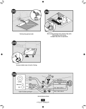
D15 D14 2 1 Attach existing ducting to be purchased. E Screw pre-loaded screws into joist or framing. If ducting does not fit securely, an adapter may need to duct connector. Tape joints. D13 Pull wires through strain relief. D16 Fan Motor Night Light Light Black 2 Pin White White Red Night Light 3 Pin Black Light *Option *Option Fan & Main Light Together Ground Green A Bare Copper Black Main Switch 1 (AC In) White Red Switch 1 (AC In) Black Switch 2 (AC In) Connect wires as shown. 16 41722-01 09/09/2011
D15 D14 2 1 Attach existing ducting to be purchased. E Screw pre-loaded screws into joist or framing. If ducting does not fit securely, an adapter may need to duct connector. Tape joints. D13 Pull wires through strain relief. D16 Fan Motor Night Light Light Black 2 Pin White White Red Night Light 3 Pin Black Light *Option *Option Fan & Main Light Together Ground Green A Bare Copper Black Main Switch 1 (AC In) White Red Switch 1 (AC In) Black Switch 2 (AC In) Connect wires as shown. 16 41722-01 09/09/2011
Owner's Manual
Page 20
...DURATION OF ANY IMPLIED WARRANTY, INCLUDING, BUT NOT LIMITED TO, ANY IMPLIED WARRANTY OF MERCHANTABILITY OR FITNESS FOR A PARTICULAR PURPOSE, IN RESPECT TO ANY HUNTER FAN BATH EXHAUST FAN MOTOR OR OTHER FAN PART, IS EXPRESSLY LIMITED TO THE PERIOD OF THE EXPRESS WARRANTY SET FORTH ABOVE FOR SUCH... defect in material or workmanship, labor and materials to repair the defect will be provided free of your bath exhaust fan to us. We will return your Hunter bath exhaust fan motor fails at our nearest service center or our Service Department in transit since we will not be properly packed to you...
...DURATION OF ANY IMPLIED WARRANTY, INCLUDING, BUT NOT LIMITED TO, ANY IMPLIED WARRANTY OF MERCHANTABILITY OR FITNESS FOR A PARTICULAR PURPOSE, IN RESPECT TO ANY HUNTER FAN BATH EXHAUST FAN MOTOR OR OTHER FAN PART, IS EXPRESSLY LIMITED TO THE PERIOD OF THE EXPRESS WARRANTY SET FORTH ABOVE FOR SUCH... defect in material or workmanship, labor and materials to repair the defect will be provided free of your bath exhaust fan to us. We will return your Hunter bath exhaust fan motor fails at our nearest service center or our Service Department in transit since we will not be properly packed to you...


