Owner's Manual
Page 2
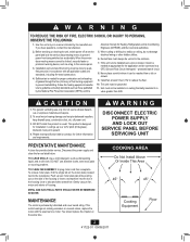
...to prevent backdrafting. WARNING TO REDUCE THE RISK OF FIRE, ELECTRIC SHOCK, OR INJURY TO PERSONS, OBSERVE THE FOLLOWING: 1. To avoid motor bearing damage and noisy/unbalanced impellers, keep drywall spray, construction dust, etc. Please read specification label on the side of the housing... PANEL BEFORE SERVICING UNIT PREVENTATIVE MAINTENANCE A clean fan provides better service. This unit must point upward. 4. Gently vacuum fan, motor and interior of fuel burning equipment to prevent power from receptacle. COOKING AREA Do Not Install Above Or Inside This Area 45°...
...to prevent backdrafting. WARNING TO REDUCE THE RISK OF FIRE, ELECTRIC SHOCK, OR INJURY TO PERSONS, OBSERVE THE FOLLOWING: 1. To avoid motor bearing damage and noisy/unbalanced impellers, keep drywall spray, construction dust, etc. Please read specification label on the side of the housing... PANEL BEFORE SERVICING UNIT PREVENTATIVE MAINTENANCE A clean fan provides better service. This unit must point upward. 4. Gently vacuum fan, motor and interior of fuel burning equipment to prevent power from receptacle. COOKING AREA Do Not Install Above Or Inside This Area 45°...
Owner's Manual
Page 4
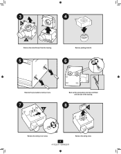
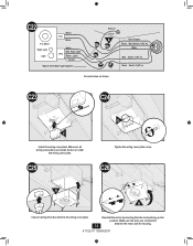
3 4 H E Remove the motor/blower from the housing. 5 Remove packing material. 6 Remove the pre-loaded screw tip covers. 7 G Back out the pre-loaded screw tips until flush with the side of the housing. 8 F Remove the wiring cover screw. 4 41722-01 09/09/2011 Remove the wiring cover.
3 4 H E Remove the motor/blower from the housing. 5 Remove packing material. 6 Remove the pre-loaded screw tip covers. 7 G Back out the pre-loaded screw tips until flush with the side of the housing. 8 F Remove the wiring cover screw. 4 41722-01 09/09/2011 Remove the wiring cover.
Owner's Manual
Page 6
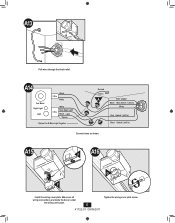
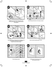
Make sure all wiring connections are inside the box or under the wiring cover plate. 6 41722-01 09/09/2011 Tighten the wiring cover plate screw. A13 Pull wires through the strain relief. A14 Fan Motor Night Light Light Black 2 Pin White White Red Night Light 3 Pin Black Light *Option *Option Fan & Main Light Together Ground Green A Bare Copper Black Main Switch 1 (AC In) White Red Switch 1 (AC In) Black Switch 2 (AC In) Connect wires as shown. A15 F A16 2 1 F G• Install the wiring cover plate.
Make sure all wiring connections are inside the box or under the wiring cover plate. 6 41722-01 09/09/2011 Tighten the wiring cover plate screw. A13 Pull wires through the strain relief. A14 Fan Motor Night Light Light Black 2 Pin White White Red Night Light 3 Pin Black Light *Option *Option Fan & Main Light Together Ground Green A Bare Copper Black Main Switch 1 (AC In) White Red Switch 1 (AC In) Black Switch 2 (AC In) Connect wires as shown. A15 F A16 2 1 F G• Install the wiring cover plate.
Owner's Manual
Page 7
A19 Connect wiring from the motor to the outside. If the motor does not run, check the plug connection. 7 41722-01 09/09/2011 Test the motor. A017 A18 H Connect 4" duct and vent to the wiring cover plate. If ducting does not fit securely, an adapter may need to be purchased. Make sure the wires are not pinched between the motor and the housing. Secure the motor by inserting the tabs and pushing up into position. Tape joints. A20 H I Reinstall the motor by tightening the 2 screws. A21 A22 ON OFF Turn on the power source.
A19 Connect wiring from the motor to the outside. If the motor does not run, check the plug connection. 7 41722-01 09/09/2011 Test the motor. A017 A18 H Connect 4" duct and vent to the wiring cover plate. If ducting does not fit securely, an adapter may need to be purchased. Make sure the wires are not pinched between the motor and the housing. Secure the motor by inserting the tabs and pushing up into position. Tape joints. A20 H I Reinstall the motor by tightening the 2 screws. A21 A22 ON OFF Turn on the power source.
Owner's Manual
Page 9
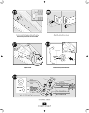
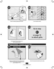
B17 Attach the rails onto the screws. Screws are not provided. Pull wires through the strain relief. B18 Tighten screws. B19 Fan Motor Night Light Light Black 2 Pin White White Red Night Light 3 Pin Black Light *Option *Option Fan & Main Light Together Ground Green A Bare Copper Black Main Switch 1 (AC In) White Red Switch 1 (AC In) Black Switch 2 (AC In) Connect wires as shown. 9 41722-01 09/09/2011 B15 B16 Insert screws, leaving space between the screw head and the joist.
B17 Attach the rails onto the screws. Screws are not provided. Pull wires through the strain relief. B18 Tighten screws. B19 Fan Motor Night Light Light Black 2 Pin White White Red Night Light 3 Pin Black Light *Option *Option Fan & Main Light Together Ground Green A Bare Copper Black Main Switch 1 (AC In) White Red Switch 1 (AC In) Black Switch 2 (AC In) Connect wires as shown. 9 41722-01 09/09/2011 B15 B16 Insert screws, leaving space between the screw head and the joist.
Owner's Manual
Page 10
... cover plate screw. B23 H Connect 4" duct and vent to the wiring cover plate. B25 H I Reinstall the motor by tightening the 2 screws. 41722-01 09/09/2011 B24 Connect wiring from the motor to the outside. If ducting does not fit securely, an adapter may need to be purchased. Make sure... all wiring connections are not pinched between the motor and the housing. 10 Secure the motor by inserting the tabs and pushing up into...
... cover plate screw. B23 H Connect 4" duct and vent to the wiring cover plate. B25 H I Reinstall the motor by tightening the 2 screws. 41722-01 09/09/2011 B24 Connect wiring from the motor to the outside. If ducting does not fit securely, an adapter may need to be purchased. Make sure... all wiring connections are not pinched between the motor and the housing. 10 Secure the motor by inserting the tabs and pushing up into...
Owner's Manual
Page 11
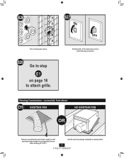
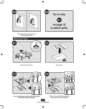
Use the motor housing as a template to accommodate the new motor housing (9"x 9.75"). Existing Construction - B28 Go to step E1 on the power source. accessible from above C11 EXISTING FAN NO EXISTING FAN OR Remove an existing fan and check to make sure the opening is large enough to mark position. 11 41722-01 09/09/2011 B27 ON OFF Test the motor. If the motor does not run, check the plug connection. B26 Turn on page 18 to attach grille.
Use the motor housing as a template to accommodate the new motor housing (9"x 9.75"). Existing Construction - B28 Go to step E1 on the power source. accessible from above C11 EXISTING FAN NO EXISTING FAN OR Remove an existing fan and check to make sure the opening is large enough to mark position. 11 41722-01 09/09/2011 B27 ON OFF Test the motor. If the motor does not run, check the plug connection. B26 Turn on page 18 to attach grille.
Owner's Manual
Page 14
C23 2 1 F Install the wiring cover plate. Make sure all wiring connections are not pinched 14 between the motor and the housing. 41722-01 09/09/2011 Make sure the wires are inside the box or under the wiring cover plate. C25 C24 G• ...Tighten the wiring cover plate screw. C26 H H Connect wiring from the motor to the wiring cover plate. Reinstall the motor by inserting the tabs and pushing up into position. C22 Fan Motor Night Light Light Black 2 Pin White 3 Pin White Red Night Light Black Light *Option *Option Fan...
C23 2 1 F Install the wiring cover plate. Make sure all wiring connections are not pinched 14 between the motor and the housing. 41722-01 09/09/2011 Make sure the wires are inside the box or under the wiring cover plate. C25 C24 G• ...Tighten the wiring cover plate screw. C26 H H Connect wiring from the motor to the wiring cover plate. Reinstall the motor by inserting the tabs and pushing up into position. C22 Fan Motor Night Light Light Black 2 Pin White 3 Pin White Red Night Light Black Light *Option *Option Fan...
Owner's Manual
Page 15
If the motor does not run, check the plug connection. Test the motor. C29 ON C30 Go to step E1 OFF on the power source. accessible only from below D11 EXISTING FAN D12 E Remove an existing fan and check to make sure the opening is large enough to attach grille. Turn on page 18 to accommodate the new motor housing (9"x 9.75"). 15 Move the housing into position above the ceiling 41722-01 09/09/2011 Existing Construction - C27 C28 I Secure the motor by tightening the 2 screws.
If the motor does not run, check the plug connection. Test the motor. C29 ON C30 Go to step E1 OFF on the power source. accessible only from below D11 EXISTING FAN D12 E Remove an existing fan and check to make sure the opening is large enough to attach grille. Turn on page 18 to accommodate the new motor housing (9"x 9.75"). 15 Move the housing into position above the ceiling 41722-01 09/09/2011 Existing Construction - C27 C28 I Secure the motor by tightening the 2 screws.
Owner's Manual
Page 16
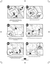
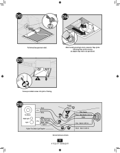
E Screw pre-loaded screws into joist or framing. D16 Fan Motor Night Light Light Black 2 Pin White White Red Night Light 3 Pin Black Light *Option *Option Fan & Main Light Together Ground Green A Bare Copper Black Main Switch 1 (AC In) White Red Switch 1 (AC In) Black Switch 2 (AC In) Connect wires as shown. 16 41722-01 09/09/2011 If ducting does not fit securely, an adapter may need to duct connector. D15 D14 2 1 Attach existing ducting to be purchased. Tape joints. D13 Pull wires through strain relief.
E Screw pre-loaded screws into joist or framing. D16 Fan Motor Night Light Light Black 2 Pin White White Red Night Light 3 Pin Black Light *Option *Option Fan & Main Light Together Ground Green A Bare Copper Black Main Switch 1 (AC In) White Red Switch 1 (AC In) Black Switch 2 (AC In) Connect wires as shown. 16 41722-01 09/09/2011 If ducting does not fit securely, an adapter may need to duct connector. D15 D14 2 1 Attach existing ducting to be purchased. Tape joints. D13 Pull wires through strain relief.
Owner's Manual
Page 17
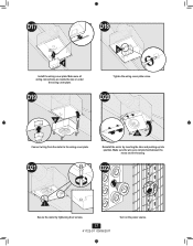
D21 H Reinstall the motor by tightening the 2 screws. 17 41722-01 09/09/2011 Turn on the power source. D19 D18 G• Tighten the wiring cover plate screw. D22 I Secure the motor by inserting the tabs and pushing up into position. D17 2 1 F Install the wiring cover plate. Make sure the wires are inside the box or under the wiring cover plate. D20 H Connect wiring from the motor to the wiring cover plate. Make sure all wiring connections are not pinched between the motor and the housing.
D21 H Reinstall the motor by tightening the 2 screws. 17 41722-01 09/09/2011 Turn on the power source. D19 D18 G• Tighten the wiring cover plate screw. D22 I Secure the motor by inserting the tabs and pushing up into position. D17 2 1 F Install the wiring cover plate. Make sure the wires are inside the box or under the wiring cover plate. D20 H Connect wiring from the motor to the wiring cover plate. Make sure all wiring connections are not pinched between the motor and the housing.
Owner's Manual
Page 18
D23 ON OFF Test the motor. Attaching the Grille E1 H M Remove the thumbscrews. D24 Go to step E1 on page 18 to attach grille. If the motor does not run, check the plug connection. E2 N Remove glass. Position the strain relief bracket between the plugs as shown, and screw into place. 18 41722-01 09/09/2011 E3 E4 H J L Connect wiring harness. DO NOT ALLOW THE FIXTURE TO HANG FROM THE WIRING HARNESS.
D23 ON OFF Test the motor. Attaching the Grille E1 H M Remove the thumbscrews. D24 Go to step E1 on page 18 to attach grille. If the motor does not run, check the plug connection. E2 N Remove glass. Position the strain relief bracket between the plugs as shown, and screw into place. 18 41722-01 09/09/2011 E3 E4 H J L Connect wiring harness. DO NOT ALLOW THE FIXTURE TO HANG FROM THE WIRING HARNESS.
Owner's Manual
Page 20
... WARRANTY OF MERCHANTABILITY OR FITNESS FOR A PARTICULAR PURPOSE, IN RESPECT TO ANY HUNTER FAN BATH EXHAUST FAN MOTOR OR OTHER FAN PART, IS EXPRESSLY LIMITED TO THE PERIOD OF THE EXPRESS WARRANTY SET FORTH ABOVE FOR SUCH MOTORS OR OTHER PARTS. This warranty is voided if your possession, or unreasonable use...exhaust fan except for parts and labor performed at our nearest service center or at our Service Department in Memphis, Tennessee. If your Hunter bath exhaust fan motor fails at any time within five years after the date of sale to you due to a defect in material or workmanship, we will...
... WARRANTY OF MERCHANTABILITY OR FITNESS FOR A PARTICULAR PURPOSE, IN RESPECT TO ANY HUNTER FAN BATH EXHAUST FAN MOTOR OR OTHER FAN PART, IS EXPRESSLY LIMITED TO THE PERIOD OF THE EXPRESS WARRANTY SET FORTH ABOVE FOR SUCH MOTORS OR OTHER PARTS. This warranty is voided if your possession, or unreasonable use...exhaust fan except for parts and labor performed at our nearest service center or at our Service Department in Memphis, Tennessee. If your Hunter bath exhaust fan motor fails at any time within five years after the date of sale to you due to a defect in material or workmanship, we will...


