
Installation Guide
Page 1
... fan and light kit. Position it will hold the outlet box and fan. 2-2. Fan Support System o Fan attaches directly to outlet box by wood screws and washers through the inner holes of lead wires extend from any hardware store or electrical supply house. 5-4. o Six inches of the outlet box. 4-4. Fan Support System Fan Support System Suitable Existing Fan Site Wiring Outlet Box Hunter Fan Company Step 2 Cut the Ceiling Hole 2-1. If NOT, install a support brace as walls or posts, within 30 inches of the fan blade...
... fan and light kit. Position it will hold the outlet box and fan. 2-2. Fan Support System o Fan attaches directly to outlet box by wood screws and washers through the inner holes of lead wires extend from any hardware store or electrical supply house. 5-4. o Six inches of the outlet box. 4-4. Fan Support System Fan Support System Suitable Existing Fan Site Wiring Outlet Box Hunter Fan Company Step 2 Cut the Ceiling Hole 2-1. If NOT, install a support brace as walls or posts, within 30 inches of the fan blade...

Owner's Manual
Page 1
For Your Records and Warranty Assistance For reference, also attach your receipt or a copy of your receipt to the manual. Date Purchased Where Purchased Type 2 Models Owner's Guide and Installation Manual English Español Form# 42437-01 20100608 ©2010 Hunter Fan Co. Model Name Model No.
For Your Records and Warranty Assistance For reference, also attach your receipt or a copy of your receipt to the manual. Date Purchased Where Purchased Type 2 Models Owner's Guide and Installation Manual English Español Form# 42437-01 20100608 ©2010 Hunter Fan Co. Model Name Model No.
Owner's Manual
Page 2
... instructions, and use a solid-state speed control with national and local electrical codes and ANSI/NFPA 70. Table Of Contents Preparing the Fan Site 3 1 • Getting Ready 6 2 • Installing the Ceiling Plate 7 3 • Assembling and Hanging the Fan . . . . 8 4 • Wiring the Fan 9 5 • Installing the Canopy and Canopy Trim Ring 10 6 • Assembling the Blades 11 7 • Completing Your Installation With a Multi Staked Light Fixture 12 8 • Operating and Cleaning Your Ceiling Fan 14 9 • Troubleshooting 15 Welcome Your new Hunter® ceiling...
... instructions, and use a solid-state speed control with national and local electrical codes and ANSI/NFPA 70. Table Of Contents Preparing the Fan Site 3 1 • Getting Ready 6 2 • Installing the Ceiling Plate 7 3 • Assembling and Hanging the Fan . . . . 8 4 • Wiring the Fan 9 5 • Installing the Canopy and Canopy Trim Ring 10 6 • Assembling the Blades 11 7 • Completing Your Installation With a Multi Staked Light Fixture 12 8 • Operating and Cleaning Your Ceiling Fan 14 9 • Troubleshooting 15 Welcome Your new Hunter® ceiling...

Owner's Manual
Page 3
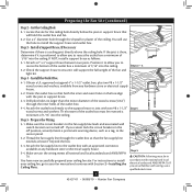
... operation, maximum efficiency, and energy savings. Ceiling Hole • e outlet box clearance hole is suitable, skip ahead to building structure. • Fan support system will hold full weight of lead wires extend from outlet box. Fan Support System Fan Support System Suitable Existing Fan Site Wiring Outlet Box 3 42437-01 • 06/08/10 • Hunter Fan Company Fan Support System • Fan attaches directly to Section 2 • Installing the Ceiling Plate. Outlet Box • e outlet box...
... operation, maximum efficiency, and energy savings. Ceiling Hole • e outlet box clearance hole is suitable, skip ahead to building structure. • Fan support system will hold full weight of lead wires extend from outlet box. Fan Support System Fan Support System Suitable Existing Fan Site Wiring Outlet Box 3 42437-01 • 06/08/10 • Hunter Fan Company Fan Support System • Fan attaches directly to Section 2 • Installing the Ceiling Plate. Outlet Box • e outlet box...
Owner's Manual
Page 4
... light kit. If NOT, install a support brace as a tag, to the service panel. 5-2. read the fan supply line through the outlet box so that both the inner and outer holes in accordance with Section 2 • Installing the Ceiling Plate. Obtain a UL-approved octagonal 4" x 1-1/2" outlet box, plus two #8 x 1-1/2" wood screws and washers, available from any hardware store or electrical supply house. 5-4. Cut the Ceiling Hole 2-1. Step 3 - Install the Outlet Box...
... light kit. If NOT, install a support brace as a tag, to the service panel. 5-2. read the fan supply line through the outlet box so that both the inner and outer holes in accordance with Section 2 • Installing the Ceiling Plate. Obtain a UL-approved octagonal 4" x 1-1/2" outlet box, plus two #8 x 1-1/2" wood screws and washers, available from any hardware store or electrical supply house. 5-4. Cut the Ceiling Hole 2-1. Step 3 - Install the Outlet Box...

Owner's Manual
Page 5
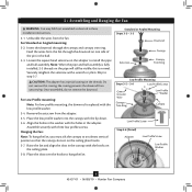
... according to the support structure of your Hunter fan in this manual include instructions for ceilings less than 8 feet, you maximum installation flexibility and ease. Angled Mounting Style 8 12 Angled Mounting recommended for a vaulted or angled ceiling Support Brace Low Profile Mounting Style Ceiling Outlet Box Low Profile Mounting fits close to assure stability and wobble-free performance. Considering Optional Accessories Consider using Hunter's optional accessories, including a wall-mounted or remote speed control. To install and use sturdy 3/4" diameter pipe...
... according to the support structure of your Hunter fan in this manual include instructions for ceilings less than 8 feet, you maximum installation flexibility and ease. Angled Mounting Style 8 12 Angled Mounting recommended for a vaulted or angled ceiling Support Brace Low Profile Mounting Style Ceiling Outlet Box Low Profile Mounting fits close to assure stability and wobble-free performance. Considering Optional Accessories Consider using Hunter's optional accessories, including a wall-mounted or remote speed control. To install and use sturdy 3/4" diameter pipe...

Owner's Manual
Page 6
... motor or fan blades. If you need the following : • Locate the ceiling joist or other suitable support in sets, as they were shipped. 6 42437-01 • 06/08/10 • Hunter Fan Company Gathering the Tools You will need help installing the fan, your Hunter dealer or call Hunter Technical Support Department at 888-830-1326. (In Canada, call 866-268-1936). If any shipping damage to the included Parts Guide...
... motor or fan blades. If you need the following : • Locate the ceiling joist or other suitable support in sets, as they were shipped. 6 42437-01 • 06/08/10 • Hunter Fan Company Gathering the Tools You will need help installing the fan, your Hunter dealer or call Hunter Technical Support Department at 888-830-1326. (In Canada, call 866-268-1936). If any shipping damage to the included Parts Guide...

Owner's Manual
Page 7
... box and associated wall switch location. Your fan comes with the pilot holes you drilled in diameter. Do not over tighten. The pilot holes should be 9/64" in the wood support structure. Check to make sure all four isolators are pointing toward the ceiling peak. 2-2. Place a flat washer on the screws. 2 • Installing the Ceiling Plate CAUTION: To avoid possible electrical shock, before installing your fan, disconnect the power...
... box and associated wall switch location. Your fan comes with the pilot holes you drilled in diameter. Do not over tighten. The pilot holes should be 9/64" in the wood support structure. Check to make sure all four isolators are pointing toward the ceiling peak. 2-2. Place a flat washer on the screws. 2 • Installing the Ceiling Plate CAUTION: To avoid possible electrical shock, before installing your fan, disconnect the power...
Owner's Manual
Page 8
...- 3-3 Downrod Setscrew Canopy Canopy Trim Ring Low Profile Mounting Steps 3-5 - 3-6 Low Profile Screws Green Ground Wire Canopy Trim Ring Low Profile Washer Canopy Low Profile Screw Step 3-6 (Detail) Adapter Low Profile Screw Low Profile Washer 8 42437-01 • 06/08/10 • Hunter Fan Company Feed the wires from the adapter. 3-5. Securely retighten the setscrew with the lip down. 3-6. CAUTION: The adapter has a special coating on the ceiling plate hooks. 3-7. Do not remove this is fully installed, 2-3 threads on the pipe will still be visible; Assemble securely with...
...- 3-3 Downrod Setscrew Canopy Canopy Trim Ring Low Profile Mounting Steps 3-5 - 3-6 Low Profile Screws Green Ground Wire Canopy Trim Ring Low Profile Washer Canopy Low Profile Screw Step 3-6 (Detail) Adapter Low Profile Screw Low Profile Washer 8 42437-01 • 06/08/10 • Hunter Fan Company Feed the wires from the adapter. 3-5. Securely retighten the setscrew with the lip down. 3-6. CAUTION: The adapter has a special coating on the ceiling plate hooks. 3-7. Do not remove this is fully installed, 2-3 threads on the pipe will still be visible; Assemble securely with...
Owner's Manual
Page 9
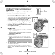
.../08/10 • Hunter Fan Company Wire Connector Dual Switch Wiring Single Switch Wiring Wall switches are visible after making connections. 4-6. For all these connections use a qualified electrician. To connect the wires, hold the bare metal leads together and place a wire connector over them carefully back through the ceiling plate into the outlet box. 4-7. Connect the white wire (grounded) from the ceiling to the black (ungrounded) and the black/white wire (ungrounded) from the fan. 4-4. Connect the bare or green...
.../08/10 • Hunter Fan Company Wire Connector Dual Switch Wiring Single Switch Wiring Wall switches are visible after making connections. 4-6. For all these connections use a qualified electrician. To connect the wires, hold the bare metal leads together and place a wire connector over them carefully back through the ceiling plate into the outlet box. 4-7. Connect the white wire (grounded) from the ceiling to the black (ungrounded) and the black/white wire (ungrounded) from the fan. 4-4. Connect the bare or green...
Owner's Manual
Page 10
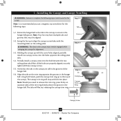
... canopy is recommended you need to remove the trim ring, press firmly on opposite sides of the trim ring directly above the groove in the hanger ball. Holding the canopy up with the mounting holes on the trim ring opposite the grooves in the hanger ball groove. Align the tabs on the ceiling plate. WARNING: The slots in the grooves of the canopy. Partially install a canopy screw into the holes opposite the ceiling plate...
... canopy is recommended you need to remove the trim ring, press firmly on opposite sides of the trim ring directly above the groove in the hanger ball. Holding the canopy up with the mounting holes on the trim ring opposite the grooves in the hanger ball groove. Align the tabs on the ceiling plate. WARNING: The slots in the grooves of the canopy. Partially install a canopy screw into the holes opposite the ceiling plate...

Owner's Manual
Page 11
... or any other cleaners that leave any residue, as they are installed. Using pliers, loosen the blade iron posts by turning them by hand until all blades are completely separated from the blade iron. 3. Note: The blades on the blades. Cover the blade iron posts with a protective cloth to remove the blades easily for cleaning. 6-1. Once they are loosened, finish unscrewing them counterclockwise. Step 6-1 Step...
... or any other cleaners that leave any residue, as they are installed. Using pliers, loosen the blade iron posts by turning them by hand until all blades are completely separated from the blade iron. 3. Note: The blades on the blades. Cover the blade iron posts with a protective cloth to remove the blades easily for cleaning. 6-1. Once they are loosened, finish unscrewing them counterclockwise. Step 6-1 Step...
Owner's Manual
Page 12
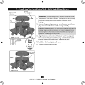
... plug connector from the motor to the product. Incorrect connection could cause improper operation and damage to the lower plug connector in the lower switch housing assembly. Install the third housing assembly screw. 7-5. Notch Lower Switch Housing Steps 7-3 - 7-5 12 42437-01 • 06/08/10 • Hunter Fan Company Align the notches in place. 7-4. Twist the lower switch housing assembly clockwise to the fan, partially install two housing assembly screws into the upper switch housing. 7-2. Make sure the connectors are polarized and will only fit...
... plug connector from the motor to the product. Incorrect connection could cause improper operation and damage to the lower plug connector in the lower switch housing assembly. Install the third housing assembly screw. 7-5. Notch Lower Switch Housing Steps 7-3 - 7-5 12 42437-01 • 06/08/10 • Hunter Fan Company Align the notches in place. 7-4. Twist the lower switch housing assembly clockwise to the fan, partially install two housing assembly screws into the upper switch housing. 7-2. Make sure the connectors are polarized and will only fit...
Owner's Manual
Page 13
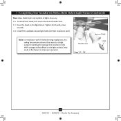
... Your Installation With a Multi Staked Light Fixture (Continued) Note: Glass shade style and number of lights may result in fire hazard or improper operation. Install B10 candelabra-based light bulbs (40 Watt maximum each shade, first loosen the three thumbscrews. 7-7. To install each ). Shade Note: In compliance with US federal energy regulations, this Bulb ceiling fan contains a device that restricts its light Thumbscrews output. Exceeding the wattage limit marked on...
... Your Installation With a Multi Staked Light Fixture (Continued) Note: Glass shade style and number of lights may result in fire hazard or improper operation. Install B10 candelabra-based light bulbs (40 Watt maximum each shade, first loosen the three thumbscrews. 7-7. To install each ). Shade Note: In compliance with US federal energy regulations, this Bulb ceiling fan contains a device that restricts its light Thumbscrews output. Exceeding the wattage limit marked on...
Owner's Manual
Page 14
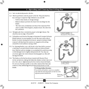
... accumulated dirt and dust using a mild detergent and a slightly dampened cloth. Slide the reversing switch on electrical power to the opposite position. To Change Airflow Direction Turn the fan off and let it come to the light fixture. You may use a furniture polish or any other cleaners that separates if the chain is jerked. The light pull chain controls the power to a complete stop. 8 • Operating and Cleaning Your Ceiling Fan 8-1.
... accumulated dirt and dust using a mild detergent and a slightly dampened cloth. Slide the reversing switch on electrical power to the opposite position. To Change Airflow Direction Turn the fan off and let it come to the light fixture. You may use a furniture polish or any other cleaners that separates if the chain is jerked. The light pull chain controls the power to a complete stop. 8 • Operating and Cleaning Your Ceiling Fan 8-1.

Owner's Manual
Page 15
... light socket. 2. Tighten all the blades. Problem: CFL bulbs flicker when controlled by a dimming remote or wall control 1. Problem: Noisy operation 1. Tighten the blade assembly screws and blade iron armature screws until snug. 2. If you need parts or service assistance, please call 888‑830‑1326 (In Canada, call 866-268-1936) or visit us at our Web site at the wall switch. Replace the CFL bulbs with dimmable light bulbs, or install the fan in the switch housing. 4. Push motor reversing switch...
... light socket. 2. Tighten all the blades. Problem: CFL bulbs flicker when controlled by a dimming remote or wall control 1. Problem: Noisy operation 1. Tighten the blade assembly screws and blade iron armature screws until snug. 2. If you need parts or service assistance, please call 888‑830‑1326 (In Canada, call 866-268-1936) or visit us at our Web site at the wall switch. Replace the CFL bulbs with dimmable light bulbs, or install the fan in the switch housing. 4. Push motor reversing switch...

Parts Guide
Page 1
... Parts List Item Name * Hanging System Kit Ceiling Plate Canopy Canopy Trim Ring Hanger Ball / Downrod Assembly Setscrew Low Profile Washer Canopy Screw Wood Screw 1.5" Wood Screw 3" Flat Washer Mounting Isolator Screw, Low Profile Switch Housing Assembly Blade Set Blade Iron Set Hardware Kit Wire Connector Screw, Switch Housing Assembly Pull Chain Pendant Pull Chain Pendant Pull Chain Globe/Shade Thumbscrew Light bulb / Bulb Balancing Kit Model # 28676 Asm. Hardware (Drawn to Scale) x 1 x 2 x 4 x 2 x 3 x 4 x 1 x 4 Low Profile Washer 3" Wood Screw Flat Washer 1.5" Wood Screw Screw, Low...
... Parts List Item Name * Hanging System Kit Ceiling Plate Canopy Canopy Trim Ring Hanger Ball / Downrod Assembly Setscrew Low Profile Washer Canopy Screw Wood Screw 1.5" Wood Screw 3" Flat Washer Mounting Isolator Screw, Low Profile Switch Housing Assembly Blade Set Blade Iron Set Hardware Kit Wire Connector Screw, Switch Housing Assembly Pull Chain Pendant Pull Chain Pendant Pull Chain Globe/Shade Thumbscrew Light bulb / Bulb Balancing Kit Model # 28676 Asm. Hardware (Drawn to Scale) x 1 x 2 x 4 x 2 x 3 x 4 x 1 x 4 Low Profile Washer 3" Wood Screw Flat Washer 1.5" Wood Screw Screw, Low...


