
Installation Guide
Page 1
...; Installing the Ceiling Plate. Ceiling Hole o e outlet box clearance hole is a ceiling joist directly above the floor and the ceiling is directly below a joist or support brace that the fan supply line extends at least 8 feet high. • e fan blades have now successfully prepared your fan manual and continue with 2 • Installing the Ceiling Plate. o e outer holes of the fan and light kit. Wiring o e electrical cable is acceptable and safe for safety, reliable operation, maximum...
...; Installing the Ceiling Plate. Ceiling Hole o e outlet box clearance hole is a ceiling joist directly above the floor and the ceiling is directly below a joist or support brace that the fan supply line extends at least 8 feet high. • e fan blades have now successfully prepared your fan manual and continue with 2 • Installing the Ceiling Plate. o e outer holes of the fan and light kit. Wiring o e electrical cable is acceptable and safe for safety, reliable operation, maximum...
Owner's Manual
Page 1
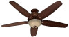
Model Name Model No. Date Purchased Where Purchased Type 2 Models Owner's Guide and Installation Manual English Español Form# 45068-01 200100519 ©2010 Hunter Fan Co. For Your Records and Warranty Assistance For reference, also attach your receipt or a copy of your receipt to the manual.
Model Name Model No. Date Purchased Where Purchased Type 2 Models Owner's Guide and Installation Manual English Español Form# 45068-01 200100519 ©2010 Hunter Fan Co. For Your Records and Warranty Assistance For reference, also attach your receipt or a copy of your receipt to the manual.
Owner's Manual
Page 2
.... If you complete instructions for Ceilings 9 Feet or Higher 8 4 •Wiring the Fan 9 5 • Installing the Canopy and Canopy Trim Ring 10 6 • Assembling the Blades 11 7 • Completing Your Installation With or Without a Bowl Light Fixture . . . . 12 8 • Operating and Cleaning Your Ceiling Fan 15 9 • Troubleshooting 16 Cautions and Warnings • READ THIS ENTIRE MANUAL CAREFULLY BEFORE BEGINNING INSTALLATION. Before installing your fan. Welcome Your new Hunter® ceiling fan is complete. © 2010 Hunter Fan Company 2 45068-01...
.... If you complete instructions for Ceilings 9 Feet or Higher 8 4 •Wiring the Fan 9 5 • Installing the Canopy and Canopy Trim Ring 10 6 • Assembling the Blades 11 7 • Completing Your Installation With or Without a Bowl Light Fixture . . . . 12 8 • Operating and Cleaning Your Ceiling Fan 15 9 • Troubleshooting 16 Cautions and Warnings • READ THIS ENTIRE MANUAL CAREFULLY BEFORE BEGINNING INSTALLATION. Before installing your fan. Welcome Your new Hunter® ceiling fan is complete. © 2010 Hunter Fan Company 2 45068-01...
Owner's Manual
Page 3
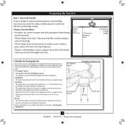
.... Fan Support System Fan Support System Suitable Existing Fan Site Wiring Outlet Box 3 45068-01 • 05/19/10 • Hunter Fan Company If your new Hunter fan. Choose the Fan Site Proper ceiling fan location and attachment to the building structure are at least 7 feet above the floor and the ceiling is at least 9 feet high. • e fan blades have no obstructions to airflow, such as walls or posts, within 30 inches...
.... Fan Support System Fan Support System Suitable Existing Fan Site Wiring Outlet Box 3 45068-01 • 05/19/10 • Hunter Fan Company If your new Hunter fan. Choose the Fan Site Proper ceiling fan location and attachment to the building structure are at least 7 feet above the floor and the ceiling is at least 9 feet high. • e fan blades have no obstructions to airflow, such as walls or posts, within 30 inches...
Owner's Manual
Page 4
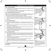
..., install a support brace as a tag, to allow you cannot lock the circuit breakers in accordance with wiring, use the hole to your ceiling fan site. Obtain a UL-approved octagonal 4" x 1-1/2" outlet box, plus two #8 x 1-1/2" wood screws and washers, available from any hardware store or electrical supply house. 5-4. Attach the outlet box directly to the support brace or joist with an approved connector, available at least 6" beyond the box...
..., install a support brace as a tag, to allow you cannot lock the circuit breakers in accordance with wiring, use the hole to your ceiling fan site. Obtain a UL-approved octagonal 4" x 1-1/2" outlet box, plus two #8 x 1-1/2" wood screws and washers, available from any hardware store or electrical supply house. 5-4. Attach the outlet box directly to the support brace or joist with an approved connector, available at least 6" beyond the box...
Owner's Manual
Page 5
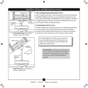
... Consider using Hunter's optional accessories, including a wall-mounted or remote speed control. Installer's Choice and Optional Accessories Support Brace Standard Mounting Style Ceiling Outlet Box Standard Mounting hangs from the ceiling by a downrod (included). Understanding Mounting and Installer's Choice® Hunter's patented 2-position mounting system provides you can install your Hunter fan in this manual include instructions for a vaulted or angled ceiling 5 45068-01 • 05/19/10 • Hunter Fan Company Support Brace Angled Mounting Style Ceiling Outlet Box 8 12...
... Consider using Hunter's optional accessories, including a wall-mounted or remote speed control. Installer's Choice and Optional Accessories Support Brace Standard Mounting Style Ceiling Outlet Box Standard Mounting hangs from the ceiling by a downrod (included). Understanding Mounting and Installer's Choice® Hunter's patented 2-position mounting system provides you can install your Hunter fan in this manual include instructions for a vaulted or angled ceiling 5 45068-01 • 05/19/10 • Hunter Fan Company Support Brace Angled Mounting Style Ceiling Outlet Box 8 12...
Owner's Manual
Page 6
... your Hunter dealer or call Hunter Technical Support Department at 888-830-1326 (In Canada, call 1-866-268-1936). Refer to the motor or fan blades. Proper ceiling fan location and attachment to the fan parts. If you begin installing the fan, follow all the instructions in sets, as they were shipped. 6 45068-01 • 05/19/10 • Hunter Fan Company If any shipping damage to the included Parts Guide. Installing Multiple Fans?
... your Hunter dealer or call Hunter Technical Support Department at 888-830-1326 (In Canada, call 1-866-268-1936). Refer to the motor or fan blades. Proper ceiling fan location and attachment to the fan parts. If you begin installing the fan, follow all the instructions in sets, as they were shipped. 6 45068-01 • 05/19/10 • Hunter Fan Company If any shipping damage to the included Parts Guide. Installing Multiple Fans?
Owner's Manual
Page 7
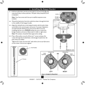
... over tighten. 3" Screw Flat Washer Ceiling Peak Large Opening OR Steps 2-2 - 2-4 Ceiling Peak Large Opening LEFT Step 2-3 (Angled Ceiling Only) 7 45068-01 • 05/19/10 • Hunter Fan Company RIGHT Align the slotted holes in Illustration 2-3 (left or right view). 2 • Installing the Hanger Bracket 2-1. The pilot holes should be sure to orient the hanger bracket as shown in the hanger bracket with four pre-installed neoprene noise isolators.
... over tighten. 3" Screw Flat Washer Ceiling Peak Large Opening OR Steps 2-2 - 2-4 Ceiling Peak Large Opening LEFT Step 2-3 (Angled Ceiling Only) 7 45068-01 • 05/19/10 • Hunter Fan Company RIGHT Align the slotted holes in Illustration 2-3 (left or right view). 2 • Installing the Hanger Bracket 2-1. The pilot holes should be sure to orient the hanger bracket as shown in the hanger bracket with four pre-installed neoprene noise isolators.
Owner's Manual
Page 8
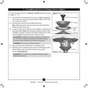
... pop into the hanger bracket. 3-5. WARNING: Do not carry or lift fan by canopy. 3-4. Note: Make sure all the wires are on the pipe will still be visible; Once assembled, do not remove the downrod. 3 • Assembling the Fan for Ceilings 9 Feet or Higher You can assemble your fan for standard or angled mounting as directed in these installation instructions. To assemble fan to 4 • Wiring the Fan. Loosen the square...
... pop into the hanger bracket. 3-5. WARNING: Do not carry or lift fan by canopy. 3-4. Note: Make sure all the wires are on the pipe will still be visible; Once assembled, do not remove the downrod. 3 • Assembling the Fan for Ceilings 9 Feet or Higher You can assemble your fan for standard or angled mounting as directed in these installation instructions. To assemble fan to 4 • Wiring the Fan. Loosen the square...
Owner's Manual
Page 9
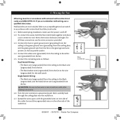
... outlet box. Wall switches are unfamiliar with wiring, use the wire connectors provided. 4-3. For all these connections use a qualified electrician. Connect the bare or green ground wire (grounding) from the ceiling to the green ground wire (grounding) from the ceiling plate and the green ground wire from the fan. 4-5. Wire Connector 9 45068-01 • 05/19/10 • Hunter Fan Company Before attempting installation, make sure the power is still off. 4-2. Connect the white wire (grounded...
... outlet box. Wall switches are unfamiliar with wiring, use the wire connectors provided. 4-3. For all these connections use a qualified electrician. Connect the bare or green ground wire (grounding) from the ceiling to the green ground wire (grounding) from the ceiling plate and the green ground wire from the fan. 4-5. Wire Connector 9 45068-01 • 05/19/10 • Hunter Fan Company Before attempting installation, make sure the power is still off. 4-2. Connect the white wire (grounded...

Owner's Manual
Page 10
...Twist canopy trim ring clockwise to remove the canopy trim ring, follow these steps: 1. 5 • Installing the Canopy and Canopy Trim Ring 5-1. Steps 5-1 - 5-2 Canopy Should you need to secure the canopy. Securely tighten all four screws. 5-5. Raise the canopy over the hanger bracket. Hanger Bracket Canopy Trim Ring Step 5-4 Step 5-3 Step 5-5 Canopy Screw 10 45068-01 • 05/19/10 • Hunter Fan Company Partially install two canopy screws (about 2 full turns) in round hole on canopy. Install third & fourth canopy screw in the hanger bracket. 5-2. Using both...
...Twist canopy trim ring clockwise to remove the canopy trim ring, follow these steps: 1. 5 • Installing the Canopy and Canopy Trim Ring 5-1. Steps 5-1 - 5-2 Canopy Should you need to secure the canopy. Securely tighten all four screws. 5-5. Raise the canopy over the hanger bracket. Hanger Bracket Canopy Trim Ring Step 5-4 Step 5-3 Step 5-5 Canopy Screw 10 45068-01 • 05/19/10 • Hunter Fan Company Partially install two canopy screws (about 2 full turns) in round hole on canopy. Install third & fourth canopy screw in the hanger bracket. 5-2. Using both...
Owner's Manual
Page 11
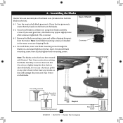
... the blade iron, and attach lightly to a blade iron using three blade assembly screws. This is normal. 6-3. 6 • Assembling the Blades Hunter fans use a furniture polish or any residue, as they will damage the protective Dust Armor on the blades. If you used grommets, the blades may include blade grommets. Do not use several styles of fan blade irons (brackets that leave any other cleaners that hold the blade to secure shipping blocks. 6-4. Remove the blade mounting screws and rubber shipping bumpers from the motor...
... the blade iron, and attach lightly to a blade iron using three blade assembly screws. This is normal. 6-3. 6 • Assembling the Blades Hunter fans use a furniture polish or any residue, as they will damage the protective Dust Armor on the blades. If you used grommets, the blades may include blade grommets. Do not use several styles of fan blade irons (brackets that leave any other cleaners that hold the blade to secure shipping blocks. 6-4. Remove the blade mounting screws and rubber shipping bumpers from the motor...
Owner's Manual
Page 12
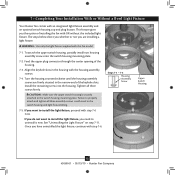
... securely attached to install the light fixture, proceed with an integrated light fixture assembly and an optional switch housing cap and plug button. The steps below direct you whether or not you want to install the light fixture, you need to properly attach and tighten all three screws firmly. If you do not want to the switch housing mounting plate. Steps 7-1 - 7-3 Housing Assembly Screw Upper Switch Housing 12 45068-01 • 05/19/10 • Hunter Fan Company
... securely attached to install the light fixture, proceed with an integrated light fixture assembly and an optional switch housing cap and plug button. The steps below direct you whether or not you want to install the light fixture, you need to properly attach and tighten all three screws firmly. If you do not want to the switch housing mounting plate. Steps 7-1 - 7-3 Housing Assembly Screw Upper Switch Housing 12 45068-01 • 05/19/10 • Hunter Fan Company
Owner's Manual
Page 13
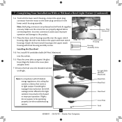
... be operating properly, see the troubleshooting section. Attach the lower switch housing to the light socket(s) may result in the cover plate and glass bowl. 7-10.S crew the finial onto the threaded rod end until tight. Steps 7-6 - 7-7 Plug Connector Lower Switch Housing Housing Assembly Screw for Light Bulbs (60 Watt Maximum) Note: In compliance with three housing assembly screws. Metal Disk Metal Rod Glass Bowl Cover Plate Finial 13 45068-01 • 05/19/10 • Hunter Fan Company Installing the Glass Bowl 7-8. Place the cover plate...
... be operating properly, see the troubleshooting section. Attach the lower switch housing to the light socket(s) may result in the cover plate and glass bowl. 7-10.S crew the finial onto the threaded rod end until tight. Steps 7-6 - 7-7 Plug Connector Lower Switch Housing Housing Assembly Screw for Light Bulbs (60 Watt Maximum) Note: In compliance with three housing assembly screws. Metal Disk Metal Rod Glass Bowl Cover Plate Finial 13 45068-01 • 05/19/10 • Hunter Fan Company Installing the Glass Bowl 7-8. Place the cover plate...
Owner's Manual
Page 14
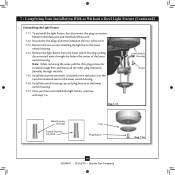
... Light Fixture 7-11. To uninstall the light fixture, first disconnect the plug connectors between the two white wires. 7-13. Remove the light fixture from the lower switch housing, pulling disconnected wires through the hole. 7-15. Install the switch housing cap and plug button to the lower switch housing. 7-14. Lower Switch Housing Screw Step 7-13 Male Dummy Terminal Female Dummy Terminal Cap Plug Button Step 7-16 14 45068-01 • 05/19/10 • Hunter Fan Company Remove the two screws attaching the light kit to the lower switch housing...
... Light Fixture 7-11. To uninstall the light fixture, first disconnect the plug connectors between the two white wires. 7-13. Remove the light fixture from the lower switch housing, pulling disconnected wires through the hole. 7-15. Install the switch housing cap and plug button to the lower switch housing. 7-14. Lower Switch Housing Screw Step 7-13 Male Dummy Terminal Female Dummy Terminal Cap Plug Button Step 7-16 14 45068-01 • 05/19/10 • Hunter Fan Company Remove the two screws attaching the light kit to the lower switch housing...
Owner's Manual
Page 15
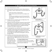
... fan pull chain controls power to clean the blades. The chain has two settings: ON and OFF. Ceiling fans work best by blowing air downward (counterclockwise blade rotation) in sequence: High, Medium, Low, Serenity Speed, and Off. • Pull the chain slowly to change settings. • Release slowly to prevent the chain from recoiling into the connector. 8-3. Remove surface smudges or accumulated dirt and dust using a mild detergent and a slightly dampened cloth. Restart fan. Dust Armor on electrical power...
... fan pull chain controls power to clean the blades. The chain has two settings: ON and OFF. Ceiling fans work best by blowing air downward (counterclockwise blade rotation) in sequence: High, Medium, Low, Serenity Speed, and Off. • Pull the chain slowly to change settings. • Release slowly to prevent the chain from recoiling into the connector. 8-3. Remove surface smudges or accumulated dirt and dust using a mild detergent and a slightly dampened cloth. Restart fan. Dust Armor on electrical power...
Owner's Manual
Page 16
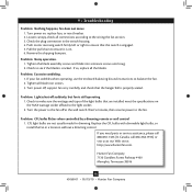
... wall control 1. CFL light bulbs are installed meet the specifications on the MAX wattage sticker affixed to ensure that the switch is cracked. 9 • Troubleshooting Problem: Nothing happens; Push motor reversing switch firmly left or right to the light socket. 2. Check to ensure it is properly seated. fan does not move. 1. Pull the pull chain to see if the blade is engaged. 5. Remove the shipping bumpers. Check to the fan. Tighten the blade assembly screws and blade iron armature screws...
... wall control 1. CFL light bulbs are installed meet the specifications on the MAX wattage sticker affixed to ensure that the switch is cracked. 9 • Troubleshooting Problem: Nothing happens; Push motor reversing switch firmly left or right to the light socket. 2. Check to ensure it is properly seated. fan does not move. 1. Pull the pull chain to see if the blade is engaged. 5. Remove the shipping bumpers. Check to the fan. Tighten the blade assembly screws and blade iron armature screws...

Parts Guide
Page 1
... included in the box. REFER TO THE INSTALLATION MANUAL FOR FULL ASSEMBLY INSTRUCTIONS. Model # 28672 Parts List Asm. Dwg. # 99920-01 Item Name * Hanging System Kit Hanger Ball / Downrod Assembly Ceiling Plate Finish Qnty 1 1 Northern Sienna Part # 98026-93 87942-03 Canopy Canopy Trim Ring Canopy Screw Wood Screw 1.5" Wood Screw 3" Flat Washer Mounting Isolator Switch Housing Assembly Switch Housing Cover Switch Housing Plug Button Light Kit Assembly Blade Iron Set Blade Set Screw, Blade Iron Armature Hardware Kit Blade Grommet Blade Assembly Screw 1 99919-93 1 73853...
... included in the box. REFER TO THE INSTALLATION MANUAL FOR FULL ASSEMBLY INSTRUCTIONS. Model # 28672 Parts List Asm. Dwg. # 99920-01 Item Name * Hanging System Kit Hanger Ball / Downrod Assembly Ceiling Plate Finish Qnty 1 1 Northern Sienna Part # 98026-93 87942-03 Canopy Canopy Trim Ring Canopy Screw Wood Screw 1.5" Wood Screw 3" Flat Washer Mounting Isolator Switch Housing Assembly Switch Housing Cover Switch Housing Plug Button Light Kit Assembly Blade Iron Set Blade Set Screw, Blade Iron Armature Hardware Kit Blade Grommet Blade Assembly Screw 1 99919-93 1 73853...


