
Installation Guide
Page 1
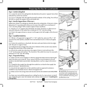
... support the full weight of the fan and light kit. Locate the site for your fan manual and continue with 2 • Installing the Ceiling Plate. Step 4 Step 4 Install the Outlet Box 4-1. If you cannot lock the circuit breakers in the box align with national and local electrical codes and ANSI/NFPA 70. For instructions to install your ceiling fan, go to your ceiling fan site. Preparing the Fan Site 8' Minimum Ceiling Height 7' Minimum to Floor...
... support the full weight of the fan and light kit. Locate the site for your fan manual and continue with 2 • Installing the Ceiling Plate. Step 4 Step 4 Install the Outlet Box 4-1. If you cannot lock the circuit breakers in the box align with national and local electrical codes and ANSI/NFPA 70. For instructions to install your ceiling fan, go to your ceiling fan site. Preparing the Fan Site 8' Minimum Ceiling Height 7' Minimum to Floor...
Parts Guide
Page 1
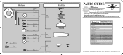
.... REFER TO THE INSTALLATION MANUAL FOR FULL ASSEMBLY INSTRUCTIONS. Parts List Item Name * Hanging System Kit Ceiling Plate Canopy Canopy Trim Ring Hanger Ball / Downrod Assembly Low Profile Washer Canopy Screw Wood Screw Flat Washer Mounting Isolator * Locking Screw Machine Screw 8-32 Blade Set Screw, Blade Iron Armature Switch Housing Cover Bottom Cap Hardware Kit Blade Assembly Screw Screw, Machine, 6-32 Wire Connector Screw, Switch Housing Assembly Balancing Kit Model # Asm. Dwg. # Finish Qnty 1 25866 93738-04 Gloss White Part # 94945-03 25867 93738-06 Brushed Nickel Part # 94945-09...
.... REFER TO THE INSTALLATION MANUAL FOR FULL ASSEMBLY INSTRUCTIONS. Parts List Item Name * Hanging System Kit Ceiling Plate Canopy Canopy Trim Ring Hanger Ball / Downrod Assembly Low Profile Washer Canopy Screw Wood Screw Flat Washer Mounting Isolator * Locking Screw Machine Screw 8-32 Blade Set Screw, Blade Iron Armature Switch Housing Cover Bottom Cap Hardware Kit Blade Assembly Screw Screw, Machine, 6-32 Wire Connector Screw, Switch Housing Assembly Balancing Kit Model # Asm. Dwg. # Finish Qnty 1 25866 93738-04 Gloss White Part # 94945-03 25867 93738-06 Brushed Nickel Part # 94945-09...

Owner's Manual
Page 1
Date Purchased Where Purchased Type T Models Owner's Guide and Installation Manual English Español Form# 42774-01 20090612 ©2009 Hunter Fan Co. For Your Records and Warranty Assistance For reference, also attach your receipt or a copy of your receipt to the manual. Model Name Model No.
Date Purchased Where Purchased Type T Models Owner's Guide and Installation Manual English Español Form# 42774-01 20090612 ©2009 Hunter Fan Co. For Your Records and Warranty Assistance For reference, also attach your receipt or a copy of your receipt to the manual. Model Name Model No.
Owner's Manual
Page 2
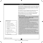
... electrical codes and ANSI/NFPA 70. Table Of Contents 1 • Getting Ready 6 2 • Installing the Ceiling Plate 7 3 • Assembling the Top Housing 8 4 • Assembling and Hanging the Fan . . . 9 5 • Wiring the Fan 10 6 • Installing the Canopy and Canopy Trim Ring 11 7 • Assembling the Blades 12 8 • Installing the Switch Housing 13 9 • Operating and Cleaning Your Ceiling Fan 14 10 • Troubleshooting 15 Welcome Your new Hunter® ceiling fan is an addition to the outlet box and associated wall switch location. Before installing...
... electrical codes and ANSI/NFPA 70. Table Of Contents 1 • Getting Ready 6 2 • Installing the Ceiling Plate 7 3 • Assembling the Top Housing 8 4 • Assembling and Hanging the Fan . . . 9 5 • Wiring the Fan 10 6 • Installing the Canopy and Canopy Trim Ring 11 7 • Assembling the Blades 12 8 • Installing the Switch Housing 13 9 • Operating and Cleaning Your Ceiling Fan 14 10 • Troubleshooting 15 Welcome Your new Hunter® ceiling fan is an addition to the outlet box and associated wall switch location. Before installing...
Owner's Manual
Page 3
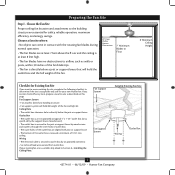
... Fan Site Wiring Outlet Box 3 42774-01 • 06/12/09 • Hunter Fan Company Fan Support System • Fan attaches directly to Floor 8' Minimum Ceiling Height Checklist for Existing Fan Site If you cannot check off every item, prepare a new fan site as walls or posts, within 30 inches of the fan blade tips. • e fan is suitable, skip ahead to the joist or support brace by an approved connector...
... Fan Site Wiring Outlet Box 3 42774-01 • 06/12/09 • Hunter Fan Company Fan Support System • Fan attaches directly to Floor 8' Minimum Ceiling Height Checklist for Existing Fan Site If you cannot check off every item, prepare a new fan site as walls or posts, within 30 inches of the fan blade tips. • e fan is suitable, skip ahead to the joist or support brace by an approved connector...
Owner's Manual
Page 4
... and associated wall switch location are unfamiliar with wiring, use the hole to install the support brace and outlet box. Obtain a UL-approved octagonal 4" x 1-1/2" outlet box, plus two #8 x 1-1/2" wood screws and washers, available from any hardware store or electrical supply house. 5-4. Make certain the wiring meets all national and local standards and ANSI/NFPA 70. Cut a 4" diameter hole through the inner holes of 1/16" into the ceiling. 3-2. Install a Support Brace...
... and associated wall switch location are unfamiliar with wiring, use the hole to install the support brace and outlet box. Obtain a UL-approved octagonal 4" x 1-1/2" outlet box, plus two #8 x 1-1/2" wood screws and washers, available from any hardware store or electrical supply house. 5-4. Make certain the wiring meets all national and local standards and ANSI/NFPA 70. Cut a 4" diameter hole through the inner holes of 1/16" into the ceiling. 3-2. Install a Support Brace...
Owner's Manual
Page 5
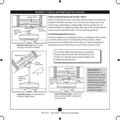
... high CAUTION: To reduce the risk of personal injury, attach the fan directly to the support structure of your Hunter fan in this manual include instructions for ceilings less than 8 feet, you maximum installation flexibility and ease. Angled Mounting Style 8 12 Angled Mounting recommended for a vaulted or angled ceiling Support Brace Low Profile Mounting Style Ceiling Outlet Box Low Profile Mounting fits close to the ceiling, recommended for all three Installer's Choice mounting methods. You can purchase Hunter extension downrods. Installer...
... high CAUTION: To reduce the risk of personal injury, attach the fan directly to the support structure of your Hunter fan in this manual include instructions for ceilings less than 8 feet, you maximum installation flexibility and ease. Angled Mounting Style 8 12 Angled Mounting recommended for a vaulted or angled ceiling Support Brace Low Profile Mounting Style Ceiling Outlet Box Low Profile Mounting fits close to the ceiling, recommended for all three Installer's Choice mounting methods. You can purchase Hunter extension downrods. Installer...
Owner's Manual
Page 6
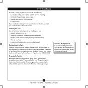
... you begin installing the fan, follow all the instructions in ceiling. • Drill holes for safety, reliable operation, maximum efficiency, and energy savings. Refer to the included Parts Guide. If any shipping damage to the motor or fan blades. If you are missing or damaged, contact your Hunter dealer or call Hunter Technical Support Department at 888-830-1326. Installing Multiple Fans? Check for installing the fan: • Electric drill...
... you begin installing the fan, follow all the instructions in ceiling. • Drill holes for safety, reliable operation, maximum efficiency, and energy savings. Refer to the included Parts Guide. If any shipping damage to the motor or fan blades. If you are missing or damaged, contact your Hunter dealer or call Hunter Technical Support Department at 888-830-1326. Installing Multiple Fans? Check for installing the fan: • Electric drill...
Owner's Manual
Page 7
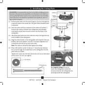
... ceiling plate. 2-3. Position the isolators between the ceiling plate and ceiling by turning off position, securely fasten a prominent warning device, such as a tag, to the service panel. 2-1. Note: The isolators should be flush against the ceiling. 2-5. Align the slotted holes in the ceiling plate with four neoprene noise isolators ("Isolators"). Isolator Ceiling Plate Flat Washer Step 2-2 Steps 2-3 - 2-5 3" Wood Screw For Angled Ceilings: Be sure to the outlet box and associated wall switch location. The pilot holes...
... ceiling plate. 2-3. Position the isolators between the ceiling plate and ceiling by turning off position, securely fasten a prominent warning device, such as a tag, to the service panel. 2-1. Note: The isolators should be flush against the ceiling. 2-5. Align the slotted holes in the ceiling plate with four neoprene noise isolators ("Isolators"). Isolator Ceiling Plate Flat Washer Step 2-2 Steps 2-3 - 2-5 3" Wood Screw For Angled Ceilings: Be sure to the outlet box and associated wall switch location. The pilot holes...
Owner's Manual
Page 8
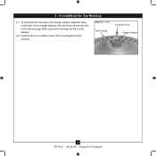
Install three (3) assembly screws (#8-32) and tighten them securely. Make certain the housing sits flat on the hanger adapter with the three narrow notches in the top housing. Steps 3-1 - 3-2 Top Housing Assembly Screw Hanger Adapter 8 42774-01 • 06/12/09 • Hunter Fan Company To assemble the housing to the hanger adapter, align the three raised tabs on the adapter. 3-2. 3 • Assembling the Top Housing 3-1.
Install three (3) assembly screws (#8-32) and tighten them securely. Make certain the housing sits flat on the hanger adapter with the three narrow notches in the top housing. Steps 3-1 - 3-2 Top Housing Assembly Screw Hanger Adapter 8 42774-01 • 06/12/09 • Hunter Fan Company To assemble the housing to the hanger adapter, align the three raised tabs on the adapter. 3-2. 3 • Assembling the Top Housing 3-1.
Owner's Manual
Page 9
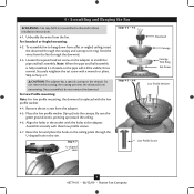
... washer with three low profile screws. 4-7. Step 4-7 U-shaped Hole Steps 4-2 - 4-3 Downrod Canopy Canopy Trim Ring Set Screw Steps 4-5 - 4-6 Low Profile Washer Low Profile Screw 9 42774-01 • 06/12/09 • Hunter Fan Company For Standard or Angled mounting: 4-2. Note: When the pipe and ball assembly is replaced with a wrench or pliers. the coating prevents the downrod from the adapter. 4-5. To assemble fan to hang down from the fan through the downrod. 4-3. Once assembled, do not remove the downrod. Be sure the green ground wire...
... washer with three low profile screws. 4-7. Step 4-7 U-shaped Hole Steps 4-2 - 4-3 Downrod Canopy Canopy Trim Ring Set Screw Steps 4-5 - 4-6 Low Profile Washer Low Profile Screw 9 42774-01 • 06/12/09 • Hunter Fan Company For Standard or Angled mounting: 4-2. Note: When the pipe and ball assembly is replaced with a wrench or pliers. the coating prevents the downrod from the adapter. 4-5. To assemble fan to hang down from the fan through the downrod. 4-3. Once assembled, do not remove the downrod. Be sure the green ground wire...
Owner's Manual
Page 10
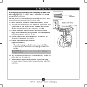
... connections use a qualified electrician. Connect the remaining wires as follows: Single Switch Wiring: • The black wire (ungrounded) from the ceiling to the black (ungrounded) and the black/white wire (ungrounded) from the fan. 5-4. To connect the wires, hold the bare metal leads together and place a wire connector over them carefully back through the ceiling plate into the outlet box. 5-7. Select an acceptable general-use switch in accordance with national and local electrical codes...
... connections use a qualified electrician. Connect the remaining wires as follows: Single Switch Wiring: • The black wire (ungrounded) from the ceiling to the black (ungrounded) and the black/white wire (ungrounded) from the fan. 5-4. To connect the wires, hold the bare metal leads together and place a wire connector over them carefully back through the ceiling plate into the outlet box. 5-7. Select an acceptable general-use switch in accordance with national and local electrical codes...
Owner's Manual
Page 11
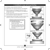
... bumps on opposite sides of tabs. 2. Steps 6-4 - 6-5 Ceiling Plate Canopy Trim Ring Step 6-3 Canopy Screw 11 42774-01 • 06/12/09 • Hunter Fan Company The canopy trim ring will flex out releasing the trim ring from the canopy. Press firmly on top of the ring toward the canopy. 6 • Installing the Canopy and Canopy Trim Ring 6-1. Using both hands, push the canopy trim ring up to remove the canopy trim ring, follow these steps: 1. The tabs will snap and...
... bumps on opposite sides of tabs. 2. Steps 6-4 - 6-5 Ceiling Plate Canopy Trim Ring Step 6-3 Canopy Screw 11 42774-01 • 06/12/09 • Hunter Fan Company The canopy trim ring will flex out releasing the trim ring from the canopy. Press firmly on top of the ring toward the canopy. 6 • Installing the Canopy and Canopy Trim Ring 6-1. Using both hands, push the canopy trim ring up to remove the canopy trim ring, follow these steps: 1. The tabs will snap and...
Owner's Manual
Page 12
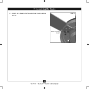
Step 7-1 Blade Assembly Screw 12 42774-01 • 06/12/09 • Hunter Fan Company 7 • Assembling the Blades 7-1. Attach each blade to the fan using three blade assembly screws.
Step 7-1 Blade Assembly Screw 12 42774-01 • 06/12/09 • Hunter Fan Company 7 • Assembling the Blades 7-1. Attach each blade to the fan using three blade assembly screws.
Owner's Manual
Page 13
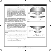
... the switch housing. Switch Housing Cover 8-3. Pull Chain Screw Switch Housing Cap 13 42774-01 • 06/12/09 • Hunter Fan Company Bottom Cover Step 8-1 8-2. Insert the chain into its final position. Make sure you do not trap any electrical wires between the two parts. Assemble the bottom cover by attaching the small round cover to the large round hole in the cover with the (2) threaded holes closest to the bottom of the switch housing. Reversing Switch NOTE...
... the switch housing. Switch Housing Cover 8-3. Pull Chain Screw Switch Housing Cap 13 42774-01 • 06/12/09 • Hunter Fan Company Bottom Cover Step 8-1 8-2. Insert the chain into its final position. Make sure you do not trap any electrical wires between the two parts. Assemble the bottom cover by attaching the small round cover to the large round hole in the cover with the (2) threaded holes closest to the bottom of the switch housing. Reversing Switch NOTE...
Owner's Manual
Page 14
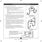
... the room without causing a draft. 9-4. Slide the reversing switch on electrical power to a complete stop. The fan pull chain controls power to the opposite position. The pull chain has four settings in warm weather to prevent the chain from recoiling into the connector. 9-3. Ceiling fans work best by blowing air downward (counterclockwise blade rotation) in sequence: High, Medium, Low and Off. • Pull the chain slowly to change settings. • Release slowly to cool the room...
... the room without causing a draft. 9-4. Slide the reversing switch on electrical power to a complete stop. The fan pull chain controls power to the opposite position. The pull chain has four settings in warm weather to prevent the chain from recoiling into the connector. 9-3. Ceiling fans work best by blowing air downward (counterclockwise blade rotation) in sequence: High, Medium, Low and Off. • Pull the chain slowly to change settings. • Release slowly to cool the room...
Owner's Manual
Page 15
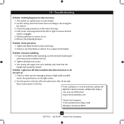
... on , replace fuse, or reset breaker. 2. Check to the fan. If so, replace all blade iron screws. 3. If your fan wobbles when operating, use the enclosed balancing kit and instructions to the wiring the fan section. 3. Push motor reversing switch firmly left or right to see if the blade is engaged. 5. Problem: Excessive wobbling. 1. Remove the shipping bumpers. Loosen canopy, check all connections according to balance the fan. 2. fan does not move. 1. If you need parts or service assistance...
... on , replace fuse, or reset breaker. 2. Check to the fan. If so, replace all blade iron screws. 3. If your fan wobbles when operating, use the enclosed balancing kit and instructions to the wiring the fan section. 3. Push motor reversing switch firmly left or right to see if the blade is engaged. 5. Problem: Excessive wobbling. 1. Remove the shipping bumpers. Loosen canopy, check all connections according to balance the fan. 2. fan does not move. 1. If you need parts or service assistance...


