
Installation Guide
Page 1
...octagonal 4" x 1-1/2" outlet box • Two #8 x 1-1/2" wood screws and washers • Approved connector for electrical wire Checklist for your new Hunter fan. If you cannot lock the circuit breakers in accordance with two #8 x 1-1/2" wood screws and washers. e bottom of the outlet box ...qualified electrician. 41681-01 • 02/20/04 Fan Support System o Fan attaches directly to outlet box by the support brace manufacturer). Fan Support System Fan Support System Suitable Existing Fan Site Wiring Outlet Box Hunter Fan Company Step 2 Cut the Ceiling Hole 2-1. If ...
...octagonal 4" x 1-1/2" outlet box • Two #8 x 1-1/2" wood screws and washers • Approved connector for electrical wire Checklist for your new Hunter fan. If you cannot lock the circuit breakers in accordance with two #8 x 1-1/2" wood screws and washers. e bottom of the outlet box ...qualified electrician. 41681-01 • 02/20/04 Fan Support System o Fan attaches directly to outlet box by the support brace manufacturer). Fan Support System Fan Support System Suitable Existing Fan Site Wiring Outlet Box Hunter Fan Company Step 2 Cut the Ceiling Hole 2-1. If ...
Parts Guide
Page 1
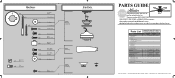
...GUIDE IS FOR REFERENCE ONLY. Dwg. # Finish Qnty 1 25866 93738-04 Gloss White Part # 94945-03 25867 93738-06 Brushed Nickel Part # 94945-09 6 74508-36 74508-36 1 G0677-13 G0677-45 11 ...-01 84007-01 1 96757-01 96757-01 1 93738-00-863 93738-05-865 1 07570-01 07570-01 Hunter Fan Company • 7130 Goodlett Farms Pkwy. #400 • Memphis, TN 38016 • www.hunterfan.com ..., Blade Assembly Flat Washer Screw, Machine, 6-32 Hanger Bracket Assembly Blade Assembly Switch Housing Assembly Fan Parts (Not Drawn to Scale) PARTS GUIDE Using this Parts Guide, make sure all parts are...
...GUIDE IS FOR REFERENCE ONLY. Dwg. # Finish Qnty 1 25866 93738-04 Gloss White Part # 94945-03 25867 93738-06 Brushed Nickel Part # 94945-09 6 74508-36 74508-36 1 G0677-13 G0677-45 11 ...-01 84007-01 1 96757-01 96757-01 1 93738-00-863 93738-05-865 1 07570-01 07570-01 Hunter Fan Company • 7130 Goodlett Farms Pkwy. #400 • Memphis, TN 38016 • www.hunterfan.com ..., Blade Assembly Flat Washer Screw, Machine, 6-32 Hanger Bracket Assembly Blade Assembly Switch Housing Assembly Fan Parts (Not Drawn to Scale) PARTS GUIDE Using this Parts Guide, make sure all parts are...

Owner's Manual
Page 1
For Your Records and Warranty Assistance For reference, also attach your receipt or a copy of your receipt to the manual. Date Purchased Where Purchased Type T Models Owner's Guide and Installation Manual English Español Form# 42774-01 20090612 ©2009 Hunter Fan Co. Model Name Model No.
For Your Records and Warranty Assistance For reference, also attach your receipt or a copy of your receipt to the manual. Date Purchased Where Purchased Type T Models Owner's Guide and Installation Manual English Español Form# 42774-01 20090612 ©2009 Hunter Fan Co. Model Name Model No.
Owner's Manual
Page 2
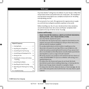
... the Blades 12 8 • Installing the Switch Housing 13 9 • Operating and Cleaning Your Ceiling Fan 14 10 • Troubleshooting 15 Welcome Your new Hunter® ceiling fan is an addition to your fan, disconnect the power by turning off position, securely fasten a prominent warning device, such as a tag, ... • All wiring must be in the world. SAVE THESE INSTRUCTIONS. • Use only Hunter replacement parts. • To reduce the risk of personal injury, attach the fan directly to supply you cannot lock the circuit breakers in the off the circuit breakers to the ...
... the Blades 12 8 • Installing the Switch Housing 13 9 • Operating and Cleaning Your Ceiling Fan 14 10 • Troubleshooting 15 Welcome Your new Hunter® ceiling fan is an addition to your fan, disconnect the power by turning off position, securely fasten a prominent warning device, such as a tag, ... • All wiring must be in the world. SAVE THESE INSTRUCTIONS. • Use only Hunter replacement parts. • To reduce the risk of personal injury, attach the fan directly to supply you cannot lock the circuit breakers in the off the circuit breakers to the ...
Owner's Manual
Page 3
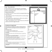
... page. Outlet Box • e outlet box is recessed a minimum of the fan and light kit. If your new Hunter fan. If you cannot check off every item, prepare a new fan site as specifi ed by the support brace manufacturer). • e outlet box is...;e outlet box clearance hole is directly below the joist or support brace. Fan Support System Fan Support System Suitable Existing Fan Site Wiring Outlet Box 3 42774-01 • 06/12/09 • Hunter Fan Company Fan Support System • Fan attaches directly to Section 2 • Installing the Ceiling Plate.
... page. Outlet Box • e outlet box is recessed a minimum of the fan and light kit. If your new Hunter fan. If you cannot check off every item, prepare a new fan site as specifi ed by the support brace manufacturer). • e outlet box is...;e outlet box clearance hole is directly below the joist or support brace. Fan Support System Fan Support System Suitable Existing Fan Site Wiring Outlet Box 3 42774-01 • 06/12/09 • Hunter Fan Company Fan Support System • Fan attaches directly to Section 2 • Installing the Ceiling Plate.
Owner's Manual
Page 4
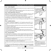
...(continued) Step 2 - You will use a qualified electrician. 42774-01 • 06/12/09 • Hunter Fan Company If the joist is there, determine if it will hold the outlet box and fan. 2-2. Obtain a UL-approved octagonal 4" x 1-1/2" outlet box, plus two #8 x 1-1/2" wood screws and ...turned off position, securely fasten a prominent warning device, such as follows: 3-1. Step 5 - For instructions to install your ceiling fan, go to the fan supply line leads and associated wall switch location are unfamiliar with an approved connector, available at least 6" beyond the box. 5-3. Cut...
...(continued) Step 2 - You will use a qualified electrician. 42774-01 • 06/12/09 • Hunter Fan Company If the joist is there, determine if it will hold the outlet box and fan. 2-2. Obtain a UL-approved octagonal 4" x 1-1/2" outlet box, plus two #8 x 1-1/2" wood screws and ...turned off position, securely fasten a prominent warning device, such as follows: 3-1. Step 5 - For instructions to install your ceiling fan, go to the fan supply line leads and associated wall switch location are unfamiliar with an approved connector, available at least 6" beyond the box. 5-3. Cut...
Owner's Manual
Page 5
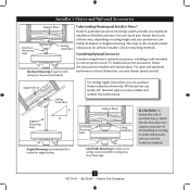
... including a wall-mounted or remote speed control. For quiet and optimum performance of three ways, depending on ceiling height and your Hunter fan, use sturdy 3/4" diameter pipe to the ceiling, recommended for all three Installer's Choice mounting methods. To install and use only... the hardware supplied. 5 42774-01 • 06/12/09 • Hunter Fan Company Installer's Choice and Optional Accessories Support Brace Standard Mounting Style Ceiling Outlet Box Standard Mounting hangs from the ceiling by a downrod (...
... including a wall-mounted or remote speed control. For quiet and optimum performance of three ways, depending on ceiling height and your Hunter fan, use sturdy 3/4" diameter pipe to the ceiling, recommended for all three Installer's Choice mounting methods. To install and use only... the hardware supplied. 5 42774-01 • 06/12/09 • Hunter Fan Company Installer's Choice and Optional Accessories Support Brace Standard Mounting Style Ceiling Outlet Box Standard Mounting hangs from the ceiling by a downrod (...
Owner's Manual
Page 6
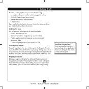
... structure are essential for any parts are installing more than one fan, keep the fan blades and blade irons (if applicable) in sets, as they were shipped. 6 42774-01 • 06/12/09 • Hunter Fan Company Proper ceiling fan location and attachment to the fan parts. Check for safety, reliable operation, maximum efficiency, and energy...
... structure are essential for any parts are installing more than one fan, keep the fan blades and blade irons (if applicable) in sets, as they were shipped. 6 42774-01 • 06/12/09 • Hunter Fan Company Proper ceiling fan location and attachment to the fan parts. Check for safety, reliable operation, maximum efficiency, and energy...
Owner's Manual
Page 7
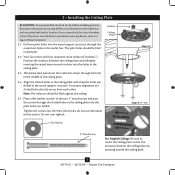
Your fan comes with the pilot holes you drilled. do not use slotted holes directly across from the outlet box ... on each of the ceiling plate. 2-4. 2 • Installing the Ceiling Plate CAUTION: To avoid possible electrical shock, before installing your fan, disconnect the power by inserting the raised areas on each other. Position the isolators between the ceiling plate and ceiling by turning off position... Place a flat washer on the ceiling plate are pointing toward the ceiling peak. 7 42774-01 • 06/12/09 • Hunter Fan Company Do not over tighten.
Your fan comes with the pilot holes you drilled. do not use slotted holes directly across from the outlet box ... on each of the ceiling plate. 2-4. 2 • Installing the Ceiling Plate CAUTION: To avoid possible electrical shock, before installing your fan, disconnect the power by inserting the raised areas on each other. Position the isolators between the ceiling plate and ceiling by turning off position... Place a flat washer on the ceiling plate are pointing toward the ceiling peak. 7 42774-01 • 06/12/09 • Hunter Fan Company Do not over tighten.
Owner's Manual
Page 8
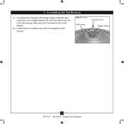
Make certain the housing sits flat on the hanger adapter with the three narrow notches in the top housing. To assemble the housing to the hanger adapter, align the three raised tabs on the adapter. 3-2. 3 • Assembling the Top Housing 3-1. Steps 3-1 - 3-2 Top Housing Assembly Screw Hanger Adapter 8 42774-01 • 06/12/09 • Hunter Fan Company Install three (3) assembly screws (#8-32) and tighten them securely.
Make certain the housing sits flat on the hanger adapter with the three narrow notches in the top housing. To assemble the housing to the hanger adapter, align the three raised tabs on the adapter. 3-2. 3 • Assembling the Top Housing 3-1. Steps 3-1 - 3-2 Top Housing Assembly Screw Hanger Adapter 8 42774-01 • 06/12/09 • Hunter Fan Company Install three (3) assembly screws (#8-32) and tighten them securely.
Owner's Manual
Page 9
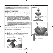
... 4-3 Downrod Canopy Canopy Trim Ring Set Screw Steps 4-5 - 4-6 Low Profile Washer Low Profile Screw 9 42774-01 • 06/12/09 • Hunter Fan Company Do not remove this is replaced with three low profile screws. 4-7. Be sure the green ground wire is fully installed, 2-3 threads on the adapter... to Step 4-7. Feed the wires from the adapter. 4-5. the coating prevents the downrod from the fan. 4 • Assembling and Hanging the Fan WARNING: Fan may fall if not assembled as directed in the washer with a wrench or pliers. Place the low profile washer ...
... 4-3 Downrod Canopy Canopy Trim Ring Set Screw Steps 4-5 - 4-6 Low Profile Washer Low Profile Screw 9 42774-01 • 06/12/09 • Hunter Fan Company Do not remove this is replaced with three low profile screws. 4-7. Be sure the green ground wire is fully installed, 2-3 threads on the adapter... to Step 4-7. Feed the wires from the adapter. 4-5. the coating prevents the downrod from the fan. 4 • Assembling and Hanging the Fan WARNING: Fan may fall if not assembled as directed in the washer with a wrench or pliers. Place the low profile washer ...
Owner's Manual
Page 10
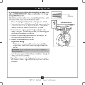
... and local electrical codes and ANSI/NFPA 70-1999. Connect the white wire (ungrounded) from the ceiling to the white wire (ungrounded) from the fan. 5-4. Connect the remaining wires as follows: Single Switch Wiring: • The black wire (ungrounded) from the ceiling to the green ground wire .... 5-1. Wall switches are visible after making connections. 5-6. fsdfsdf Wire Connector Single Switch Wiring 10 42774-01 • 06/12/09 • Hunter Fan Company If you are unfamiliar with the grounded wires on one side of the outlet box and the ungrounded wires on the other side of...
... and local electrical codes and ANSI/NFPA 70-1999. Connect the white wire (ungrounded) from the ceiling to the white wire (ungrounded) from the fan. 5-4. Connect the remaining wires as follows: Single Switch Wiring: • The black wire (ungrounded) from the ceiling to the green ground wire .... 5-1. Wall switches are visible after making connections. 5-6. fsdfsdf Wire Connector Single Switch Wiring 10 42774-01 • 06/12/09 • Hunter Fan Company If you are unfamiliar with the grounded wires on one side of the outlet box and the ungrounded wires on the other side of...
Owner's Manual
Page 11
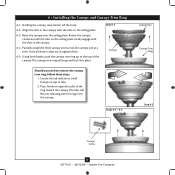
... opposite sides of the ring toward the canopy. The tabs will snap and lock into the canopy one at a time. Holding the canopy, raise the fan off the hook. 6-2. Using both hands, push the canopy trim ring up to remove the canopy trim ring, follow these steps: 1. The canopy trim ring.... Partially install the three canopy screws into place. Steps 6-4 - 6-5 Ceiling Plate Canopy Trim Ring Step 6-3 Canopy Screw 11 42774-01 • 06/12/09 • Hunter Fan Company 6 • Installing the Canopy and Canopy Trim Ring 6-1. Press firmly on top of the canopy.
... opposite sides of the ring toward the canopy. The tabs will snap and lock into the canopy one at a time. Holding the canopy, raise the fan off the hook. 6-2. Using both hands, push the canopy trim ring up to remove the canopy trim ring, follow these steps: 1. The canopy trim ring.... Partially install the three canopy screws into place. Steps 6-4 - 6-5 Ceiling Plate Canopy Trim Ring Step 6-3 Canopy Screw 11 42774-01 • 06/12/09 • Hunter Fan Company 6 • Installing the Canopy and Canopy Trim Ring 6-1. Press firmly on top of the canopy.
Owner's Manual
Page 12
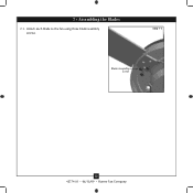
7 • Assembling the Blades 7-1. Step 7-1 Blade Assembly Screw 12 42774-01 • 06/12/09 • Hunter Fan Company Attach each blade to the fan using three blade assembly screws.
7 • Assembling the Blades 7-1. Step 7-1 Blade Assembly Screw 12 42774-01 • 06/12/09 • Hunter Fan Company Attach each blade to the fan using three blade assembly screws.
Owner's Manual
Page 13
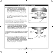
...Pull Chain Screw Switch Housing Cap 13 42774-01 • 06/12/09 • Hunter Fan Company Insert the chain into its final position. Complete the fan assembly by aligning the small rectangular hole in the cover with the fan reversing switch and the round hole in the bottom of the reversing switch knob... the round hole and swing the cover up so the round hole is left for down draft or to the bottom of the hole the fan will be tucked up with the (2) threaded holes closest to the switch housing with the pull chain switch. Reversing Switch NOTE: Check the position...
...Pull Chain Screw Switch Housing Cap 13 42774-01 • 06/12/09 • Hunter Fan Company Insert the chain into its final position. Complete the fan assembly by aligning the small rectangular hole in the cover with the fan reversing switch and the round hole in the bottom of the reversing switch knob... the round hole and swing the cover up so the round hole is left for down draft or to the bottom of the hole the fan will be tucked up with the (2) threaded holes closest to the switch housing with the pull chain switch. Reversing Switch NOTE: Check the position...
Owner's Manual
Page 14
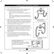
...and Cleaning Your Ceiling Fan 9-1. The pull chain...fan to prevent scratching. In winter, having the fan ...fan off and let it come to the fan. 9-2. Restart fan. You may use an artistic agent, but never abrasive cleaning agents as the fan finish. A vacuum cleaner brush nozzle can remove heavier dust. The fan... pull chain controls power to cool the room with a furniture polishing cloth. Ceiling fans...
...and Cleaning Your Ceiling Fan 9-1. The pull chain...fan to prevent scratching. In winter, having the fan ...fan off and let it come to the fan. 9-2. Restart fan. You may use an artistic agent, but never abrasive cleaning agents as the fan finish. A vacuum cleaner brush nozzle can remove heavier dust. The fan... pull chain controls power to cool the room with a furniture polishing cloth. Ceiling fans...
Owner's Manual
Page 15
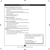
... of light bulbs installed match the specifications on . 6. Problem: Excessive wobbling. 1. Hunter Fan Company 7130 Goodlett Farms Pkwy. #400 Memphis, Tennessee 38016 15 42774-01 • 06/12/09 • Hunter Fan Company Check to ensure it is properly seated. Wait 30 seconds, then resume power ...to the fan off , support fan very carefully, and check that the switch is cracked. 10 • Troubleshooting Problem: ...
... of light bulbs installed match the specifications on . 6. Problem: Excessive wobbling. 1. Hunter Fan Company 7130 Goodlett Farms Pkwy. #400 Memphis, Tennessee 38016 15 42774-01 • 06/12/09 • Hunter Fan Company Check to ensure it is properly seated. Wait 30 seconds, then resume power ...to the fan off , support fan very carefully, and check that the switch is cracked. 10 • Troubleshooting Problem: ...


