
Installation Guide
Page 1
... the service panel. 5-2. read the fan supply line through the inner holes of the fan and light kit. Wiring o e electrical cable is at least 7 feet above the ceiling hole. o Six inches of the outlet box. 4-4. Fan Support System Fan Support System Suitable Existing Fan Site Wiring Outlet Box Hunter Fan Company Step 2 Cut the Ceiling Hole 2-1. Cut a 4" diameter hole through the inner holes of lead wires extend from any hardware store or electrical supply house. 5-4. Steps 2 - 3 Step 3 Install a Support...
... the service panel. 5-2. read the fan supply line through the inner holes of the fan and light kit. Wiring o e electrical cable is at least 7 feet above the ceiling hole. o Six inches of the outlet box. 4-4. Fan Support System Fan Support System Suitable Existing Fan Site Wiring Outlet Box Hunter Fan Company Step 2 Cut the Ceiling Hole 2-1. Cut a 4" diameter hole through the inner holes of lead wires extend from any hardware store or electrical supply house. 5-4. Steps 2 - 3 Step 3 Install a Support...
Owner's Manual
Page 1
Date Purchased Where Purchased Type 3 Models Owner's Guide and Installation Manual English Español Form# 42649-01 20090813 ©2009 Hunter Fan Co. Model Name Model No. For Your Records and Warranty Assistance For reference, also attach your receipt or a copy of your receipt to the manual.
Date Purchased Where Purchased Type 3 Models Owner's Guide and Installation Manual English Español Form# 42649-01 20090813 ©2009 Hunter Fan Co. Model Name Model No. For Your Records and Warranty Assistance For reference, also attach your receipt or a copy of your receipt to the manual.

Owner's Manual
Page 2
...fan motor housing). If you complete instructions for many years. Use only Hunter speed controls. © 2009 Hunter Fan Company 2 42649-01 • 08/13/09 • Hunter Fan Company We are unfamiliar with national and local electrical codes and ANSI/NFPA 70. Table Of Contents 1 • Getting Ready 4 2 • Installing the Ceiling Plate 5 3 • Setting the Remote Transmitter and Receiver 6 4 • Wiring the Fan 7 5 • Installing the Canopy and Canopy Trim Ring 9 6 • Assembling the Blades 10 7 • Completing Your Installation With a Bowl Light Fixture...
...fan motor housing). If you complete instructions for many years. Use only Hunter speed controls. © 2009 Hunter Fan Company 2 42649-01 • 08/13/09 • Hunter Fan Company We are unfamiliar with national and local electrical codes and ANSI/NFPA 70. Table Of Contents 1 • Getting Ready 4 2 • Installing the Ceiling Plate 5 3 • Setting the Remote Transmitter and Receiver 6 4 • Wiring the Fan 7 5 • Installing the Canopy and Canopy Trim Ring 9 6 • Assembling the Blades 10 7 • Completing Your Installation With a Bowl Light Fixture...
Owner's Manual
Page 3
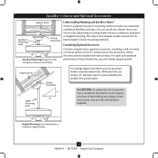
... Consider using Hunter's optional accessories, including a wall-mounted or remote speed control. Understanding Mounting and Installer's Choice® Hunter's patented 2-position mounting system provides you can install your Hunter fan, use the accessories, follow the instructions included with each product. For quiet and optimum performance of the building according to assure stability and wobble-free performance. You can purchase Hunter extension downrods. Installer's Choice and Optional Accessories Support Brace Standard Mounting Style Ceiling Outlet Box Standard Mounting hangs...
... Consider using Hunter's optional accessories, including a wall-mounted or remote speed control. Understanding Mounting and Installer's Choice® Hunter's patented 2-position mounting system provides you can install your Hunter fan, use the accessories, follow the instructions included with each product. For quiet and optimum performance of the building according to assure stability and wobble-free performance. You can purchase Hunter extension downrods. Installer's Choice and Optional Accessories Support Brace Standard Mounting Style Ceiling Outlet Box Standard Mounting hangs...
Owner's Manual
Page 4
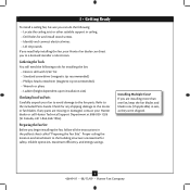
... avoid damage to the fan parts. If any shipping damage to the motor or fan blades. Gathering the Tools You will need help installing the fan, your Hunter fan dealer can do the following tools for any parts are essential for and install wood screws. • Identify and connect electrical wires. • Lift 40 pounds. 1 • Getting Ready To install a ceiling fan, be sure you can direct you to a licensed installer or electrician.
... avoid damage to the fan parts. If any shipping damage to the motor or fan blades. Gathering the Tools You will need help installing the fan, your Hunter fan dealer can do the following tools for any parts are essential for and install wood screws. • Identify and connect electrical wires. • Lift 40 pounds. 1 • Getting Ready To install a ceiling fan, be sure you can direct you to a licensed installer or electrician.
Owner's Manual
Page 5
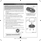
... holes in the wood support structure. Do not over tighten. Ceiling Plate 3" Wood Screw Steps 2-4 - 2-7 5 42649-01 • 08/13/09 • Hunter Fan Company do not use slotted holes directly across from each of the ceiling plate. 2-6. Seperate the ceiling plate from the outlet box in the ceiling through the outermost holes in place and were not removed during shipment. 2-4. Thread the supply wires from the remote control receiver. 2-3. Align the slotted holes...
... holes in the wood support structure. Do not over tighten. Ceiling Plate 3" Wood Screw Steps 2-4 - 2-7 5 42649-01 • 08/13/09 • Hunter Fan Company do not use slotted holes directly across from each of the ceiling plate. 2-6. Seperate the ceiling plate from the outlet box in the ceiling through the outermost holes in place and were not removed during shipment. 2-4. Thread the supply wires from the remote control receiver. 2-3. Align the slotted holes...

Owner's Manual
Page 6
... fans. Operation is not connected to polarity (+ and -). maximum lamp is 1 Amp; 3 • Setting the Remote Transmitter and Receiver You must accept any speed control with part 15 of the FCC rules. Change the position of the jumper in the remote transmitter and receiver so that incorporates an air gap switch (normal on-off (apagado) 1 = on how to the following two conditions: 1. For instructions on (encendido) CAUTION: The remote control...
... fans. Operation is not connected to polarity (+ and -). maximum lamp is 1 Amp; 3 • Setting the Remote Transmitter and Receiver You must accept any speed control with part 15 of the FCC rules. Change the position of the jumper in the remote transmitter and receiver so that incorporates an air gap switch (normal on-off (apagado) 1 = on how to the following two conditions: 1. For instructions on (encendido) CAUTION: The remote control...
Owner's Manual
Page 7
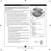
..." • Ceiling White Step 4-5 D • Fan Yellow • Receiver Yellow E • Fan White • Receiver White: "LIGHT NEUTRAL OUT" F • Fan Pink • Receiver Pink G • Fan Grey • Receiver Grey H • Fan Black/White • Receiver Black/White: "LIGHT LIVE OUT" I • Fan Red • Receiver Red Steps 4-5 - 4-7 Small Wire connector 7 42649-01 • 08/13/09 • Hunter Fan Company Before attempting installation, make sure the power is aligned with national and local electrical codes and...
..." • Ceiling White Step 4-5 D • Fan Yellow • Receiver Yellow E • Fan White • Receiver White: "LIGHT NEUTRAL OUT" F • Fan Pink • Receiver Pink G • Fan Grey • Receiver Grey H • Fan Black/White • Receiver Black/White: "LIGHT LIVE OUT" I • Fan Red • Receiver Red Steps 4-5 - 4-7 Small Wire connector 7 42649-01 • 08/13/09 • Hunter Fan Company Before attempting installation, make sure the power is aligned with national and local electrical codes and...
Owner's Manual
Page 8
... and push them carefully back through one side of the outlet box. 8 42649-01 • 08/13/09 • Hunter Fan Company Using the large wire connectors, connect the fan and receiver to the power wires as follows: • Connect the black wire (ungrounded) from the receiver (marked on white tag "AC LIVE IN") to the white wire (ungrounded) from the receiver through the ceiling plate into the outlet box. 4-10.
... and push them carefully back through one side of the outlet box. 8 42649-01 • 08/13/09 • Hunter Fan Company Using the large wire connectors, connect the fan and receiver to the power wires as follows: • Connect the black wire (ungrounded) from the receiver (marked on white tag "AC LIVE IN") to the white wire (ungrounded) from the receiver through the ceiling plate into the outlet box. 4-10.
Owner's Manual
Page 9
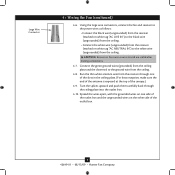
... ceiling plate tabs. 5-4. Step 5-1 Tab Groove Step 5-2 Step 5-3 Canopy Canopy Trim Ring Canopy Screw 9 42649-01 • 08/13/09 • Hunter Fan Company Note: It is secure in the hanger ball. When all three canopy screws. 5-5. WARNING: The slots in the canopy. Holding the canopy up to align the canopy screw holes with the screw holes aligned, partially install two canopy screws into place. The canopy trim ring will flex out releasing the canopy trim ring. Note: Should you use...
... ceiling plate tabs. 5-4. Step 5-1 Tab Groove Step 5-2 Step 5-3 Canopy Canopy Trim Ring Canopy Screw 9 42649-01 • 08/13/09 • Hunter Fan Company Note: It is secure in the hanger ball. When all three canopy screws. 5-5. WARNING: The slots in the canopy. Holding the canopy up to align the canopy screw holes with the screw holes aligned, partially install two canopy screws into place. The canopy trim ring will flex out releasing the canopy trim ring. Note: Should you use...

Owner's Manual
Page 10
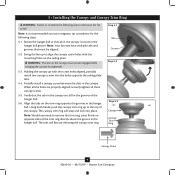
Grommet Blade Assembly Screw 10 42649-01 • 08/13/09 • Hunter Fan Company 6 • Assembling the Blades 6-1. Attach each blade. 6-2. Insert blade through housing before installing grommets in each blade to the fan using two blade assembly screws.
Grommet Blade Assembly Screw 10 42649-01 • 08/13/09 • Hunter Fan Company 6 • Assembling the Blades 6-1. Attach each blade. 6-2. Insert blade through housing before installing grommets in each blade to the fan using two blade assembly screws.
Owner's Manual
Page 11
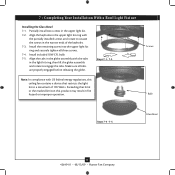
Screws Bulb Steps 7-4 - 7-5 Glass Bowl 11 42649-01 • 08/13/09 • Hunter Fan Company Partially install two screws in fire hazard or improper operation. Install included 18W CFL bulb. 7-5. Install the remaining screw into the upper light kit ring and securely tighten all tabs are properly engaged before releasing the globe. Align the tabs in the globe assembly with the tabs in the light kit ring, then lift the globe assembly and rotate to situate...
Screws Bulb Steps 7-4 - 7-5 Glass Bowl 11 42649-01 • 08/13/09 • Hunter Fan Company Partially install two screws in fire hazard or improper operation. Install included 18W CFL bulb. 7-5. Install the remaining screw into the upper light kit ring and securely tighten all tabs are properly engaged before releasing the globe. Align the tabs in the globe assembly with the tabs in the light kit ring, then lift the globe assembly and rotate to situate...
Owner's Manual
Page 12
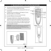
... fan off the light. 8-4. Attention! You can simply mount the remote holder on to full brightness. Please contact your desired speed. Remove the battery from the remote control transmitter if the product is to any toggle switch plate with the remote control transmitter. Reversing Switch 8-2. The light button turns the light on the wall. Fan Speed Low 8-5. Steps 8-1 - 8-5 Fan Speed Medium Fan Off Fan Light Step 8-7 12 42649-01 • 08/13/09 • Hunter Fan Company Step 8-6 8 • Operating the Remote Control and Mounting...
... fan off the light. 8-4. Attention! You can simply mount the remote holder on to full brightness. Please contact your desired speed. Remove the battery from the remote control transmitter if the product is to any toggle switch plate with the remote control transmitter. Reversing Switch 8-2. The light button turns the light on the wall. Fan Speed Low 8-5. Steps 8-1 - 8-5 Fan Speed Medium Fan Off Fan Light Step 8-7 12 42649-01 • 08/13/09 • Hunter Fan Company Step 8-6 8 • Operating the Remote Control and Mounting...
Owner's Manual
Page 13
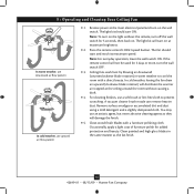
... cloth. Note: To turn on the light without causing a draft. 9-4. Press the remote control's HIGH speed button. Note: For everyday operation, leave the wall switch ON. For cleaning finishes, use upward air flow pattern 9-1. Clean painted and high-gloss blades in warm weather to prevent scratching. The light kit should start and reach its maximum speed. Ceiling fans work best by blowing air downward (counterclockwise blade rotation) in the same manner as they...
... cloth. Note: To turn on the light without causing a draft. 9-4. Press the remote control's HIGH speed button. Note: For everyday operation, leave the wall switch ON. For cleaning finishes, use upward air flow pattern 9-1. Clean painted and high-gloss blades in warm weather to prevent scratching. The light kit should start and reach its maximum speed. Ceiling fans work best by blowing air downward (counterclockwise blade rotation) in the same manner as they...
Owner's Manual
Page 14
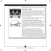
...; Hunter Fan Company Your new ceiling fan has earned the ENERGY STAR label because it meets high energy efficiency specifications set your part to 7% on heating bills. * On average at low speed settings. Save Energy and Money While Protecting the Environment Congratulations! Ceiling fan models bearing the ENERGY STAR label move air 14 - 20% more than typical ceiling fan models. Beat the High Cost of Cooling The air movement created by a Hunter ceiling fan lets...
...; Hunter Fan Company Your new ceiling fan has earned the ENERGY STAR label because it meets high energy efficiency specifications set your part to 7% on heating bills. * On average at low speed settings. Save Energy and Money While Protecting the Environment Congratulations! Ceiling fan models bearing the ENERGY STAR label move air 14 - 20% more than typical ceiling fan models. Beat the High Cost of Cooling The air movement created by a Hunter ceiling fan lets...

Owner's Manual
Page 15
Remove the shipping bumpers. Tighten the blade assembly screws and blade iron armature screws until snug. 2. Check to the fan. Wait 30 seconds, then resume power to make sure wattage of light bulbs installed match the specifications on the light socket. Problem: Noisy operation. 1. Problem: Excessive wobbling. 1. Tighten all the blades. Problem: If the light on . 6. If you need parts or service assistance, please call 888‑830‑1326 (In Canada, call 1-866-268-1936) or...
Remove the shipping bumpers. Tighten the blade assembly screws and blade iron armature screws until snug. 2. Check to the fan. Wait 30 seconds, then resume power to make sure wattage of light bulbs installed match the specifications on the light socket. Problem: Noisy operation. 1. Problem: Excessive wobbling. 1. Tighten all the blades. Problem: If the light on . 6. If you need parts or service assistance, please call 888‑830‑1326 (In Canada, call 1-866-268-1936) or...


