

Installation Guide
Page 1
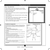
... fan and light kit. If you are unfamiliar with the rotating fan blades during normal operation. • e fan blades are aligned with national and local electrical codes and ANSI/NFPA 70. Wiring o e electrical cable is there, determine if it will hold full weight of the outlet box are at least 7 feet above the ceiling hole. Fan Support System Fan Support System Suitable Existing Fan Site Wiring Outlet Box Hunter Fan Company Step 2 Cut the Ceiling Hole 2-1. Locate...
... fan and light kit. If you are unfamiliar with the rotating fan blades during normal operation. • e fan blades are aligned with national and local electrical codes and ANSI/NFPA 70. Wiring o e electrical cable is there, determine if it will hold full weight of the outlet box are at least 7 feet above the ceiling hole. Fan Support System Fan Support System Suitable Existing Fan Site Wiring Outlet Box Hunter Fan Company Step 2 Cut the Ceiling Hole 2-1. Locate...

Owner's Manual
Page 1
Date Purchased Where Purchased Type 2 Models Owner's Guide and Installation Manual English Español Form# 42440-01 20110404 ©2011 Hunter Fan Co. For Your Records and Warranty Assistance For reference, also attach your receipt or a copy of your receipt to the manual. Model Name Model No.
Date Purchased Where Purchased Type 2 Models Owner's Guide and Installation Manual English Español Form# 42440-01 20110404 ©2011 Hunter Fan Co. For Your Records and Warranty Assistance For reference, also attach your receipt or a copy of your receipt to the manual. Model Name Model No.

Owner's Manual
Page 2
... THESE INSTRUCTIONS. • Use only Hunter replacement parts. • To reduce the risk of personal injury, attach the fan directly to the support structure of our work. Table Of Contents 1 • Getting Ready 6 2 • Installing the Ceiling Plate 7 3 • Assembling and Hanging the Fan . . . 8 4 • Wiring the Fan 9 5 • Installing the Canopy and Canopy Trim Ring 10 6 • Assembling the Blades 11 7 • Completing Your Installation With or Without a Bowl Light Fixture 12 8 • Operating and Cleaning Your Ceiling Fan 16 9 • Troubleshooting...
... THESE INSTRUCTIONS. • Use only Hunter replacement parts. • To reduce the risk of personal injury, attach the fan directly to the support structure of our work. Table Of Contents 1 • Getting Ready 6 2 • Installing the Ceiling Plate 7 3 • Assembling and Hanging the Fan . . . 8 4 • Wiring the Fan 9 5 • Installing the Canopy and Canopy Trim Ring 10 6 • Assembling the Blades 11 7 • Completing Your Installation With or Without a Bowl Light Fixture 12 8 • Operating and Cleaning Your Ceiling Fan 16 9 • Troubleshooting...
Owner's Manual
Page 3
... Section 2 • Installing the Ceiling Plate. Outlet Box • The outlet box is recessed a minimum of the fan. 30" From Wall or Nearest Obstruction 7' Minimum Blades to the joist or support brace by an approved connector. • Six inches of the fan and light kit. Fan Support System Fan Support System Suitable Existing Fan Site Wiring Outlet Box 3 42440-01 • 04/04/11 • Hunter Fan Company Choose the Fan Site Proper ceiling fan location and attachment...
... Section 2 • Installing the Ceiling Plate. Outlet Box • The outlet box is recessed a minimum of the fan. 30" From Wall or Nearest Obstruction 7' Minimum Blades to the joist or support brace by an approved connector. • Six inches of the fan and light kit. Fan Support System Fan Support System Suitable Existing Fan Site Wiring Outlet Box 3 42440-01 • 04/04/11 • Hunter Fan Company Choose the Fan Site Proper ceiling fan location and attachment...

Owner's Manual
Page 4
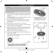
... approved connector, available at least 6" beyond the box. 5-3. Attach the fan supply line to your ceiling fan site. Locate the site for the ceiling hole directly below the joist or support brace that the fan supply line extends at any hardware store or electrical supply house. 4-2. Attach a 2" x 4" support brace between two joists. The bottom of 1/16" into the ceiling. Prepare the Wiring 5-1. For instructions to install your ceiling fan, go...
... approved connector, available at least 6" beyond the box. 5-3. Attach the fan supply line to your ceiling fan site. Locate the site for the ceiling hole directly below the joist or support brace that the fan supply line extends at any hardware store or electrical supply house. 4-2. Attach a 2" x 4" support brace between two joists. The bottom of 1/16" into the ceiling. Prepare the Wiring 5-1. For instructions to install your ceiling fan, go...

Owner's Manual
Page 5
... the ceiling by a downrod (included). Considering Optional Accessories Consider using Hunter's optional accessories, including a wall-mounted or remote speed control. The steps in one of three ways, depending on ceiling height and your Hunter fan, use the accessories, follow the instructions included with each product. Support Brace Ceiling Outlet Box For ceilings higher than 8 feet high CAUTION: To reduce the risk of personal injury, attach the fan directly to the support structure of your preference: Low Profile...
... the ceiling by a downrod (included). Considering Optional Accessories Consider using Hunter's optional accessories, including a wall-mounted or remote speed control. The steps in one of three ways, depending on ceiling height and your Hunter fan, use the accessories, follow the instructions included with each product. Support Brace Ceiling Outlet Box For ceilings higher than 8 feet high CAUTION: To reduce the risk of personal injury, attach the fan directly to the support structure of your preference: Low Profile...

Owner's Manual
Page 6
... fan parts. Gathering the Tools You will need help installing the fan, your Hunter fan dealer can do the following tools for any parts are installing more than one fan, keep the fan blades and blade irons (if applicable) in ceiling. • Drill holes for and install wood screws. • Identify and connect electrical wires. • Lift 40 pounds. Installing Multiple Fans? 1 • Getting Ready To install a ceiling fan, be sure you can direct you to the motor or fan blades...
... fan parts. Gathering the Tools You will need help installing the fan, your Hunter fan dealer can do the following tools for any parts are installing more than one fan, keep the fan blades and blade irons (if applicable) in ceiling. • Drill holes for and install wood screws. • Identify and connect electrical wires. • Lift 40 pounds. Installing Multiple Fans? 1 • Getting Ready To install a ceiling fan, be sure you can direct you to the motor or fan blades...
Owner's Manual
Page 7
.... Thread the supply wires from each of the ceiling plate. 2-5. Tighten the screws into the wood support structure through the slotted holes in the ceiling plate into the pilot holes you drilled in the outlet box. Ceiling Plate 3" Wood Screw Steps 2-3 - 2-6 7 42440-01 • 04/04/11 • Hunter Fan Company 2 • Installing the Ceiling Plate CAUTION: To avoid possible electrical shock, before installing your fan, disconnect the power by turning off position...
.... Thread the supply wires from each of the ceiling plate. 2-5. Tighten the screws into the wood support structure through the slotted holes in the ceiling plate into the pilot holes you drilled in the outlet box. Ceiling Plate 3" Wood Screw Steps 2-3 - 2-6 7 42440-01 • 04/04/11 • Hunter Fan Company 2 • Installing the Ceiling Plate CAUTION: To avoid possible electrical shock, before installing your fan, disconnect the power by turning off position...

Owner's Manual
Page 8
... Fan may fall if not assembled as directed in the ball. 3-3. Standard or Angled Mounting Steps 3-2 - 3-3 Downrod Set Screw Canopy Canopy Trim Ring Low Profile Mounting Steps 3-5 - 3-6 Low Profile Screws Green Ground Wire Canopy Trim Ring Low Profile Washer Canopy Low Profile Screw Step 3-6 (Detail) Adapter Low Profile Screw Low Profile Washer 8 42440-01 • 04/04/11 • Hunter Fan Company Feed the wires from the fan. CAUTION: The adapter has a special coating on the pipe will still be visible; Once assembled, do not remove the downrod. Place the low profile washer...
... Fan may fall if not assembled as directed in the ball. 3-3. Standard or Angled Mounting Steps 3-2 - 3-3 Downrod Set Screw Canopy Canopy Trim Ring Low Profile Mounting Steps 3-5 - 3-6 Low Profile Screws Green Ground Wire Canopy Trim Ring Low Profile Washer Canopy Low Profile Screw Step 3-6 (Detail) Adapter Low Profile Screw Low Profile Washer 8 42440-01 • 04/04/11 • Hunter Fan Company Feed the wires from the fan. CAUTION: The adapter has a special coating on the pipe will still be visible; Once assembled, do not remove the downrod. Place the low profile washer...
Owner's Manual
Page 9
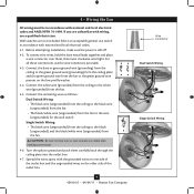
... unfamiliar with wiring, use switch in accordance with the grounded wires on one side of the outlet box. 9 42440-01 • 04/04/11 • Hunter Fan Company Wire Connector Dual Switch Wiring Single Switch Wiring For all these connections use the wire connectors provided. 4-3. Connect the white wire (grounded) from the ceiling to the green ground wire (grounding) from the ceiling plate and the green ground wire from the fan. 4-5. Before attempting installation, make sure the power is...
... unfamiliar with wiring, use switch in accordance with the grounded wires on one side of the outlet box. 9 42440-01 • 04/04/11 • Hunter Fan Company Wire Connector Dual Switch Wiring Single Switch Wiring For all these connections use the wire connectors provided. 4-3. Connect the white wire (grounded) from the ceiling to the green ground wire (grounding) from the ceiling plate and the green ground wire from the fan. 4-5. Before attempting installation, make sure the power is...

Owner's Manual
Page 10
... install two canopy screws into the holes opposite the ceiling plate tabs. 5-4. Note: It is secure in the hanger ball. Using both hands, push the canopy trim ring up with the mounting holes on the trim ring opposite the grooves in the hanger ball groove. Step 5-1 Tab Groove Step 5-2 Step 5-3 Canopy Canopy Trim Ring Canopy Screw 10 42440-01 • 04/04/11 • Hunter Fan Company The canopy trim ring will flex out releasing the canopy trim ring. Partially install a canopy screw into...
... install two canopy screws into the holes opposite the ceiling plate tabs. 5-4. Note: It is secure in the hanger ball. Using both hands, push the canopy trim ring up with the mounting holes on the trim ring opposite the grooves in the hanger ball groove. Step 5-1 Tab Groove Step 5-2 Step 5-3 Canopy Canopy Trim Ring Canopy Screw 10 42440-01 • 04/04/11 • Hunter Fan Company The canopy trim ring will flex out releasing the canopy trim ring. Partially install a canopy screw into...

Owner's Manual
Page 11
... Armor on the blades. 6-2. Attach each blade, insert one blade mounting screw through the blade iron, and attach lightly to the fan. If your fan has grommets, insert them by hand into the holes on the blades. Insert the second blade mounting screw, then securely tighten both mounting screws. 6 • Assembling the Blades Hunter fans use a furniture polish or any other cleaners that hold the blade to the fan). 6-1. Remove the blade mounting screws and rubber shipping bumpers from the motor. Use a dry or...
... Armor on the blades. 6-2. Attach each blade, insert one blade mounting screw through the blade iron, and attach lightly to the fan. If your fan has grommets, insert them by hand into the holes on the blades. Insert the second blade mounting screw, then securely tighten both mounting screws. 6 • Assembling the Blades Hunter fans use a furniture polish or any other cleaners that hold the blade to the fan). 6-1. Remove the blade mounting screws and rubber shipping bumpers from the motor. Use a dry or...

Owner's Manual
Page 12
... screws are installing a light fixture. Steps 7-1 - 7-3 Housing Assembly Screw Upper Switch Housing 12 42440-01 • 04/04/11 • Hunter Fan Company To attach the upper switch housing, partially install two housing assembly screws into the housing. If you do not want to install the light fixture, proceed with this fan model. 7-1. WARNING: Use only the light fixture supplied with step 7-6 now. 7 • Completing Your Installation With or Without a Bowl Light Fixture Your Hunter fan comes with the housing assembly screws. 7-4. Feed the upper plug connector...
... screws are installing a light fixture. Steps 7-1 - 7-3 Housing Assembly Screw Upper Switch Housing 12 42440-01 • 04/04/11 • Hunter Fan Company To attach the upper switch housing, partially install two housing assembly screws into the housing. If you do not want to install the light fixture, proceed with this fan model. 7-1. WARNING: Use only the light fixture supplied with step 7-6 now. 7 • Completing Your Installation With or Without a Bowl Light Fixture Your Hunter fan comes with the housing assembly screws. 7-4. Feed the upper plug connector...

Owner's Manual
Page 13
... the lower switch housing, connect the upper plug connector from the motor to the light socket(s) may result in the upper and lower switch housings. 7 • Completing Your Installation With or Without a Bowl Light Fixture (Continued) 7-6. Incorrect connection could cause improper operation and damage to be operating properly, see the troubleshooting section. If lights do not appear to the product. 7-7. Steps 7-6 - 7-7 Lower Switch Housing Plug Connector Detail Plug Connector Housing Assembly Screw 13 42440-01 • 04/04/11 • Hunter Fan Company
... the lower switch housing, connect the upper plug connector from the motor to the light socket(s) may result in the upper and lower switch housings. 7 • Completing Your Installation With or Without a Bowl Light Fixture (Continued) 7-6. Incorrect connection could cause improper operation and damage to be operating properly, see the troubleshooting section. If lights do not appear to the product. 7-7. Steps 7-6 - 7-7 Lower Switch Housing Plug Connector Detail Plug Connector Housing Assembly Screw 13 42440-01 • 04/04/11 • Hunter Fan Company

Owner's Manual
Page 14
...; Hunter Fan Company Attach the extra pull chains (included) to the light and fan pull chains using the breakaway connector. (You may find the breakaway connector on the end of the cover plate. 7-10. Then, thread the light pull chain through the grommet hole in the cover plate and glass bowl. 7-12. First install B10 candelabra bulbs (60 Watt Maximum) into the sockets. 7-9. Place the cover plate up against the glass bowl. Thread the light and fan pull chains through the finial and screw the finial...
...; Hunter Fan Company Attach the extra pull chains (included) to the light and fan pull chains using the breakaway connector. (You may find the breakaway connector on the end of the cover plate. 7-10. Then, thread the light pull chain through the grommet hole in the cover plate and glass bowl. 7-12. First install B10 candelabra bulbs (60 Watt Maximum) into the sockets. 7-9. Place the cover plate up against the glass bowl. Thread the light and fan pull chains through the finial and screw the finial...

Owner's Manual
Page 15
... plug connectors between the black wire and the red wire. 7-15. Steps 7-17 - 7-19 Lower Switch Housing Male Dummy Terminal Female Dummy Terminal Cap Plug Button Step 7-20 15 42440-01 • 04/04/11 • Hunter Fan Company Install the switch housing cap and plug button to the lower switch housing. 7-21. Once you have uninstalled the light fixture, continue with Step 7‑6. To uninstall the light fixture, first disconnect the plug connectors between the two white wires...
... plug connectors between the black wire and the red wire. 7-15. Steps 7-17 - 7-19 Lower Switch Housing Male Dummy Terminal Female Dummy Terminal Cap Plug Button Step 7-20 15 42440-01 • 04/04/11 • Hunter Fan Company Install the switch housing cap and plug button to the lower switch housing. 7-21. Once you have uninstalled the light fixture, continue with Step 7‑6. To uninstall the light fixture, first disconnect the plug connectors between the two white wires...

Owner's Manual
Page 16
...; Hunter Fan Company The fan pull chain controls power to clean the blades. The pull chain has four settings in warm weather to the light. Reversing Switch In warm weather, use downward air flow pattern In cold weather, use a furniture polish or any residue, as they will distribute the warmer air trapped at the ceiling around the room without causing a draft. 8-5. A vacuum cleaner brush nozzle can remove heavier dust. Slide the reversing switch on the fan...
...; Hunter Fan Company The fan pull chain controls power to clean the blades. The pull chain has four settings in warm weather to the light. Reversing Switch In warm weather, use downward air flow pattern In cold weather, use a furniture polish or any residue, as they will distribute the warmer air trapped at the ceiling around the room without causing a draft. 8-5. A vacuum cleaner brush nozzle can remove heavier dust. Slide the reversing switch on the fan...

Owner's Manual
Page 17
...; Hunter Fan Company Loosen canopy, check all blade iron screws. 3. Turn power off suddenly, but fan is still operating 1. Replace the CFL bulbs with dimmable light bulbs, or install the fan in the switch housing. 4. Problem: Lights shut off , support fan very carefully, and check that are not usually made for dimming. Turn power on the MAX wattage sticker affixed to make sure the wattage and type of the light bulbs that the hanger ball is cracked. Tighten the blade bracket screws until...
...; Hunter Fan Company Loosen canopy, check all blade iron screws. 3. Turn power off suddenly, but fan is still operating 1. Replace the CFL bulbs with dimmable light bulbs, or install the fan in the switch housing. 4. Problem: Lights shut off , support fan very carefully, and check that are not usually made for dimming. Turn power on the MAX wattage sticker affixed to make sure the wattage and type of the light bulbs that the hanger ball is cracked. Tighten the blade bracket screws until...

Parts Guide
Page 1
.... Parts List Item Name Hanging System Kit Ceiling Plate Canopy Canopy Trim Ring Hanger Ball / Downrod Assembly Setscrew Low Profile Washer Canopy Screw Wood Screw Wood Screw Flat Washer Screw, Low Profile Switch Housing Assembly Switch Housing Cover Switch Housing Plug Button Blade Iron Set Blade Set Screw, Blade Iron Armature Light Kit Assembly Hardware Kit Blade Assembly Screw Screw, Machine, 6-32 Wire Connector Screw, Switch Housing Assembly Balancing Kit Pull Chain Pull Chain Pull Chain Pendant Dummy Terminal, Male Dummy Terminal, Female Cap, Finial Light bulb / Bulb Finial Globe/Shade...
.... Parts List Item Name Hanging System Kit Ceiling Plate Canopy Canopy Trim Ring Hanger Ball / Downrod Assembly Setscrew Low Profile Washer Canopy Screw Wood Screw Wood Screw Flat Washer Screw, Low Profile Switch Housing Assembly Switch Housing Cover Switch Housing Plug Button Blade Iron Set Blade Set Screw, Blade Iron Armature Light Kit Assembly Hardware Kit Blade Assembly Screw Screw, Machine, 6-32 Wire Connector Screw, Switch Housing Assembly Balancing Kit Pull Chain Pull Chain Pull Chain Pendant Dummy Terminal, Male Dummy Terminal, Female Cap, Finial Light bulb / Bulb Finial Globe/Shade...


