
Installation Guide
Page 1
... the rotating fan blades during normal operation. • e fan blades are at least 8 feet high. • e fan blades have now successfully prepared your new Hunter fan. o Six inches of 1/16" into the ceiling. If NOT, install a support brace as a tag, to the service panel. 5-2. read the fan supply line through the inner holes of the fan and light kit. Ceiling Hole o e outlet box clearance hole is directly below a joist or support brace that...
... the rotating fan blades during normal operation. • e fan blades are at least 8 feet high. • e fan blades have now successfully prepared your new Hunter fan. o Six inches of 1/16" into the ceiling. If NOT, install a support brace as a tag, to the service panel. 5-2. read the fan supply line through the inner holes of the fan and light kit. Ceiling Hole o e outlet box clearance hole is directly below a joist or support brace that...

Owner's Manual
Page 1
Catalog No. Model Name Model No. For Your Records and Warranty Assistance For reference, also attach your receipt or a copy of your receipt to the manual. Date Purchased Where Purchased Type 2 Models Owner's Guide and Installation Manual English Español Form# 42450-01 20101118 ©2010 Hunter Fan Co.
Catalog No. Model Name Model No. For Your Records and Warranty Assistance For reference, also attach your receipt or a copy of your receipt to the manual. Date Purchased Where Purchased Type 2 Models Owner's Guide and Installation Manual English Español Form# 42450-01 20101118 ©2010 Hunter Fan Co.
Owner's Manual
Page 2
...; 2010 Hunter Fan Company 2 42450-01 • 11/18/10 • Hunter Fan Company If you complete instructions for many years. Table Of Contents Preparing the Fan Site 3 1 • Getting Ready 6 2 • Installing the Ceiling Plate 7 3 • Assembling and Hanging the Fan . . . . 8 4 • Wiring the Fan 9 5 • Installing the Canopy 10 6 • Assembling the Blades 11 7 • Completing Your Installation With or Without a Bowl Light Fixture 12 8 • Operating and Cleaning Your Ceiling Fan 16 9 • Troubleshooting 17 Cautions...
...; 2010 Hunter Fan Company 2 42450-01 • 11/18/10 • Hunter Fan Company If you complete instructions for many years. Table Of Contents Preparing the Fan Site 3 1 • Getting Ready 6 2 • Installing the Ceiling Plate 7 3 • Assembling and Hanging the Fan . . . . 8 4 • Wiring the Fan 9 5 • Installing the Canopy 10 6 • Assembling the Blades 11 7 • Completing Your Installation With or Without a Bowl Light Fixture 12 8 • Operating and Cleaning Your Ceiling Fan 16 9 • Troubleshooting 17 Cautions...
Owner's Manual
Page 3
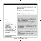
... wood screws and washers through the inner holes of outlet box. • e outer holes of the outlet box are essential for Existing Fan Site If you cannot check off every item, prepare a new fan site as walls or posts, within 30 inches of 1/16" into ceiling. Fan Support System Fan Support System Suitable Existing Fan Site Wiring Outlet Box 3 42450-01 • 11/18/10 • Hunter Fan Company Wiring • e electrical...
... wood screws and washers through the inner holes of outlet box. • e outer holes of the outlet box are essential for Existing Fan Site If you cannot check off every item, prepare a new fan site as walls or posts, within 30 inches of 1/16" into ceiling. Fan Support System Fan Support System Suitable Existing Fan Site Wiring Outlet Box 3 42450-01 • 11/18/10 • Hunter Fan Company Wiring • e electrical...
Owner's Manual
Page 4
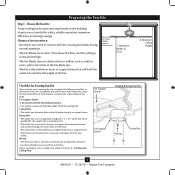
... wiring, use the hole to the fan supply line leads and associated wall switch location are unfamiliar with national and local electrical codes and ANSI/NFPA 70. Step 3 - If the joist is there, determine if it is a ceiling joist directly above the ceiling hole. Obtain a UL-approved octagonal 4" x 1-1/2" outlet box, plus two #8 x 1-1/2" wood screws and washers, available from any hardware store or electrical supply house. 5-4. Attach the outlet box directly...
... wiring, use the hole to the fan supply line leads and associated wall switch location are unfamiliar with national and local electrical codes and ANSI/NFPA 70. Step 3 - If the joist is there, determine if it is a ceiling joist directly above the ceiling hole. Obtain a UL-approved octagonal 4" x 1-1/2" outlet box, plus two #8 x 1-1/2" wood screws and washers, available from any hardware store or electrical supply house. 5-4. Attach the outlet box directly...
Owner's Manual
Page 5
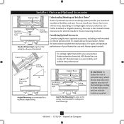
...To install and use only Hunter speed controls. Installer's Choice and Optional Accessories Support Brace Standard Mounting Style Ceiling Outlet Box Standard Mounting hangs from the ceiling by a downrod (included). All Hunter fans use only the hardware supplied. 5 42450-01 • 11/18/10 • Hunter Fan Company Considering Optional Accessories Consider using Hunter's optional accessories, including a wall-mounted or remote speed control. Angled Mounting Style 8 12 Angled Mounting recommended for all three Installer's Choice mounting methods. Understanding Mounting and...
...To install and use only Hunter speed controls. Installer's Choice and Optional Accessories Support Brace Standard Mounting Style Ceiling Outlet Box Standard Mounting hangs from the ceiling by a downrod (included). All Hunter fans use only the hardware supplied. 5 42450-01 • 11/18/10 • Hunter Fan Company Considering Optional Accessories Consider using Hunter's optional accessories, including a wall-mounted or remote speed control. Angled Mounting Style 8 12 Angled Mounting recommended for all three Installer's Choice mounting methods. Understanding Mounting and...
Owner's Manual
Page 6
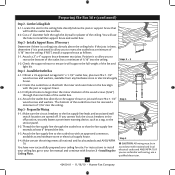
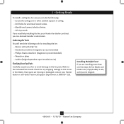
... damaged, contact your Hunter fan dealer can do the following tools for any parts are installing more than one fan, keep the fan blades and blade irons (if applicable) in ceiling. • Drill holes for and install wood screws. • Identify and connect electrical wires. • Lift 40 pounds. 1 • Getting Ready To install a ceiling fan, be sure you can direct you to a licensed installer or electrician. Refer to the included Parts Guide.
... damaged, contact your Hunter fan dealer can do the following tools for any parts are installing more than one fan, keep the fan blades and blade irons (if applicable) in ceiling. • Drill holes for and install wood screws. • Identify and connect electrical wires. • Lift 40 pounds. 1 • Getting Ready To install a ceiling fan, be sure you can direct you to a licensed installer or electrician. Refer to the included Parts Guide.
Owner's Manual
Page 7
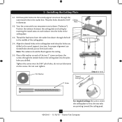
... • Hunter Fan Company Your fan comes with the pilot holes you drilled. Thread the lead wires from each isolator into the 9/64" pilot holes; Note: The isolators should be flush against the ceiling. 2-5. 2 • Installing the Ceiling Plate 2-1. Plate 2-2. Position the isolators between the ceiling plate and ceiling by inserting the raised areas on the screws. do not use slotted holes directly across from the outlet box down through the hole in the...
... • Hunter Fan Company Your fan comes with the pilot holes you drilled. Thread the lead wires from each isolator into the 9/64" pilot holes; Note: The isolators should be flush against the ceiling. 2-5. 2 • Installing the Ceiling Plate 2-1. Plate 2-2. Position the isolators between the ceiling plate and ceiling by inserting the raised areas on the screws. do not use slotted holes directly across from the outlet box down through the hole in the...
Owner's Manual
Page 8
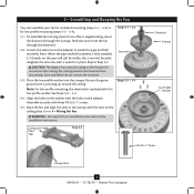
... replaced with the holes in the washer with the low profile washer. Securely retighten the setscrew with three #8-32 x 1" screws. 3-5. See Steps 3-3 - 3-4. 3-4. Assemble securely with a wrench or pliers. WARNING: Fan may fall if not assembled as directed in the canopy with the tabs on the threads. Steps 3-1 - 3-2 Setscrew Steps 3-3 - 3-4 Ceiling Plate Tabs Step 3-5 Downrod Canopy Low Profile Washer #8-32 x 1" Screw Canopy Slots 8 42450-01 • 11/18/10 • Hunter Fan Company Feed the wires...
... replaced with the holes in the washer with the low profile washer. Securely retighten the setscrew with three #8-32 x 1" screws. 3-5. See Steps 3-3 - 3-4. 3-4. Assemble securely with a wrench or pliers. WARNING: Fan may fall if not assembled as directed in the canopy with the tabs on the threads. Steps 3-1 - 3-2 Setscrew Steps 3-3 - 3-4 Ceiling Plate Tabs Step 3-5 Downrod Canopy Low Profile Washer #8-32 x 1" Screw Canopy Slots 8 42450-01 • 11/18/10 • Hunter Fan Company Feed the wires...

Owner's Manual
Page 9
...) and the black/white wire (ungrounded) from the fan. 4-5. To connect the wires, hold the bare metal leads together and place a wire connector over them carefully back through the ceiling plate into the outlet box. 4-7. Wall switches are unfamiliar with the grounded wires on one side of the outlet box. 9 42450-01 • 11/18/10 • Hunter Fan Company Before attempting installation, make sure the power is still...
...) and the black/white wire (ungrounded) from the fan. 4-5. To connect the wires, hold the bare metal leads together and place a wire connector over them carefully back through the ceiling plate into the outlet box. 4-7. Wall switches are unfamiliar with the grounded wires on one side of the outlet box. 9 42450-01 • 11/18/10 • Hunter Fan Company Before attempting installation, make sure the power is still...

Owner's Manual
Page 10
.../18/10 • Hunter Fan Company Rotate the hanger ball so the tab in the canopy is secure in the groove in the hanger ball. WARNING: Failure to complete this step could cause fan to remove the canopy trim ring, follow these steps: 1. Step 5-1 Tab Groove Step 5-2 Step 5-3 5 • Installing the Canopy 5-1. Partially install another canopy screw into the side opposite the ceiling plate tabs. 5-4. Locate the tab indicators...
.../18/10 • Hunter Fan Company Rotate the hanger ball so the tab in the canopy is secure in the groove in the hanger ball. WARNING: Failure to complete this step could cause fan to remove the canopy trim ring, follow these steps: 1. Step 5-1 Tab Groove Step 5-2 Step 5-3 5 • Installing the Canopy 5-1. Partially install another canopy screw into the side opposite the ceiling plate tabs. 5-4. Locate the tab indicators...

Owner's Manual
Page 11
... after screws are installed in the motor to a blade iron using three blade assembly screws. If you used grommets, the blades may include blade grommets. This is normal. 6-3. For each blade to secure shipping blocks. 6-4. 6 • Assembling the Blades Hunter fans use several styles of fan blade irons (brackets that hold the blade to the fan. Attach each blade, insert one blade mounting screw through the blade iron, and attach lightly to the fan). 6-1. Remove the blade mounting screws and rubber shipping bumpers from the motor. Insert the second blade mounting screw, then...
... after screws are installed in the motor to a blade iron using three blade assembly screws. If you used grommets, the blades may include blade grommets. This is normal. 6-3. For each blade to secure shipping blocks. 6-4. 6 • Assembling the Blades Hunter fans use several styles of fan blade irons (brackets that hold the blade to the fan. Attach each blade, insert one blade mounting screw through the blade iron, and attach lightly to the fan). 6-1. Remove the blade mounting screws and rubber shipping bumpers from the motor. Insert the second blade mounting screw, then...
Owner's Manual
Page 12
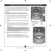
...not want to uninstall it now. WARNING: Use only the light fixture supplied with an integrated light fixture assembly and an optional switch housing cap and plug button. 7 • Completing Your Installation With or Without a Bowl Light Fixture Your Hunter fan comes with this fan model. 7-1. To attach the upper switch housing, partially install two housing assembly screws into the housing. Install the remaining screw into the switch housing mounting plate. 7-2. Steps 7-1 - 7-3 Housing Assembly Screw Upper Switch Housing 12 42450-01 • 11/18/10 • Hunter Fan Company
...not want to uninstall it now. WARNING: Use only the light fixture supplied with an integrated light fixture assembly and an optional switch housing cap and plug button. 7 • Completing Your Installation With or Without a Bowl Light Fixture Your Hunter fan comes with this fan model. 7-1. To attach the upper switch housing, partially install two housing assembly screws into the housing. Install the remaining screw into the switch housing mounting plate. 7-2. Steps 7-1 - 7-3 Housing Assembly Screw Upper Switch Housing 12 42450-01 • 11/18/10 • Hunter Fan Company
Owner's Manual
Page 13
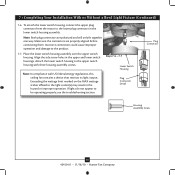
... the lower plug connector in the lower switch housing assembly. Note: In compliance with three housing assembly screws. Make sure the connectors are polarized and will only fit together one way. Steps 7-6 - 7-7 Lower Switch Housing Plug Connector Detail Plug Connector Housing Assembly Screw 13 42450-01 • 11/18/10 • Hunter Fan Company To attach the lower switch housing, connect the upper plug connector from the motor to the product. 7-7. Align the side screw holes in fire hazard or improper operation. Exceeding the wattage limit marked...
... the lower plug connector in the lower switch housing assembly. Note: In compliance with three housing assembly screws. Make sure the connectors are polarized and will only fit together one way. Steps 7-6 - 7-7 Lower Switch Housing Plug Connector Detail Plug Connector Housing Assembly Screw 13 42450-01 • 11/18/10 • Hunter Fan Company To attach the lower switch housing, connect the upper plug connector from the motor to the product. 7-7. Align the side screw holes in fire hazard or improper operation. Exceeding the wattage limit marked...

Owner's Manual
Page 14
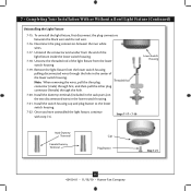
Place the cover plate up against the glass bowl. 7 • Completing Your Installation With or Without a Bowl Light Fixture (Continued) Installing the Glass Bowl 7-8. Light Bulbs (B10 Candelabra Base 60 Watt Maximum) Metal Rod Metal Disk Breakaway Connector Glass Bowl Cover Plate Finial 14 42450-01 • 11/18/10 • Hunter Fan Company Then, thread the fan pull chain through the hole in the center of the glass bowl. 7-11. Then, Thread the light pull chain throught the hole in the center...
Place the cover plate up against the glass bowl. 7 • Completing Your Installation With or Without a Bowl Light Fixture (Continued) Installing the Glass Bowl 7-8. Light Bulbs (B10 Candelabra Base 60 Watt Maximum) Metal Rod Metal Disk Breakaway Connector Glass Bowl Cover Plate Finial 14 42450-01 • 11/18/10 • Hunter Fan Company Then, thread the fan pull chain through the hole in the center of the glass bowl. 7-11. Then, Thread the light pull chain throught the hole in the center...
Owner's Manual
Page 15
.../18/10 • Hunter Fan Company Remove the light fixture from the lower switch housing. 7-19. Once you have uninstalled the light fixture, continue with step 7‑6. 7 • Completing Your Installation With or Without a Bowl Light Fixture (Continued) Uninstalling the Light Fixture 7-15. Install the switch housing cap and plug button to the lower switch housing. 7-22. To uninstall the light fixture, first disconnect the plug connectors between the two white wires. 7-17. Disconnect the plug connectors between the black wire and the red wire. 7-16.
.../18/10 • Hunter Fan Company Remove the light fixture from the lower switch housing. 7-19. Once you have uninstalled the light fixture, continue with step 7‑6. 7 • Completing Your Installation With or Without a Bowl Light Fixture (Continued) Uninstalling the Light Fixture 7-15. Install the switch housing cap and plug button to the lower switch housing. 7-22. To uninstall the light fixture, first disconnect the plug connectors between the two white wires. 7-17. Disconnect the plug connectors between the black wire and the red wire. 7-16.
Owner's Manual
Page 16
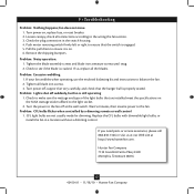
...; Operating and Cleaning Your Ceiling Fan 8-1. The fan pull chain controls power to prevent scratching. Reversing Switch 16 42450-01 • 11/18/10 • Hunter Fan Company In winter, having the fan draw air upward (clockwise blade rotation) will damage the finish. 8-6. Clean wood finish blades with a direct breeze. Restart fan. For cleaning finishes, use upward air flow pattern To Change Airflow Direction Turn the fan off and let it come to the light fixture. The pull chain has four settings in...
...; Operating and Cleaning Your Ceiling Fan 8-1. The fan pull chain controls power to prevent scratching. Reversing Switch 16 42450-01 • 11/18/10 • Hunter Fan Company In winter, having the fan draw air upward (clockwise blade rotation) will damage the finish. 8-6. Clean wood finish blades with a direct breeze. Restart fan. For cleaning finishes, use upward air flow pattern To Change Airflow Direction Turn the fan off and let it come to the light fixture. The pull chain has four settings in...
Owner's Manual
Page 17
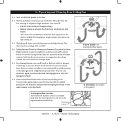
... the hanger ball is still operating 1. Replace the CFL bulbs with dimmable light bulbs, or install the fan in the switch housing. 4. Check to the fan. If your fan wobbles when operating, use the enclosed balancing kit and instructions to make sure the wattage and type of the light bulbs that are not usually made for dimming. Check to balance the fan. 2. Tighten all blade iron screws. 3. Problem: CFL bulbs flicker when controlled by a dimming remote or wall control 1. 9 • Troubleshooting Problem: Nothing happens; fan...
... the hanger ball is still operating 1. Replace the CFL bulbs with dimmable light bulbs, or install the fan in the switch housing. 4. Check to the fan. If your fan wobbles when operating, use the enclosed balancing kit and instructions to make sure the wattage and type of the light bulbs that are not usually made for dimming. Check to balance the fan. 2. Tighten all blade iron screws. 3. Problem: CFL bulbs flicker when controlled by a dimming remote or wall control 1. 9 • Troubleshooting Problem: Nothing happens; fan...
Parts Guide
Page 1
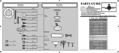
...169;2010 Parts List Item Name Hanger Bracket Assembly Ceiling Plate Canopy Hanger Ball / Downrod Assembly Flat Washer Mounting Isolator Low Profile Washer Canopy Screw Low Profile Screw Wood Screw Wood Screw Setscrew Blade Iron Set Blade Set Switch Housing Assembly Light Kit Assembly Hardware Kit Screw, Blade Iron Armature Blade Grommet Blade Assembly Screw Screw, Machine, 6-32 Wire Connector Screw, Switch Housing Assembly Balancing Kit Pull Chain Bottom Cap Finial Globe/Shade Switch Housing Cover Switch Housing Plug Button Dummy Terminal, Male Dummy Terminal, Female Light bulb / Bulb Model...
...169;2010 Parts List Item Name Hanger Bracket Assembly Ceiling Plate Canopy Hanger Ball / Downrod Assembly Flat Washer Mounting Isolator Low Profile Washer Canopy Screw Low Profile Screw Wood Screw Wood Screw Setscrew Blade Iron Set Blade Set Switch Housing Assembly Light Kit Assembly Hardware Kit Screw, Blade Iron Armature Blade Grommet Blade Assembly Screw Screw, Machine, 6-32 Wire Connector Screw, Switch Housing Assembly Balancing Kit Pull Chain Bottom Cap Finial Globe/Shade Switch Housing Cover Switch Housing Plug Button Dummy Terminal, Male Dummy Terminal, Female Light bulb / Bulb Model...


