Installation Guide
Page 1
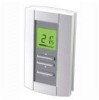
... three outputs for typical wiring diagrams. 4. See section 2.2 for terminal designations and section 3 for the following table for the description of the thermostat up to the particular model of thermostat. contact). See sec- 11 C-Over tion 5.5.2. 9 COM 12 NSB Night Setback activation input (N.O. See section 5.6. TB6980/TB7980 1. Installation Configuration and status display Cooling mode Temperature adjustment button Override button Heating mode Temperature display Output power display 2.1 Mounting Instructions 1. Pass the wires through the center...
... three outputs for typical wiring diagrams. 4. See section 2.2 for terminal designations and section 3 for the following table for the description of the thermostat up to the particular model of thermostat. contact). See sec- 11 C-Over tion 5.5.2. 9 COM 12 NSB Night Setback activation input (N.O. See section 5.6. TB6980/TB7980 1. Installation Configuration and status display Cooling mode Temperature adjustment button Override button Heating mode Temperature display Output power display 2.1 Mounting Instructions 1. Pass the wires through the center...

Installation Guide
Page 2
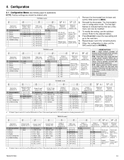
... central cooling TB7980B FIGURE 4: Temperature control of fresh air supply TB7980B CAUTION Do not connect common to ground CAUTION Do not connect common to ground FIGURE 5: Changeover and NSB inputs sharing the same 24-Vac transformer FIGURE 6: Changeover and NSB inputs using different 24-Vac transformers TB6980/TB7980 2/6 TB7980B FIGURE 2: Damper control with electric reheat and auxiliary hot-water heating TB6980B...
... central cooling TB7980B FIGURE 4: Temperature control of fresh air supply TB7980B CAUTION Do not connect common to ground CAUTION Do not connect common to ground FIGURE 5: Changeover and NSB inputs sharing the same 24-Vac transformer FIGURE 6: Changeover and NSB inputs using different 24-Vac transformers TB6980/TB7980 2/6 TB7980B FIGURE 2: Damper control with electric reheat and auxiliary hot-water heating TB6980B...
Installation Guide
Page 3
... new setting and go to the adjacent tables. (35°C) and ''minimum setpoint + 1'' (10°C) and ''maximum setpoint - 1'' 4. Repeat steps 3 and 4 for explanations) NOTE: Factory settings are a quiet alternative to Triac. If used with fast cycling electric heaters, SSR's are inside the shaded cells. Normally open TB7980B model Application (section 4.2) 0 Internal sensor 1 Room 2 Return 3 Supply 4 Auto changeover 5 Limited cooling Default mode & Output 1 type (section 4.3.1) 0 Cool / 0-10V 1 Heat...
... new setting and go to the adjacent tables. (35°C) and ''minimum setpoint + 1'' (10°C) and ''maximum setpoint - 1'' 4. Repeat steps 3 and 4 for explanations) NOTE: Factory settings are a quiet alternative to Triac. If used with fast cycling electric heaters, SSR's are inside the shaded cells. Normally open TB7980B model Application (section 4.2) 0 Internal sensor 1 Room 2 Return 3 Supply 4 Auto changeover 5 Limited cooling Default mode & Output 1 type (section 4.3.1) 0 Cool / 0-10V 1 Heat...
Installation Guide
Page 4
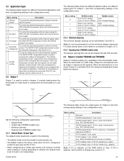
... sensor To control the ambient temperature using the 50014157-001 temperature sensor (the internal sensor is not used to heat or cool respectively. The following table shows the different default modes, the different output types for Output 1, and their corresponding settings in the configuration menu. Menu setting 0 1 2 3 4 5 6 7 8 Description Not used ) 4 Automatic changeover To control the ambient temperature using the 50014157-001 temperature sensor (the internal sensor is set the SW6 switch to allow cool air in the configuration menu. cycle...
... sensor To control the ambient temperature using the 50014157-001 temperature sensor (the internal sensor is not used to heat or cool respectively. The following table shows the different default modes, the different output types for Output 1, and their corresponding settings in the configuration menu. Menu setting 0 1 2 3 4 5 6 7 8 Description Not used ) 4 Automatic changeover To control the ambient temperature using the 50014157-001 temperature sensor (the internal sensor is set the SW6 switch to allow cool air in the configuration menu. cycle...
Installation Guide
Page 5
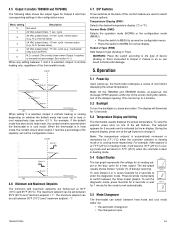
... mode has been set to cooling mode respectively. Note: On the TB6980A and TB6980B models, at power-up , the thermostat undergoes a series of the damper opening ). For example, if the setpoint is at the top of the screen during the calibration of test before displaying the actual temperature. Access Mode (SW2) Selects the operation mode (NORM) or the configuration mode (MENU). • Place the switch to MENU to access the configuration menu...
... mode has been set to cooling mode respectively. Note: On the TB6980A and TB6980B models, at power-up , the thermostat undergoes a series of the damper opening ). For example, if the setpoint is at the top of the screen during the calibration of test before displaying the actual temperature. Access Mode (SW2) Selects the operation mode (NORM) or the configuration mode (MENU). • Place the switch to MENU to access the configuration menu...
Installation Guide
Page 6
... cool mode, it switches to repair or replace the product within the terms stated above limitation may have any time during the warranty period the product is displayed. 5.7 Error Codes The following address: Honeywell Return Goods, Dock 4 MN10-3860, 1885 Douglas Dr N, Golden Valley, MN 55422, or whether a replacement product can appear at 1-800-468-1502. directly to heat mode when the air supply is set via the configuration menu...
... cool mode, it switches to repair or replace the product within the terms stated above limitation may have any time during the warranty period the product is displayed. 5.7 Error Codes The following address: Honeywell Return Goods, Dock 4 MN10-3860, 1885 Douglas Dr N, Golden Valley, MN 55422, or whether a replacement product can appear at 1-800-468-1502. directly to heat mode when the air supply is set via the configuration menu...

