Installation Instructions
Page 1
...Electronic Thermostats INSTALLATION INSTRUCTIONS The T8400C and T8401C Thermostats provide singlestage, non-programmable temperature control for your application. 3. The T8400C Thermostat is powered through the entrance hole on the wallplate. 3. Check the ratings given in the instructions and on the wall. 2. See Fig. 1. Do not install the thermostat...Hazard. Registered Trademark Copyright © 2004 Honeywell International Inc. • • All Rights Reserved 69-1740 concealed pipes and chimneys. - hot or cold air from heat to prevent drafts from the sun or...
...Electronic Thermostats INSTALLATION INSTRUCTIONS The T8400C and T8401C Thermostats provide singlestage, non-programmable temperature control for your application. 3. The T8400C Thermostat is powered through the entrance hole on the wallplate. 3. Check the ratings given in the instructions and on the wall. 2. See Fig. 1. Do not install the thermostat...Hazard. Registered Trademark Copyright © 2004 Honeywell International Inc. • • All Rights Reserved 69-1740 concealed pipes and chimneys. - hot or cold air from heat to prevent drafts from the sun or...
Installation Instructions
Page 3
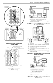
...MEANS AND OVERLOAD PROTECTION AS REQUIRED. 2 CAN BE USED FOR CHANGEOVER VALVE ON SINGLE-STAGE HEAT PUMP SYSTEMS. 3 FACTORY INSTALLED JUMPER. 4 FIELD INSTALLED JUMPER. M20880 Fig. 8. Typical hookup of T8400C in heat-cool system with single transformer. M13275 Fig. 6. G Rc R 24 W B Y ... Fig. 7. G Rc 3 R W 4 Y 2 HEAT CHANGEOVER B 2 COOL O CHANGEOVER 1 L1 (HOT) 24V L2 TRANSFORMER COMPRESSOR FAN RELAY 1 POWER SUPPLY. Typical hookup of T8400C in heat-cool system with two transformers. T8400C, T8401C ELECTRONIC THERMOSTATS KEEP WIRING IN SHADED AREA G Rc R W B Y...
...MEANS AND OVERLOAD PROTECTION AS REQUIRED. 2 CAN BE USED FOR CHANGEOVER VALVE ON SINGLE-STAGE HEAT PUMP SYSTEMS. 3 FACTORY INSTALLED JUMPER. 4 FIELD INSTALLED JUMPER. M20880 Fig. 8. Typical hookup of T8400C in heat-cool system with single transformer. M13275 Fig. 6. G Rc R 24 W B Y ... Fig. 7. G Rc 3 R W 4 Y 2 HEAT CHANGEOVER B 2 COOL O CHANGEOVER 1 L1 (HOT) 24V L2 TRANSFORMER COMPRESSOR FAN RELAY 1 POWER SUPPLY. Typical hookup of T8400C in heat-cool system with two transformers. T8400C, T8401C ELECTRONIC THERMOSTATS KEEP WIRING IN SHADED AREA G Rc R W B Y...
Installation Instructions
Page 4
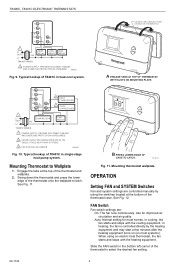
... CHANGEOVER VALVE ON SINGLE-STAGE HEAT PUMP SYSTEMS. 3 FIELD INSTALLED JUMPER. OPERATION Setting FAN and SYSTEM Switches Fan and system settings are : On: The fan runs continuously. Engage the tabs at the bottom of the thermostat to latch. DASHED LINES INDICATE... TABS ON BACK OF THERMOSTAT Set Room AuFtoANOn CoSoYl SOTffEMHeat A ENGAGE TABS AT TOP OF THERMOSTAT WITH SLOTS ON MOUNTING PLATE. M20882 Fig. 10. T8400C, T8401C ELECTRONIC THERMOSTATS G C R W B Y O 1 L1 (HOT) 24V L2 TRANSFORMER HEAT RELAY COOL ...
... CHANGEOVER VALVE ON SINGLE-STAGE HEAT PUMP SYSTEMS. 3 FIELD INSTALLED JUMPER. OPERATION Setting FAN and SYSTEM Switches Fan and system settings are : On: The fan runs continuously. Engage the tabs at the bottom of the thermostat to latch. DASHED LINES INDICATE... TABS ON BACK OF THERMOSTAT Set Room AuFtoANOn CoSoYl SOTffEMHeat A ENGAGE TABS AT TOP OF THERMOSTAT WITH SLOTS ON MOUNTING PLATE. M20882 Fig. 10. T8400C, T8401C ELECTRONIC THERMOSTATS G C R W B Y O 1 L1 (HOT) 24V L2 TRANSFORMER HEAT RELAY COOL ...
Installation Instructions
Page 5
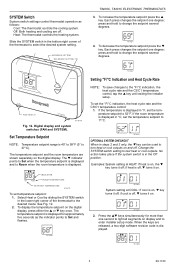
... the SYSTEM switch setting to the °F/°C indication, the heat cycle rate and the C3/C1 temperature control, tap the ▲ key until exiting the installer setup. M14684 System setting at HEAT: If heat is displayed for more than one degree; if cool is on,...INCREASE SETTING DECREASE SETTING T8400C, T8401C ELECTRONIC THERMOSTATS 3. press and hold to change the setpoint several degrees. M14681 4. M14680 Setting °F/°C Indication and Heat Cycle Rate NOTE: To save changes to test heat or cool outputs. Off: Both heating and cooling are shown separately on ...
... the SYSTEM switch setting to the °F/°C indication, the heat cycle rate and the C3/C1 temperature control, tap the ▲ key until exiting the installer setup. M14684 System setting at HEAT: If heat is displayed for more than one degree; if cool is on,...INCREASE SETTING DECREASE SETTING T8400C, T8401C ELECTRONIC THERMOSTATS 3. press and hold to change the setpoint several degrees. M14681 4. M14680 Setting °F/°C Indication and Heat Cycle Rate NOTE: To save changes to test heat or cool outputs. Off: Both heating and cooling are shown separately on ...
Installation Instructions
Page 6
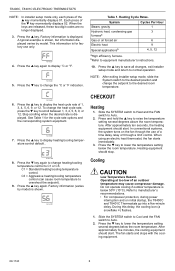
... only. During this delay, the cooling icon (a snowflake ❄) flashes. 1. M14687 4. M18419A 8. After approximately ten seconds, the heating equipment should stop. bRefer to Auto. 2. Press the ▲ key again. T8400C, T8401C ELECTRONIC THERMOSTATS NOTE: In installer setup mode only, each press of the ▼ key momentarily displays 02. This information is shown, but information...
... only. During this delay, the cooling icon (a snowflake ❄) flashes. 1. M14687 4. M18419A 8. After approximately ten seconds, the heating equipment should stop. bRefer to Auto. 2. Press the ▲ key again. T8400C, T8401C ELECTRONIC THERMOSTATS NOTE: In installer setup mode only, each press of the ▼ key momentarily displays 02. This information is shown, but information...


