Installation Instructions
Page 1
...thermostat, wallplate (for operation. CAUTION Electrical Shock or Equipment Damage Hazard. radiant heat from ducts. - Handle it can be a trained, experienced service technician. 4. Mount the T8400C and T8401C with the screws provided (see Wiring section. ® U.S. Registered Trademark Copyright © 2004 Honeywell...damage the product or cause a hazardous condition. 2. T8400C, T8401C Electronic Thermostats INSTALLATION INSTRUCTIONS The T8400C and T8401C Thermostats provide singlestage, non-programmable temperature control for your application. 3. Disconnect power...
...thermostat, wallplate (for operation. CAUTION Electrical Shock or Equipment Damage Hazard. radiant heat from ducts. - Handle it can be a trained, experienced service technician. 4. Mount the T8400C and T8401C with the screws provided (see Wiring section. ® U.S. Registered Trademark Copyright © 2004 Honeywell...damage the product or cause a hazardous condition. 2. T8400C, T8401C Electronic Thermostats INSTALLATION INSTRUCTIONS The T8400C and T8401C Thermostats provide singlestage, non-programmable temperature control for your application. 3. Disconnect power...
Installation Instructions
Page 2
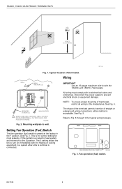
...3/16 INCH HOLES FOR DRYWALL, 7/32 INCH HOLES FOR PLASTER OR WOOD. The E setting allows the fan to the E position. T8400C, T8401C ELECTRONIC THERMOSTATS YES NO NO 5 FEET [1.5 METERS] NO M11338 Fig. 1. This is the correct setting for typical wiring hookups. Wiring WALL 1 WALL ANCHORS ... electrical shock or equipment damage. Disconnect the power supply to wire the T8400C and T8401C Thermostats. NOTE: To ensure proper mounting of thermostat. either method is an electric heat system, set the switch to turn on immediately with local electrical codes and ordinances. Typical...
...3/16 INCH HOLES FOR DRYWALL, 7/32 INCH HOLES FOR PLASTER OR WOOD. The E setting allows the fan to the E position. T8400C, T8401C ELECTRONIC THERMOSTATS YES NO NO 5 FEET [1.5 METERS] NO M11338 Fig. 1. This is the correct setting for typical wiring hookups. Wiring WALL 1 WALL ANCHORS ... electrical shock or equipment damage. Disconnect the power supply to wire the T8400C and T8401C Thermostats. NOTE: To ensure proper mounting of thermostat. either method is an electric heat system, set the switch to turn on immediately with local electrical codes and ordinances. Typical...
Installation Instructions
Page 3
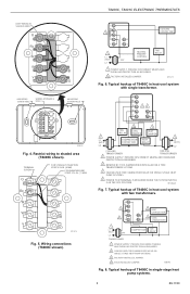
... CONTROL FAN RELAY 1 POWER SUPPLY. Typical hookup of T8400C in heat-cool system with two transformers. G Rc 3 R W 4 Y 2 HEAT CHANGEOVER B 2 COOL O CHANGEOVER 1 L1 (HOT) 24V L2 TRANSFORMER COMPRESSOR FAN RELAY 1 POWER SUPPLY. T8400C, T8401C ELECTRONIC THERMOSTATS KEEP WIRING IN SHADED AREA G Rc R W B Y O MOUNTING SCREW HOLE WIRING ENTRANCE HOLE MOUNTING SCREW HOLE M16432 Fig. 4. PROVIDE DISCONNECT...
... CONTROL FAN RELAY 1 POWER SUPPLY. Typical hookup of T8400C in heat-cool system with two transformers. G Rc 3 R W 4 Y 2 HEAT CHANGEOVER B 2 COOL O CHANGEOVER 1 L1 (HOT) 24V L2 TRANSFORMER COMPRESSOR FAN RELAY 1 POWER SUPPLY. T8400C, T8401C ELECTRONIC THERMOSTATS KEEP WIRING IN SHADED AREA G Rc R W B Y O MOUNTING SCREW HOLE WIRING ENTRANCE HOLE MOUNTING SCREW HOLE M16432 Fig. 4. PROVIDE DISCONNECT...
Installation Instructions
Page 4
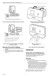
... 1 POWER SUPPLY. Typical hookup of the thermostat onto the wallplate to Wallplate 1. OPERATION Setting FAN and SYSTEM Switches Fan and system settings are : On: The fan runs continuously. PROVIDE DISCONNECT MEANS AND OVERLOAD PROTECTION AS REQUIRED. M20881 Fig. 9. T8400C, T8401C ELECTRONIC THERMOSTATS G C R W B Y O 1 L1 (HOT) 24V L2 TRANSFORMER HEAT RELAY COOL RELAY FAN RELAY 1 POWER...
... 1 POWER SUPPLY. Typical hookup of the thermostat onto the wallplate to Wallplate 1. OPERATION Setting FAN and SYSTEM Switches Fan and system settings are : On: The fan runs continuously. PROVIDE DISCONNECT MEANS AND OVERLOAD PROTECTION AS REQUIRED. M20881 Fig. 9. T8400C, T8401C ELECTRONIC THERMOSTATS G C R W B Y O 1 L1 (HOT) 24V L2 TRANSFORMER HEAT RELAY COOL RELAY FAN RELAY 1 POWER...
Installation Instructions
Page 5
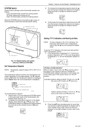
... 11°C. INCREASE SETTING DECREASE SETTING T8400C, T8401C ELECTRONIC THERMOSTATS 3. Change the SYSTEM switch setting to the °F/°C indication, the heat cycle rate and the C3/C1 temperature control, tap the ▲ key until exiting the installer setup. Heat: The thermostat controls the heating system. To increase the temperature setpoint press the ▲ key. Each...
... 11°C. INCREASE SETTING DECREASE SETTING T8400C, T8401C ELECTRONIC THERMOSTATS 3. Change the SYSTEM switch setting to the °F/°C indication, the heat cycle rate and the C3/C1 temperature control, tap the ▲ key until exiting the installer setup. Heat: The thermostat controls the heating system. To increase the temperature setpoint press the ▲ key. Each...
Installation Instructions
Page 6
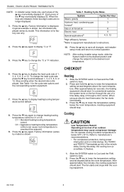
...8226; For compressor protection, during power interruption and on the fan through the use only. When using an electric heat thermostat, the fan starts immediately. 3. Do not operate cooling if outdoor temperature is for the cycle rate options and the corresponding ... change heating/cooling temperature control to equipment manufacturer's instructions. 10. M14689 6. Press the ▲ key to display °C or °F. Operating at too low of 1, 3, 4, 5, 6, 9, or 12. bRefer to C1 or C3. Cooling CAUTION Low Temperature Hazard. T8400C, T8401C ELECTRONIC THERMOSTATS NOTE:...
...8226; For compressor protection, during power interruption and on the fan through the use only. When using an electric heat thermostat, the fan starts immediately. 3. Do not operate cooling if outdoor temperature is for the cycle rate options and the corresponding ... change heating/cooling temperature control to equipment manufacturer's instructions. 10. M14689 6. Press the ▲ key to display °C or °F. Operating at too low of 1, 3, 4, 5, 6, 9, or 12. bRefer to C1 or C3. Cooling CAUTION Low Temperature Hazard. T8400C, T8401C ELECTRONIC THERMOSTATS NOTE:...
Installation Instructions
Page 7
...: To bypass the five-minute delay, see the Optional System Checkout section. T8400C, T8401C ELECTRONIC THERMOSTATS Fan 1. The fan should shut down. 3. In cooling, the fan starts and stops with the heating equipment. Slide the FAN switch to the thermostat. 7 69-1740 Be sure all equipment responds correctly to Auto. Press the ▲ key...
...: To bypass the five-minute delay, see the Optional System Checkout section. T8400C, T8401C ELECTRONIC THERMOSTATS Fan 1. The fan should shut down. 3. In cooling, the fan starts and stops with the heating equipment. Slide the FAN switch to the thermostat. 7 69-1740 Be sure all equipment responds correctly to Auto. Press the ▲ key...


