User Guide
Page 2
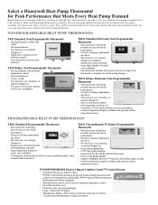
...; Microelectronic technology provides precise zero-droop performance. • Attractive styling complements any décor. • Two heat/one cool; Select a Honeywell Heat Pump Thermostat for Peak Performance that Meets Every Heat Pump Demand Rapid advances in heat pump technology, resulting in living space and accurately measures and controls room temperature and humidity. manual changeover eliminates unexpected system...
...; Microelectronic technology provides precise zero-droop performance. • Attractive styling complements any décor. • Two heat/one cool; Select a Honeywell Heat Pump Thermostat for Peak Performance that Meets Every Heat Pump Demand Rapid advances in heat pump technology, resulting in living space and accurately measures and controls room temperature and humidity. manual changeover eliminates unexpected system...
User Guide
Page 4
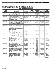
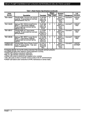
... Heat Pump Thermostat Model Specifications Table 1. W2,Y,G,R, O,B,L,E,X Replaces T841A1068 and T841A1407, T841A1530, GE AY28Y078 and AY28Y139. for two-stage heating and one -stage cooling. Auto fan in EM. W2,W3,Y,G, B,O,R,X,E For "No Emergency Heat" applications. With outdoor reset; No auto fan in EM. HT. (Fig. 22). Includes T874G1741/Q674F1477. includes T874G1972/ Q674F1584. W1,W2,W3, G,Y,R,O,B, E,X,X2,L Stages Systems Heat Cool...
... Heat Pump Thermostat Model Specifications Table 1. W2,Y,G,R, O,B,L,E,X Replaces T841A1068 and T841A1407, T841A1530, GE AY28Y078 and AY28Y139. for two-stage heating and one -stage cooling. Auto fan in EM. W2,W3,Y,G, B,O,R,X,E For "No Emergency Heat" applications. With outdoor reset; No auto fan in EM. HT. (Fig. 22). Includes T874G1741/Q674F1477. includes T874G1972/ Q674F1584. W1,W2,W3, G,Y,R,O,B, E,X,X2,L Stages Systems Heat Cool...
User Guide
Page 5
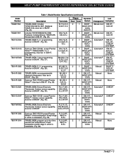
... T8611R1000 T8411R1002 T8411R1028 T8511G1021 T8511G1047 T8511M1002 T8011R1006 T8011R1014 Table 1. Auto fan in EM.HT. (Fig. 23). Automatica EM.HT., HEAT-OFF- includes T874R1954/Q674L1827. TRADELINE®; 7 day programming. TRADELINE®; 5-1-1 programming. Description Terminals Stages Systems Led Heat Cool Switch Changeover Indication TRADELINE®; Automatica EM.HT., HEAT-OFF- non-programmable electronic thermostat. E,L,OT,OT TRADELINE®;
... T8611R1000 T8411R1002 T8411R1028 T8511G1021 T8511G1047 T8511M1002 T8011R1006 T8011R1014 Table 1. Auto fan in EM.HT. (Fig. 23). Automatica EM.HT., HEAT-OFF- includes T874R1954/Q674L1827. TRADELINE®; 7 day programming. TRADELINE®; 5-1-1 programming. Description Terminals Stages Systems Led Heat Cool Switch Changeover Indication TRADELINE®; Automatica EM.HT., HEAT-OFF- non-programmable electronic thermostat. E,L,OT,OT TRADELINE®;
User Guide
Page 6
...Terminals Stages Systems Heat Cool Switch Changeover T8611G2002 TRADELINE®; W3,G,E,L,R, Programmable fan and back lighting O/B,C,X1, features. c CHECK LED indicates compressor malfunction. HT. Full seven-day program Y1,W1,W2, 2 capability. COOL T8611G2028 Same as T8611M2017 except Premier ...OT,OT 1 EM.HT.- g CHECK LED lights to alert homeowner to the L terminal. AUTO- Automatica HEAT-OFF- HEAT PUMP THERMOSTAT CROSS REFERENCE/SELECTION GUIDE Table 1. Programmable fan and back G,E,L,R,C, lighting features. (Fig. 31). full 7-day program Y1,Y2/...
...Terminals Stages Systems Heat Cool Switch Changeover T8611G2002 TRADELINE®; W3,G,E,L,R, Programmable fan and back lighting O/B,C,X1, features. c CHECK LED indicates compressor malfunction. HT. Full seven-day program Y1,W1,W2, 2 capability. COOL T8611G2028 Same as T8611M2017 except Premier ...OT,OT 1 EM.HT.- g CHECK LED lights to alert homeowner to the L terminal. AUTO- Automatica HEAT-OFF- HEAT PUMP THERMOSTAT CROSS REFERENCE/SELECTION GUIDE Table 1. Programmable fan and back G,E,L,R,C, lighting features. (Fig. 31). full 7-day program Y1,Y2/...
User Guide
Page 7
... Thermostats T8411 Electronic Heat Pump Thermostats The T8411 models control two-stage heat and one -stage cool in memory (no batteries required) and retained during power failures. Electronic thermostats provide droopless temperature control. 70-6627 • 5 cooling anticipator is selectable at 3, 6, or 9 cph. Heat anticipators are either adjustable or fixed; cooling anticipator is fixed; It takes more frequent. NOTE: All Honeywell electronic heat...
... Thermostats T8411 Electronic Heat Pump Thermostats The T8411 models control two-stage heat and one -stage cool in memory (no batteries required) and retained during power failures. Electronic thermostats provide droopless temperature control. 70-6627 • 5 cooling anticipator is selectable at 3, 6, or 9 cph. Heat anticipators are either adjustable or fixed; cooling anticipator is fixed; It takes more frequent. NOTE: All Honeywell electronic heat...
User Guide
Page 8
...; 6 Electronic Programmable Heat Pump Thermostats T8011 Standard Electronic Heat Pump Thermostats The T8011 models provide two-stage heat and one -stage cool in heat pump systems, using manual or automatic changeover. Connect all other terminals as the differential required between stage 1 and stage 2 in multistage equipment is wired to two-speed heat pump equipment: 1. First stage heat anticipation is a three-stage heat/two-stage cool thermostat used to the...
...; 6 Electronic Programmable Heat Pump Thermostats T8011 Standard Electronic Heat Pump Thermostats The T8011 models provide two-stage heat and one -stage cool in heat pump systems, using manual or automatic changeover. Connect all other terminals as the differential required between stage 1 and stage 2 in multistage equipment is wired to two-speed heat pump equipment: 1. First stage heat anticipation is a three-stage heat/two-stage cool thermostat used to the...
User Guide
Page 9
...174; IV Thermostats with Adaptive Intelligent Recovery™ control. When the system switch is in the COOL position, the O terminal is selectable. Adaptive Intelligent Recovery™ control assures that provide changeover in the cooling model. Honeywell does not ...thermostat calls for heat, the thermostat Y terminal activates the first stage of cooling. 70-6627 • 7 Now when the thermostat calls for stage 1 heat and stage 1 cool. The Y terminal is connected to three-stage heat and two-stage cool control for the T8611G or T8611M to the installation. second stage heat...
...174; IV Thermostats with Adaptive Intelligent Recovery™ control. When the system switch is in the COOL position, the O terminal is selectable. Adaptive Intelligent Recovery™ control assures that provide changeover in the cooling model. Honeywell does not ...thermostat calls for heat, the thermostat Y terminal activates the first stage of cooling. 70-6627 • 7 Now when the thermostat calls for stage 1 heat and stage 1 cool. The Y terminal is connected to three-stage heat and two-stage cool control for the T8611G or T8611M to the installation. second stage heat...
User Guide
Page 10
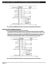
... contacts on the R8222B Switching Relay. Equipment Function Power 1st Stage Cool 2nd Stage Cool Fan 1st Stage Heat 2nd Stage Heat Transformer Common Equipment Terminals R Y1 Y2 G W1 W2 C T8611M Terminals R Y2 G W2 C Y Cooling Changeover O B R8222B Relay O M13230 Fig. 3. Now when the thermostat calls for cooling, the thermostat Y terminal activates the first stage of the Chronotherm® III T8611G and T8611M Y terminal...
... contacts on the R8222B Switching Relay. Equipment Function Power 1st Stage Cool 2nd Stage Cool Fan 1st Stage Heat 2nd Stage Heat Transformer Common Equipment Terminals R Y1 Y2 G W1 W2 C T8611M Terminals R Y2 G W2 C Y Cooling Changeover O B R8222B Relay O M13230 Fig. 3. Now when the thermostat calls for cooling, the thermostat Y terminal activates the first stage of the Chronotherm® III T8611G and T8611M Y terminal...
User Guide
Page 11
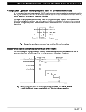
... Equipment Function Terminal Designation Transformer Common C 1st Stage Cooling Y1 1st Stage Heating W1 New Terminal Designation C Y O M13235 Fig. 5. Require relay (R8222B1067 typically) for Carrier equipment (typical 38BQ), and T8511M, T8611M, PC8900/W8900B1002. HEAT PUMP THERMOSTAT CROSS REFERENCE/SELECTION GUIDE Changing Fan Operation in Emergency Heat Mode for Electronic Thermostats In the emergency heat mode (system switch in emergency...
... Equipment Function Terminal Designation Transformer Common C 1st Stage Cooling Y1 1st Stage Heating W1 New Terminal Designation C Y O M13235 Fig. 5. Require relay (R8222B1067 typically) for Carrier equipment (typical 38BQ), and T8511M, T8611M, PC8900/W8900B1002. HEAT PUMP THERMOSTAT CROSS REFERENCE/SELECTION GUIDE Changing Fan Operation in Emergency Heat Mode for Electronic Thermostats In the emergency heat mode (system switch in emergency...
User Guide
Page 14
... Heat E E 2nd Stage Cooling Y2 Y2 M13234 Fig. 13. Emergency Heat E E 2nd Stage Cooling Y2 Y2 M13233 Fig. 12. Equipment Equipment Function Terminals Transformer Common C Power R Fan G 1st Stage Cooling Y1 1st Stage Heating W1 Changeover Valve O PC8900 Terminals C R G O/B Y1/W1 2nd Stage Heating W2 Aux. HEAT PUMP THERMOSTAT CROSS REFERENCE/SELECTION GUIDE Equipment Equipment Function Terminals Transformer Common C Power R Fan G 1st Stage Heating W1 1st Stage Cooling...
... Heat E E 2nd Stage Cooling Y2 Y2 M13234 Fig. 13. Emergency Heat E E 2nd Stage Cooling Y2 Y2 M13233 Fig. 12. Equipment Equipment Function Terminals Transformer Common C Power R Fan G 1st Stage Cooling Y1 1st Stage Heating W1 Changeover Valve O PC8900 Terminals C R G O/B Y1/W1 2nd Stage Heating W2 Aux. HEAT PUMP THERMOSTAT CROSS REFERENCE/SELECTION GUIDE Equipment Equipment Function Terminals Transformer Common C Power R Fan G 1st Stage Heating W1 1st Stage Cooling...

User Guide
Page 15
... by moving the system switch to the L terminal on some heat pumps. The system monitor relay may be wired to COOL (manual changeover) or by a mercury switch that makes on a temperature fall (auto changeover). C1-Stage 1 Cooling. All T874 Multistage Thermostats use mercury switches. HEAT switching). HT.-HEAT-OFFCOOL switching). Key to change mode (EX: Q674L with...
... by moving the system switch to the L terminal on some heat pumps. The system monitor relay may be wired to COOL (manual changeover) or by a mercury switch that makes on a temperature fall (auto changeover). C1-Stage 1 Cooling. All T874 Multistage Thermostats use mercury switches. HEAT switching). HT.-HEAT-OFFCOOL switching). Key to change mode (EX: Q674L with...

User Guide
Page 17
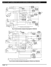
... EM. W2 AUX. Internal schematic and typical wiring diagram for T841A1308. 70-6627 • 15 RELAY SYSTEM MONITOR X LACO Y HEAT CHANGEOVER VALVE COMPRESSOR CONTACTOR O COOL CHANGEOVER VALVE CHP M6060A Fig. 16. HT. HEAT PUMP THERMOSTAT CROSS REFERENCE/SELECTION GUIDE Typical System Hookup Diagrams L1 L2 (HOT) RTD 1 1 ODT 1 H1 C1 FALL H1/C1 ANTICIPATOR...
... EM. W2 AUX. Internal schematic and typical wiring diagram for T841A1308. 70-6627 • 15 RELAY SYSTEM MONITOR X LACO Y HEAT CHANGEOVER VALVE COMPRESSOR CONTACTOR O COOL CHANGEOVER VALVE CHP M6060A Fig. 16. HT. HEAT PUMP THERMOSTAT CROSS REFERENCE/SELECTION GUIDE Typical System Hookup Diagrams L1 L2 (HOT) RTD 1 1 ODT 1 H1 C1 FALL H1/C1 ANTICIPATOR...
User Guide
Page 19
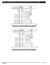
... (RED) F AUX. PROVIDE DISCONNECT MEANS AND OVERLOAD PROTECTION AS REQUIRED. HEAT PUMP THERMOSTAT CROSS REFERENCE/SELECTION GUIDE H1/C1 ANTICIPATOR H1 C1 FALL FAN SWITCH AUTO ON W1 HEAT RELAY 1 W2 HEAT RELAY 2 B HEAT CHANGEOVER VALVE G FAN RELAY H2 ANTICIPATOR H2 FALL SYSTEM SWITCH HEAT OFF COOL 1 POWER SUPPLY. L1 (HOT) L2 1 M1593 70-6627 • 17...
... (RED) F AUX. PROVIDE DISCONNECT MEANS AND OVERLOAD PROTECTION AS REQUIRED. HEAT PUMP THERMOSTAT CROSS REFERENCE/SELECTION GUIDE H1/C1 ANTICIPATOR H1 C1 FALL FAN SWITCH AUTO ON W1 HEAT RELAY 1 W2 HEAT RELAY 2 B HEAT CHANGEOVER VALVE G FAN RELAY H2 ANTICIPATOR H2 FALL SYSTEM SWITCH HEAT OFF COOL 1 POWER SUPPLY. L1 (HOT) L2 1 M1593 70-6627 • 17...
User Guide
Page 20
... CHECK LED (RED) COMPRESSOR FAULT X2 EM. HT. Y1 JUMPER IS Y TERMINAL; HEAT AUTO COOL O COOL CHANGEOVER VALVE G B RELAY FAN RELAY B R E EM. LED (RED) X AUX. HEAT RELAY W2 L1 (HOT) L2 1 Y 1 POWER SUPPLY. HEAT AUTO COOL W2 E AUX. HEAT PUMP THERMOSTAT CROSS REFERENCE/SELECTION GUIDE FALL 1 H1 ANTICIPATOR 2 H1 4 6 H2 ANTICIPATOR H2 FALL RISE 8 C1 9 C1 ANTICIPATOR 10...
... CHECK LED (RED) COMPRESSOR FAULT X2 EM. HT. Y1 JUMPER IS Y TERMINAL; HEAT AUTO COOL O COOL CHANGEOVER VALVE G B RELAY FAN RELAY B R E EM. LED (RED) X AUX. HEAT RELAY W2 L1 (HOT) L2 1 Y 1 POWER SUPPLY. HEAT AUTO COOL W2 E AUX. HEAT PUMP THERMOSTAT CROSS REFERENCE/SELECTION GUIDE FALL 1 H1 ANTICIPATOR 2 H1 4 6 H2 ANTICIPATOR H2 FALL RISE 8 C1 9 C1 ANTICIPATOR 10...
User Guide
Page 21
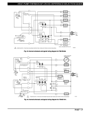
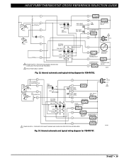
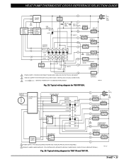
.... AUX. PROVIDE DISCONNECT MEANS AND OVERLOAD PROTECTION AS REQUIRED. Fig. 24. HEAT RELAY W2 FAN RELAY G COOL CHANGEOVER VALVE O COOL E COMPRESSOR EM. HEAT LED (GREEN) EM. HEATER RELAY B COMPRESSOR MONITOR F R 1 L1 (HOT) L2 T X2 OUTDOOR THERMOSTAT O COMPRESSOR CONTACTOR Y OUTDOOR SENSOR COOL CHANGEOVER VALVE M8701 Fig. 23. HEAT LED (RED) X AUX. PROVIDE DISCONNECT MEANS AND OVERLOAD PROTECTION AS...
.... AUX. PROVIDE DISCONNECT MEANS AND OVERLOAD PROTECTION AS REQUIRED. Fig. 24. HEAT RELAY W2 FAN RELAY G COOL CHANGEOVER VALVE O COOL E COMPRESSOR EM. HEAT LED (GREEN) EM. HEATER RELAY B COMPRESSOR MONITOR F R 1 L1 (HOT) L2 T X2 OUTDOOR THERMOSTAT O COMPRESSOR CONTACTOR Y OUTDOOR SENSOR COOL CHANGEOVER VALVE M8701 Fig. 23. HEAT LED (RED) X AUX. PROVIDE DISCONNECT MEANS AND OVERLOAD PROTECTION AS...
User Guide
Page 22
.... RELAY E EM. HT. LED (RED) AUX. LED (GRN) W2 AUX. Internal schematic and typical wiring diagram for Y594R1425. 70-6627 • 20 HEAT OFF COOL 11 1 POWER SUPPLY. HT. HEAT PUMP THERMOSTAT CROSS REFERENCE/SELECTION GUIDE W3 W3 RELAY H1 ANTICIPATOR 1 C ANTICIPATOR 2 FAN SWITCH AUTO ON H1 3 C FALL 4 5 H2 ANTICIPATOR H2 6 FALL SYSTEM SWITCH...
.... RELAY E EM. HT. LED (RED) AUX. LED (GRN) W2 AUX. Internal schematic and typical wiring diagram for Y594R1425. 70-6627 • 20 HEAT OFF COOL 11 1 POWER SUPPLY. HT. HEAT PUMP THERMOSTAT CROSS REFERENCE/SELECTION GUIDE W3 W3 RELAY H1 ANTICIPATOR 1 C ANTICIPATOR 2 FAN SWITCH AUTO ON H1 3 C FALL 4 5 H2 ANTICIPATOR H2 6 FALL SYSTEM SWITCH...
User Guide
Page 23
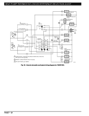
... CIRCUIT SUBBASE LOGIC/ CONTROL CIRCUIT FAN SWITCH ON AUTO HIGH LIMIT EM. RELAY FAN RELAY G SYSTEM SWITCH EM. HEAT OFF AUTO COOL C. PROVIDE DISCONNECT MEANS AND OVERLOAD PROTECTION AS REQUIRED. 2 DENOTES THERMOSTAT TO SUBBASE INTERCONNECT. HT. HT. HT. O. LED (RED) R C/X AUX. Typical wiring diagram for T8611G1004 and T8611G1103. Y X1 3 CHECK LED (YELLOW) X2...
... CIRCUIT SUBBASE LOGIC/ CONTROL CIRCUIT FAN SWITCH ON AUTO HIGH LIMIT EM. RELAY FAN RELAY G SYSTEM SWITCH EM. HEAT OFF AUTO COOL C. PROVIDE DISCONNECT MEANS AND OVERLOAD PROTECTION AS REQUIRED. 2 DENOTES THERMOSTAT TO SUBBASE INTERCONNECT. HT. HT. HT. O. LED (RED) R C/X AUX. Typical wiring diagram for T8611G1004 and T8611G1103. Y X1 3 CHECK LED (YELLOW) X2...

User Guide
Page 24
... C. VALVE O C. HT. ROUTE INTERCONNECT CABLE AWAY FROM SOURCES OF ELECTRICAL NOISE. RELAY W3 HEAT 3 STAGE 2 RELAY W2 HEAT 2 EM. HEAT CHANGEOVER VALVE B STAGE 1 COMPRESSOR CONTACTOR Y STAGE 2 COMPRESSOR CONTACTOR Y2 COOL 2 X1 2 CHECK LED (YELLOW) X2 L1 (HOT) L2 1 1 POWER SUPPLY. Typical wiring ... SYSTEM TRANSFORMER SWITCH IN SECONDARY OF SEPARATE TRANSFORMER 3 SOME OLDER HEAT PUMP THERMOSTATS USE X FOR COMMON TERMINAL. 4 NOMINAL 24 VAC POWER MUST BE PRESENT BETWEEN R AND C TERMINALS FOR THERMOSTAT OPERATIONS. 5 AVAILABLE ONLY ON MODLES WITH SEPARATE SENSOR FOR REMOTE...
... C. VALVE O C. HT. ROUTE INTERCONNECT CABLE AWAY FROM SOURCES OF ELECTRICAL NOISE. RELAY W3 HEAT 3 STAGE 2 RELAY W2 HEAT 2 EM. HEAT CHANGEOVER VALVE B STAGE 1 COMPRESSOR CONTACTOR Y STAGE 2 COMPRESSOR CONTACTOR Y2 COOL 2 X1 2 CHECK LED (YELLOW) X2 L1 (HOT) L2 1 1 POWER SUPPLY. Typical wiring ... SYSTEM TRANSFORMER SWITCH IN SECONDARY OF SEPARATE TRANSFORMER 3 SOME OLDER HEAT PUMP THERMOSTATS USE X FOR COMMON TERMINAL. 4 NOMINAL 24 VAC POWER MUST BE PRESENT BETWEEN R AND C TERMINALS FOR THERMOSTAT OPERATIONS. 5 AVAILABLE ONLY ON MODLES WITH SEPARATE SENSOR FOR REMOTE...
User Guide
Page 25
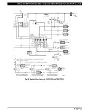
... MEANS AND OVERLOAD PROTECTION AS REQUIRED. 2 REMOVE JUMPER FOR SYSTEM WITH ISOLATED STAGE 1 HEATING AND COOLING CONNECTIONS. 3 DENOTES THERMOSTAT TO SUBBASE INTERCONNECT. HT. RELAY E STAGE 1 HEAT RELAY W1 FAN RELAY G COOL 1 HEAT 1 O 2 COOL CHANGEOVER VALVE B HEAT CHANGEOVER VALVE Y1 COMPRESSOR CONTACTOR P 1 POWER SUPPLY. M11333 Fig. 29. HEAT OFF COOL HIGH LIMIT HIGH LIMIT EM. HT. Typical wiring diagram for T8011R and T8411R...
... MEANS AND OVERLOAD PROTECTION AS REQUIRED. 2 REMOVE JUMPER FOR SYSTEM WITH ISOLATED STAGE 1 HEATING AND COOLING CONNECTIONS. 3 DENOTES THERMOSTAT TO SUBBASE INTERCONNECT. HT. RELAY E STAGE 1 HEAT RELAY W1 FAN RELAY G COOL 1 HEAT 1 O 2 COOL CHANGEOVER VALVE B HEAT CHANGEOVER VALVE Y1 COMPRESSOR CONTACTOR P 1 POWER SUPPLY. M11333 Fig. 29. HEAT OFF COOL HIGH LIMIT HIGH LIMIT EM. HT. Typical wiring diagram for T8011R and T8411R...
User Guide
Page 26
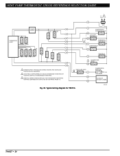
.... 2 O/B IS FIELD CONFIGURABLE TO SELECT ENERGIZED IN HEATING OR COOLING. (DEFAULT IS ENERGIZED IN HEATING). 3 REMOVE JUMPER, WHEN SUPPLIED, FOR SYSTEMS WITH SEPARATE HEATING COMPRESSOR CONTACTOR (W1 SEPARATE FROM Y1). Typical wiring diagram for T8511G. COMPRESSOR MONITOR TO R OUTDOOR SENSOR C7089B M13281 70-6627 • 24 HEAT PUMP THERMOSTAT CROSS REFERENCE/SELECTION GUIDE L1 1 (HOT) L2...
.... 2 O/B IS FIELD CONFIGURABLE TO SELECT ENERGIZED IN HEATING OR COOLING. (DEFAULT IS ENERGIZED IN HEATING). 3 REMOVE JUMPER, WHEN SUPPLIED, FOR SYSTEMS WITH SEPARATE HEATING COMPRESSOR CONTACTOR (W1 SEPARATE FROM Y1). Typical wiring diagram for T8511G. COMPRESSOR MONITOR TO R OUTDOOR SENSOR C7089B M13281 70-6627 • 24 HEAT PUMP THERMOSTAT CROSS REFERENCE/SELECTION GUIDE L1 1 (HOT) L2...


