User Guide
Page 2
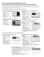
..., continuously lit display. • Simultaneous display of heat and cool setpoints with excellent temperature control. • Electromechanical. • Classic styling. • Two heat/one cool; Y594 Deluxe Non-Programmable Thermostat • Proven reliability with push of comfort available. Honeywell heat pump thermostats are located on the lower edge of heat pump thermostats. manual changeover. • Single-piece construction-no subbase...
..., continuously lit display. • Simultaneous display of heat and cool setpoints with excellent temperature control. • Electromechanical. • Classic styling. • Two heat/one cool; Y594 Deluxe Non-Programmable Thermostat • Proven reliability with push of comfort available. Honeywell heat pump thermostats are located on the lower edge of heat pump thermostats. manual changeover. • Single-piece construction-no subbase...
User Guide
Page 4
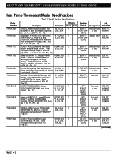
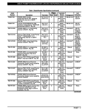
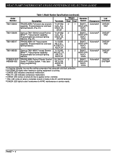
..., G,Y,R,O,B, E,X,X2,L Stages Systems Heat Cool Switch Changeover 2 1 EM.HT.- Manual heat HEAT-OFF- or cool AUX. COOL 2 1 OFF- HEAT- For use where E and W2 may be jumpered. HT. (Fig. 18). Includes T874G1204/Q674J1043. W1,W2,W3, Y1,G,R,O,B, E,X,X1,X2 Same as T841A1712, except Premier White™. HT. (Fig. 25). Manual heat EM.HT., HEAT-OFF- or cool AUX. HT. COOL 2 1 HEAT-OFF- Auto heat EM...
..., G,Y,R,O,B, E,X,X2,L Stages Systems Heat Cool Switch Changeover 2 1 EM.HT.- Manual heat HEAT-OFF- or cool AUX. COOL 2 1 OFF- HEAT- For use where E and W2 may be jumpered. HT. (Fig. 18). Includes T874G1204/Q674J1043. W1,W2,W3, Y1,G,R,O,B, E,X,X1,X2 Same as T841A1712, except Premier White™. HT. (Fig. 25). Manual heat EM.HT., HEAT-OFF- or cool AUX. HT. COOL 2 1 HEAT-OFF- Auto heat EM...
User Guide
Page 5
...,W1, 2 Thermostat. B,E,L 1 EM.-HT.HEAT-OFFCOOL Manual None TRADELINE®; Replaces Y594R1136. program up to four time R,C,G,W1, 2 periods and temperatures. Description Terminals Stages Systems Led Heat Cool Switch Changeover Indication TRADELINE®; Auto fan in EM.HT. (Fig. 27). Deluxe Electronic R,C,Y1,Y2, 3 Thermostat. TRADELINE®; 5-1-1 programming. AUX. E,L,OT,OT Same as T8411R1002 except Premier W1...
...,W1, 2 Thermostat. B,E,L 1 EM.-HT.HEAT-OFFCOOL Manual None TRADELINE®; Replaces Y594R1136. program up to four time R,C,G,W1, 2 periods and temperatures. Description Terminals Stages Systems Led Heat Cool Switch Changeover Indication TRADELINE®; Auto fan in EM.HT. (Fig. 27). Deluxe Electronic R,C,Y1,Y2, 3 Thermostat. TRADELINE®; 5-1-1 programming. AUX. E,L,OT,OT Same as T8411R1002 except Premier W1...
User Guide
Page 6
.... 31). full 7-day program Y1,Y2/W2, 3 capability. Automatica HEAT-OFF- COOL PC8900A1007/ TRADELINE®; c CHECK LED indicates compressor malfunction. Order Number Description Terminals Stages Systems Heat Cool Switch Changeover T8611G2002 TRADELINE®; O/B,X1,X2, OT,OT 1 EM.... is running. Automatica HEAT-OFF- COOL T8611M2025 Same as T8611G2002 except Premier Y1,W1,W2, 2 White™, 7-day program capability. HT. AUX,E,Y2, W2,L 2 EM.HT.- Model Number Specifications (continued). HEAT PUMP THERMOSTAT CROSS REFERENCE/SELECTION GUIDE...
.... 31). full 7-day program Y1,Y2/W2, 3 capability. Automatica HEAT-OFF- COOL PC8900A1007/ TRADELINE®; c CHECK LED indicates compressor malfunction. Order Number Description Terminals Stages Systems Heat Cool Switch Changeover T8611G2002 TRADELINE®; O/B,X1,X2, OT,OT 1 EM.... is running. Automatica HEAT-OFF- COOL T8611M2025 Same as T8611G2002 except Premier Y1,W1,W2, 2 White™, 7-day program capability. HT. AUX,E,Y2, W2,L 2 EM.HT.- Model Number Specifications (continued). HEAT PUMP THERMOSTAT CROSS REFERENCE/SELECTION GUIDE...
User Guide
Page 7
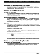
... reduces the call for specific heat pump applications. Electromechanical Heat Pump Thermostats T841 Heat Pump Thermostats The T841 models control two-stage heat and one -degree change in the heater. Select one -stage cool in memory (no batteries required) and retained during power failures. To correct this section also explains some of the heat pump thermostats that Honeywell manufactures. When this happens...
... reduces the call for specific heat pump applications. Electromechanical Heat Pump Thermostats T841 Heat Pump Thermostats The T841 models control two-stage heat and one -degree change in the heater. Select one -stage cool in memory (no batteries required) and retained during power failures. To correct this section also explains some of the heat pump thermostats that Honeywell manufactures. When this happens...
User Guide
Page 8
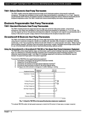
... low-speed and high-speed in either heating or cooling. HEAT PUMP THERMOSTAT CROSS REFERENCE/SELECTION GUIDE T8511 Deluxe Electronic Heat Pump Thermostats The T8511 models control two-stage heat and one -stage cool control for heat pump systems, using manual changeover. second stage heat anticipation is a three-stage heat/two-stage cool thermostat used to three-stage heat and two-stage cool control for heat pump systems, using manual or automatic changeover...
... low-speed and high-speed in either heating or cooling. HEAT PUMP THERMOSTAT CROSS REFERENCE/SELECTION GUIDE T8511 Deluxe Electronic Heat Pump Thermostats The T8511 models control two-stage heat and one -stage cool control for heat pump systems, using manual changeover. second stage heat anticipation is a three-stage heat/two-stage cool thermostat used to three-stage heat and two-stage cool control for heat pump systems, using manual or automatic changeover...
User Guide
Page 9
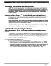
... Recovery™ control assures that provide changeover in the heating mode and for cooling, the Y terminal activates the first stage of the Chronotherm III T8611G and T8611M Y terminal. Honeywell does not recommend this requirement, a separate switching relay must... fan operation are ideal for stage 1 heat and stage 1 cool. HEAT PUMP THERMOSTAT CROSS REFERENCE/SELECTION GUIDE Chronotherm IV Electronic Deluxe Heat Pump Thermostats The T8611 Chronotherm IV thermostat models provide up mode in the Chronotherm IV thermostat. First stage heat anticipation is selectable. However,...
... Recovery™ control assures that provide changeover in the heating mode and for cooling, the Y terminal activates the first stage of the Chronotherm III T8611G and T8611M Y terminal. Honeywell does not recommend this requirement, a separate switching relay must... fan operation are ideal for stage 1 heat and stage 1 cool. HEAT PUMP THERMOSTAT CROSS REFERENCE/SELECTION GUIDE Chronotherm IV Electronic Deluxe Heat Pump Thermostats The T8611 Chronotherm IV thermostat models provide up mode in the Chronotherm IV thermostat. First stage heat anticipation is selectable. However,...
User Guide
Page 10
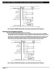
...® III T8611G and T8611M Y terminal. Now when the thermostat calls for cooling, the thermostat Y terminal activates the first stage of the R8222B Switching Relay. Equipment Function Power 1st Stage Cool 2nd Stage Cool Fan 1st Stage Heat 2nd Stage Heat Transformer Common Equipment Terminals R Y1 Y2 G W1 W2 C T8611M Terminals R Y2 G W2 C Y Cooling Changeover O B R8222B Relay O M13230 Fig. 3. Installing an R8222B Switching...
...® III T8611G and T8611M Y terminal. Now when the thermostat calls for cooling, the thermostat Y terminal activates the first stage of the R8222B Switching Relay. Equipment Function Power 1st Stage Cool 2nd Stage Cool Fan 1st Stage Heat 2nd Stage Heat Transformer Common Equipment Terminals R Y1 Y2 G W1 W2 C T8611M Terminals R Y2 G W2 C Y Cooling Changeover O B R8222B Relay O M13230 Fig. 3. Installing an R8222B Switching...
User Guide
Page 11
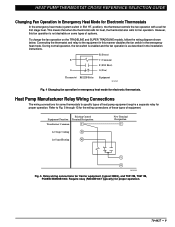
... TRADELINE models, follow the wiring diagram shown below. Existing Control Equipment Function Terminal Designation Transformer Common C 1st Stage Cooling Y1 1st Stage Heating W1 New Terminal Designation C Y O M13235 Fig. 5. R (Power) E C (Common) E (EM. HEAT PUMP THERMOSTAT CROSS REFERENCE/SELECTION GUIDE Changing Fan Operation in Emergency Heat Mode for fan operation. Relay wiring connections for some types of equipment.
... TRADELINE models, follow the wiring diagram shown below. Existing Control Equipment Function Terminal Designation Transformer Common C 1st Stage Cooling Y1 1st Stage Heating W1 New Terminal Designation C Y O M13235 Fig. 5. R (Power) E C (Common) E (EM. HEAT PUMP THERMOSTAT CROSS REFERENCE/SELECTION GUIDE Changing Fan Operation in Emergency Heat Mode for fan operation. Relay wiring connections for some types of equipment.
User Guide
Page 14
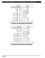
HEAT PUMP THERMOSTAT CROSS REFERENCE/SELECTION GUIDE Equipment Equipment Function Terminals Transformer Common C Power R Fan G 1st Stage Heating W1 1st Stage Cooling Y1 Changeover Valve B PC8900 Terminals C R G O/B Y1/W1 2nd Stage Heating W2 Aux. Relay wiring connections for PC8900 in heat pump applications requiring separate Y1 and W1 terminals with a cooling changeover. 70-6627 • 12 Emergency Heat E E 2nd Stage Cooling Y2 Y2 M13234...
HEAT PUMP THERMOSTAT CROSS REFERENCE/SELECTION GUIDE Equipment Equipment Function Terminals Transformer Common C Power R Fan G 1st Stage Heating W1 1st Stage Cooling Y1 Changeover Valve B PC8900 Terminals C R G O/B Y1/W1 2nd Stage Heating W2 Aux. Relay wiring connections for PC8900 in heat pump applications requiring separate Y1 and W1 terminals with a cooling changeover. 70-6627 • 12 Emergency Heat E E 2nd Stage Cooling Y2 Y2 M13234...

User Guide
Page 15
.... The system monitor relay may be wired to the L terminal on a temperature rise (auto changeover). C1-Stage 1 Cooling. C2-Stage 2 Cooling. Each schematic indicates switch operation by function: H1-Stage 1 Heating. HEAT PUMP THERMOSTAT CROSS REFERENCE/SELECTION GUIDE Understanding Circuits To understand wiring diagrams, it is important to know what all the symbols mean and how to trace...
.... The system monitor relay may be wired to the L terminal on a temperature rise (auto changeover). C1-Stage 1 Cooling. C2-Stage 2 Cooling. Each schematic indicates switch operation by function: H1-Stage 1 Heating. HEAT PUMP THERMOSTAT CROSS REFERENCE/SELECTION GUIDE Understanding Circuits To understand wiring diagrams, it is important to know what all the symbols mean and how to trace...

User Guide
Page 17
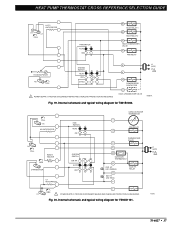
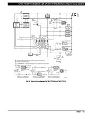
LED (GREEN) E L EM. RELAY SYSTEM MONITOR X LACO Y HEAT CHANGEOVER VALVE COMPRESSOR CONTACTOR O COOL CHANGEOVER VALVE CHP M6060A Fig. 16. HEAT PUMP THERMOSTAT CROSS REFERENCE/SELECTION GUIDE Typical System Hookup Diagrams L1 L2 (HOT) RTD 1 1 ODT 1 H1 C1 FALL H1/C1 ANTICIPATOR FAN SWITCH AUTO ON G R EHR 1 RTD 2 ...
LED (GREEN) E L EM. RELAY SYSTEM MONITOR X LACO Y HEAT CHANGEOVER VALVE COMPRESSOR CONTACTOR O COOL CHANGEOVER VALVE CHP M6060A Fig. 16. HEAT PUMP THERMOSTAT CROSS REFERENCE/SELECTION GUIDE Typical System Hookup Diagrams L1 L2 (HOT) RTD 1 1 ODT 1 H1 C1 FALL H1/C1 ANTICIPATOR FAN SWITCH AUTO ON G R EHR 1 RTD 2 ...
User Guide
Page 18
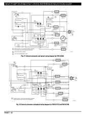
... for T841A1555. L2 1 L1 (HOT) M13249 70-6627 • 16 HT. HEAT OFF 1 RESET 4 COOL 1 POWER SUPPLY. HEAT LED (GRN) W2 FAN RELAY EM. HEAT RELAY B HEAT CHANGEOVER RELAY COMPRESSOR CONTACTOR Y Fig. 18. HEAT LED (GREEN) B EM. HEAT RELAY AUX. COMPRESSOR MONITOR R OUTDOOR THERMOSTAT X2 T OUTDOOR O THERMISTOR COOL CHANGEOVER RELAY COMPRESSOR CONTACTOR Y 2 FIELD REMOVABLE JUMPER. 3 AUTO FAN IN EMERGENCY...
... for T841A1555. L2 1 L1 (HOT) M13249 70-6627 • 16 HT. HEAT OFF 1 RESET 4 COOL 1 POWER SUPPLY. HEAT LED (GRN) W2 FAN RELAY EM. HEAT RELAY B HEAT CHANGEOVER RELAY COMPRESSOR CONTACTOR Y Fig. 18. HEAT LED (GREEN) B EM. HEAT RELAY AUX. COMPRESSOR MONITOR R OUTDOOR THERMOSTAT X2 T OUTDOOR O THERMISTOR COOL CHANGEOVER RELAY COMPRESSOR CONTACTOR Y 2 FIELD REMOVABLE JUMPER. 3 AUTO FAN IN EMERGENCY...
User Guide
Page 19
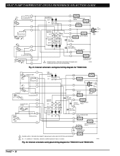
LED (GREEN) B EM. LED (RED) F AUX. Fig. 20. HEAT PUMP THERMOSTAT CROSS REFERENCE/SELECTION GUIDE H1/C1 ANTICIPATOR H1 C1 FALL FAN SWITCH AUTO ON W1 HEAT RELAY 1 W2 HEAT RELAY 2 B HEAT CHANGEOVER VALVE G FAN RELAY H2 ANTICIPATOR H2 FALL SYSTEM SWITCH HEAT OFF COOL 1 POWER SUPPLY. FALL H1 H1 ANTICIPATOR H2 FALL RESET HEATER RISE CHANGEOVER C1...
LED (GREEN) B EM. LED (RED) F AUX. Fig. 20. HEAT PUMP THERMOSTAT CROSS REFERENCE/SELECTION GUIDE H1/C1 ANTICIPATOR H1 C1 FALL FAN SWITCH AUTO ON W1 HEAT RELAY 1 W2 HEAT RELAY 2 B HEAT CHANGEOVER VALVE G FAN RELAY H2 ANTICIPATOR H2 FALL SYSTEM SWITCH HEAT OFF COOL 1 POWER SUPPLY. FALL H1 H1 ANTICIPATOR H2 FALL RESET HEATER RISE CHANGEOVER C1...
User Guide
Page 20
... MEANS AND OVERLOAD PROTECTION AS REQUIRED. 2 W1 - COMPRESSOR CONTACTOR M8702 Fig. 21. HT. LED (RED) X COOL CHANGEOVER VALVE O B W1 RELAY W1 HEAT CHANGEOVER VALVE 2 COMPRESSOR CONTACTOR Y1 1 POWER SUPPLY. REMOVE JUMPER WHEN W1 RELAY IS USED. HT. HT. H1 RISE...) H2 5 H2 ANTICIPATOR FALL 6 CHANGEOVER 8 (COOL) 9 RISE 10 C1 ANTICIPATOR C1 11 SYSTEM SWITCH OFF EM. HEAT AUTO COOL W2 E AUX. LED (RED) X AUX. HT. HEAT AUTO COOL O COOL CHANGEOVER VALVE G B RELAY FAN RELAY B R E EM. HEAT PUMP THERMOSTAT CROSS REFERENCE/SELECTION GUIDE FALL 1 H1 ANTICIPATOR 2 ...
... MEANS AND OVERLOAD PROTECTION AS REQUIRED. 2 W1 - COMPRESSOR CONTACTOR M8702 Fig. 21. HT. LED (RED) X COOL CHANGEOVER VALVE O B W1 RELAY W1 HEAT CHANGEOVER VALVE 2 COMPRESSOR CONTACTOR Y1 1 POWER SUPPLY. REMOVE JUMPER WHEN W1 RELAY IS USED. HT. HT. H1 RISE...) H2 5 H2 ANTICIPATOR FALL 6 CHANGEOVER 8 (COOL) 9 RISE 10 C1 ANTICIPATOR C1 11 SYSTEM SWITCH OFF EM. HEAT AUTO COOL W2 E AUX. LED (RED) X AUX. HT. HEAT AUTO COOL O COOL CHANGEOVER VALVE G B RELAY FAN RELAY B R E EM. HEAT PUMP THERMOSTAT CROSS REFERENCE/SELECTION GUIDE FALL 1 H1 ANTICIPATOR 2 ...
User Guide
Page 21
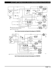
...) AUX. PROVIDE DISCONNECT MEANS AND OVERLOAD PROTECTION AS REQUIRED. HEAT PUMP THERMOSTAT CROSS REFERENCE/SELECTION GUIDE 1 2 H1 C1 FALL 3 4 H2 FALL 5 6 11 AUTO ON FAN SWITCH SYSTEM SWITCH EM. HEAT LED (RED) G FAN RELAY W 2 U AUX. HEAT OFF R L EM. HEAT RELAY W2 FAN RELAY G COOL CHANGEOVER VALVE O COOL E COMPRESSOR EM. PROVIDE DISCONNECT MEANS AND OVERLOAD PROTECTION AS REQUIRED...
...) AUX. PROVIDE DISCONNECT MEANS AND OVERLOAD PROTECTION AS REQUIRED. HEAT PUMP THERMOSTAT CROSS REFERENCE/SELECTION GUIDE 1 2 H1 C1 FALL 3 4 H2 FALL 5 6 11 AUTO ON FAN SWITCH SYSTEM SWITCH EM. HEAT LED (RED) G FAN RELAY W 2 U AUX. HEAT OFF R L EM. HEAT RELAY W2 FAN RELAY G COOL CHANGEOVER VALVE O COOL E COMPRESSOR EM. PROVIDE DISCONNECT MEANS AND OVERLOAD PROTECTION AS REQUIRED...
User Guide
Page 22
O COOL CHANGEOVER VALVE L COMPRESSOR MONITOR FAN RELAY G R EM. LED (RED) AUX. HT. PROVIDE DISCONNECT MEANS AND OVERLOAD PROTECTION AS REQUIRED. 2 REMOVE JUMPER WHEN W1 RELAY IS USED. 3 FACTORY-INSTALLED JUMPER. HT. HEAT PUMP THERMOSTAT CROSS REFERENCE/SELECTION GUIDE W3 W3 RELAY H1 ANTICIPATOR 1 C ANTICIPATOR 2 FAN SWITCH AUTO ON H1 3 C FALL 4 5 H2 ANTICIPATOR H2 6 FALL...
O COOL CHANGEOVER VALVE L COMPRESSOR MONITOR FAN RELAY G R EM. LED (RED) AUX. HT. PROVIDE DISCONNECT MEANS AND OVERLOAD PROTECTION AS REQUIRED. 2 REMOVE JUMPER WHEN W1 RELAY IS USED. 3 FACTORY-INSTALLED JUMPER. HT. HEAT PUMP THERMOSTAT CROSS REFERENCE/SELECTION GUIDE W3 W3 RELAY H1 ANTICIPATOR 1 C ANTICIPATOR 2 FAN SWITCH AUTO ON H1 3 C FALL 4 5 H2 ANTICIPATOR H2 6 FALL...
User Guide
Page 23
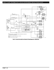
... (HOT) L2 SWITCH TO R (POWER) SIDE OF SYSTEM TRANSFORMER SWITCH TO C (COMMON) SIDE OF SYSTEM TRANSFORMER SWITCH IN SECONDARY OF SEPARATE TRANSFORMER M6020A Fig. 26. COOL CHANGEOVER VALVE O COOL C. PROVIDE DISCONNECT MEANS AND OVERLOAD PROTECTION AS REQUIRED. 2 DENOTES THERMOSTAT TO SUBBASE INTERCONNECT. HT. HT. HT. HEAT OFF AUTO COOL C. O.
... (HOT) L2 SWITCH TO R (POWER) SIDE OF SYSTEM TRANSFORMER SWITCH TO C (COMMON) SIDE OF SYSTEM TRANSFORMER SWITCH IN SECONDARY OF SEPARATE TRANSFORMER M6020A Fig. 26. COOL CHANGEOVER VALVE O COOL C. PROVIDE DISCONNECT MEANS AND OVERLOAD PROTECTION AS REQUIRED. 2 DENOTES THERMOSTAT TO SUBBASE INTERCONNECT. HT. HT. HT. HEAT OFF AUTO COOL C. O.
User Guide
Page 30
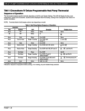
... Programmable Heat Pump Thermostat Sequence of Operation The thermostat energizes specific terminals depending on last piece of Operation. NOTE: Terminals listed in Installer Setup. The LCD will be displayed when the heating, cooling or fan is energized. Call None None None G Energize Display Icons None Auto Auto Auto Auto Cool Cool or Auto Heat Heat or Auto None Stage 1 Cooling None Stage 1 heating...
... Programmable Heat Pump Thermostat Sequence of Operation The thermostat energizes specific terminals depending on last piece of Operation. NOTE: Terminals listed in Installer Setup. The LCD will be displayed when the heating, cooling or fan is energized. Call None None None G Energize Display Icons None Auto Auto Auto Auto Cool Cool or Auto Heat Heat or Auto None Stage 1 Cooling None Stage 1 heating...
User Guide
Page 35
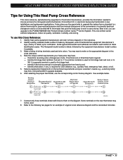
...-6627 • 33 Best of wiring terminals used . 8. The Honeywell model number is used for first stage heat. - Identify if device has manual or automatic changeover from a standard to a deluxe thermostat for an example of automatic heat/cool changeover and to a Chronotherm® IV thermostat that puts the heat pump to work to W1 if a separate terminal is...
...-6627 • 33 Best of wiring terminals used . 8. The Honeywell model number is used for first stage heat. - Identify if device has manual or automatic changeover from a standard to a deluxe thermostat for an example of automatic heat/cool changeover and to a Chronotherm® IV thermostat that puts the heat pump to work to W1 if a separate terminal is...


