
Owner's Manual
Page 1
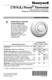
...purchased the correct CT87Thermostat for your heating/cooling system. No No * CT87A is right for your system, visit www.honeywell.com/ yourhome or call Honeywell Customer Care at 1-800-468-1502. CT87A,B,J Round® Thermostat LOW VOLTAGE (15 TO 30 VAC), THERMOSTAT ...AND MOUNTING HARDWARE 1 Verify that you have the correct thermostat Using the compatibility chart below, verify that you are unsure which model is compatible with 2-wire...
...purchased the correct CT87Thermostat for your heating/cooling system. No No * CT87A is right for your system, visit www.honeywell.com/ yourhome or call Honeywell Customer Care at 1-800-468-1502. CT87A,B,J Round® Thermostat LOW VOLTAGE (15 TO 30 VAC), THERMOSTAT ...AND MOUNTING HARDWARE 1 Verify that you have the correct thermostat Using the compatibility chart below, verify that you are unsure which model is compatible with 2-wire...
Owner's Manual
Page 2
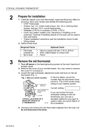
...-0274-6 2 drill bit • Wire cutter/stripper or sharp knife • Pencil 3 Remove the old thermostat 1. Mercury switch location. sheet metal screws, two 1/2-in . round head screws • Wallplate (CT87A) or subbase (CT87B, CT87J) • Cover ring (select models only). OLD THERMOSTAT ANTICIPATOR SCALE Current setting: If you cannot find the heat...
...-0274-6 2 drill bit • Wire cutter/stripper or sharp knife • Pencil 3 Remove the old thermostat 1. Mercury switch location. sheet metal screws, two 1/2-in . round head screws • Wallplate (CT87A) or subbase (CT87B, CT87J) • Cover ring (select models only). OLD THERMOSTAT ANTICIPATOR SCALE Current setting: If you cannot find the heat...
Owner's Manual
Page 3
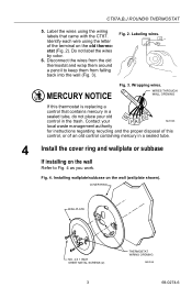
..., or of the terminal on the old thermo- M19086 MERCURY NOTICE Fig. 3. Wrapping wires. Fig. 2. Labeling wires. WIRES THROUGH WALL OPENING If this thermostat is replacing a control that came with the CT87. Label the wires using the letter of an old control containing mercury in the trash. Disconnect the...wall Refer to keep them from falling back into the wall (Fig. 3). COVER RING WALLPLATE NO. 4 X 1 INCH SHEET METAL SCREWS (2) 3 THERMOSTAT WIRING OPENING M20188 69-0274-6 Do not label the wires by color. 6. Fig. 4. CT87A,B,J ROUND® THERMOSTAT 5.
..., or of the terminal on the old thermo- M19086 MERCURY NOTICE Fig. 3. Wrapping wires. Fig. 2. Labeling wires. WIRES THROUGH WALL OPENING If this thermostat is replacing a control that came with the CT87. Label the wires using the letter of an old control containing mercury in the trash. Disconnect the...wall Refer to keep them from falling back into the wall (Fig. 3). COVER RING WALLPLATE NO. 4 X 1 INCH SHEET METAL SCREWS (2) 3 THERMOSTAT WIRING OPENING M20188 69-0274-6 Do not label the wires by color. 6. Fig. 4. CT87A,B,J ROUND® THERMOSTAT 5.
Owner's Manual
Page 4
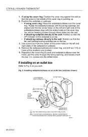
...Fig. 5 as you marked. 5. M20187 69-0274-6 4 If using cover ring: Place the wallplate/subbase over the holes, pull the wires through these holes into the drilled holes. Installing wallplate/subbase on the left and right side of the wallplate or subbase. 4. Position the wallplate... the wallplate is pointing up. 2. Reposition the cover ring (if used) and wallplate/subbase over the cover ring. CT87A,B,J ROUND® THERMOSTAT 1. ROUND HEAD SCREW (2) A THERMOSTAT WIRING HOLE 1 THE TWO INNER HOLES ARE USED WITH WALLPLATE. 2 IF OUTLET BOX IS HORIZONTAL, MOUNT COVER RING IN ...
...Fig. 5 as you marked. 5. M20187 69-0274-6 4 If using cover ring: Place the wallplate/subbase over the holes, pull the wires through these holes into the drilled holes. Installing wallplate/subbase on the left and right side of the wallplate or subbase. 4. Position the wallplate... the wallplate is pointing up. 2. Reposition the cover ring (if used) and wallplate/subbase over the cover ring. CT87A,B,J ROUND® THERMOSTAT 1. ROUND HEAD SCREW (2) A THERMOSTAT WIRING HOLE 1 THE TWO INNER HOLES ARE USED WITH WALLPLATE. 2 IF OUTLET BOX IS HORIZONTAL, MOUNT COVER RING IN ...
Owner's Manual
Page 5
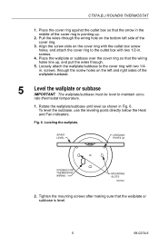
... the wallplate or subbase IMPORTANT: The wallplate/subbase must be level to the outlet box with two 1/4in. rate thermostat temperature. 1. CT87A,B,J ROUND® THERMOSTAT 1. Pull the wires through . 5. Align the screw slots on the bottom left and right sides of the cover ring is level. 5 69-0274-6 ...Place the cover ring against the outlet box so that the wallplate or subbase is pointing up , and pull the wires through the wiring hole on the cover ring with the outlet box screw holes, and attach the cover ring to maintain accu- Leveling the wallplate.
... the wallplate or subbase IMPORTANT: The wallplate/subbase must be level to the outlet box with two 1/4in. rate thermostat temperature. 1. CT87A,B,J ROUND® THERMOSTAT 1. Pull the wires through . 5. Align the screw slots on the bottom left and right sides of the cover ring is level. 5 69-0274-6 ...Place the cover ring against the outlet box so that the wallplate or subbase is pointing up , and pull the wires through the wiring hole on the cover ring with the outlet box screw holes, and attach the cover ring to maintain accu- Leveling the wallplate.
Owner's Manual
Page 6
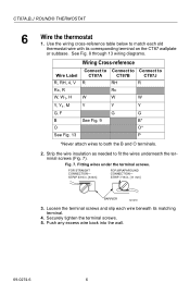
...] BARRIER M1279 3. FOR STRAIGHT CONNECTION- See Fig. 8 through 13 wiring diagrams. Wiring Cross-reference Wire Label R, RH, 4, V Rc, R W, W1, H Y, Y1, M G, F B O See Fig. 13 Connect to CT87A R W Y See Fig. 9 Connect to Connect to CT87B CT87J RH R Rc W W Y Y G G B* O* P *Never attach wires to fit the wires underneath the terminal screws (Fig. 7). Fitting wires under the terminal screws. Push any excess...
...] BARRIER M1279 3. FOR STRAIGHT CONNECTION- See Fig. 8 through 13 wiring diagrams. Wiring Cross-reference Wire Label R, RH, 4, V Rc, R W, W1, H Y, Y1, M G, F B O See Fig. 13 Connect to CT87A R W Y See Fig. 9 Connect to Connect to CT87B CT87J RH R Rc W W Y Y G G B* O* P *Never attach wires to fit the wires underneath the terminal screws (Fig. 7). Fitting wires under the terminal screws. Push any excess...
Owner's Manual
Page 7
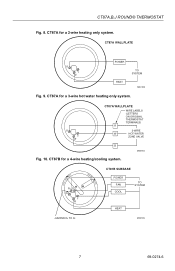
CT87A for a 4-wire heating/cooling system. CT87A,B,J ROUND® THERMOSTAT Fig. 8. COOL • OFF • HEAT FAN ON RH G RC Y W AUTO • CT87B SUBBASE POWER FAN COOL TO SYSTEM HEAT JUMPER RH TO RC M20185 7 69-0274-6 CT87B for a 3-wire hot water heating only system. R Y W CT87A WALLPLATE WIRE LABELS (LETTERS ON ORIGINAL THERMOSTAT TERMINALS) R 3-WIRE W HOT WATER ZONE VALVE B M20184 Fig. 10. CT87A WALLPLATE R Y W POWER HEAT TO SYSTEM M20183 Fig. 9. CT87A for a 2-wire heating only system.
CT87A for a 4-wire heating/cooling system. CT87A,B,J ROUND® THERMOSTAT Fig. 8. COOL • OFF • HEAT FAN ON RH G RC Y W AUTO • CT87B SUBBASE POWER FAN COOL TO SYSTEM HEAT JUMPER RH TO RC M20185 7 69-0274-6 CT87B for a 3-wire hot water heating only system. R Y W CT87A WALLPLATE WIRE LABELS (LETTERS ON ORIGINAL THERMOSTAT TERMINALS) R 3-WIRE W HOT WATER ZONE VALVE B M20184 Fig. 10. CT87A WALLPLATE R Y W POWER HEAT TO SYSTEM M20183 Fig. 9. CT87A for a 2-wire heating only system.
Owner's Manual
Page 8
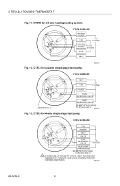
...O HEAT REVERSING VALVE COOL REVERSING VALVE TO SYSTEM HEAT PUMP COMPRESSOR DO NOT ATTACH WIRES TO BOTH B AND O 1 IF WIRES ARE ATTACHED TO Y OR W, AND P ON YOUR OLD THERMOSTAT, CONTACT YOUR ...LOCAL CONTRACTOR FOR FURTHER ASSISTANCE. M20228 69-0274-6 8 CT87B for a 4-wire single stage heat pump. M20225 COOL • OFF • HEAT FAN ON WG Y ...HEAT FAN TO SYSTEM POWER COOL REVERSING VALVE HEAT REVERSING VALVE DO NOT ATTACH WIRES TO BOTH B AND O M20186 Fig. 13. CT87J for 4-wire single stage heat pump. COOL • OFF • HEAT FAN ON ...
...O HEAT REVERSING VALVE COOL REVERSING VALVE TO SYSTEM HEAT PUMP COMPRESSOR DO NOT ATTACH WIRES TO BOTH B AND O 1 IF WIRES ARE ATTACHED TO Y OR W, AND P ON YOUR OLD THERMOSTAT, CONTACT YOUR ...LOCAL CONTRACTOR FOR FURTHER ASSISTANCE. M20228 69-0274-6 8 CT87B for a 4-wire single stage heat pump. M20225 COOL • OFF • HEAT FAN ON WG Y ...HEAT FAN TO SYSTEM POWER COOL REVERSING VALVE HEAT REVERSING VALVE DO NOT ATTACH WIRES TO BOTH B AND O M20186 Fig. 13. CT87J for 4-wire single stage heat pump. COOL • OFF • HEAT FAN ON ...


