
Owner's Manual
Page 1
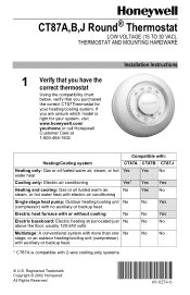
... water heat Yes No Cooling only: Electric air conditioning Yes* Yes Yes Heating and cooling: Gas or oil fueled warm air, No steam, or hot water heat with electric air conditioning Yes No Single stage heat pump: Outdoor heating/cooling unit No (compressor) with 2-wire cooling-only systems. ® U.S. No No * CT87A is right for your system, visit www.honeywell.com/ yourhome or call Honeywell Customer Care at 1-800-468-1502. CT87A,B,J Round® Thermostat LOW VOLTAGE (15...
... water heat Yes No Cooling only: Electric air conditioning Yes* Yes Yes Heating and cooling: Gas or oil fueled warm air, No steam, or hot water heat with electric air conditioning Yes No Single stage heat pump: Outdoor heating/cooling unit No (compressor) with 2-wire cooling-only systems. ® U.S. No No * CT87A is right for your system, visit www.honeywell.com/ yourhome or call Honeywell Customer Care at 1-800-468-1502. CT87A,B,J Round® Thermostat LOW VOLTAGE (15...
Owner's Manual
Page 2
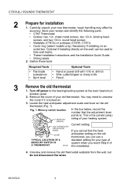
... the heat anticipator adjustment scale and lever on the wall; This is locked on an outlet box. sheet metal screws, two 1/2-in . Turn off power to . Carefully unpack your old thermostat. can use a TYPICAL LOCATION OF A standard setting for installation 1. Optional if installing directly on the old thermostat (Fig. 1). CT87A,B,J ROUND® THERMOSTAT 2 Prepare for your type of MERCURY SWITCH IN A THERMOSTAT system when you can be used to unscrew the cover if...
... the heat anticipator adjustment scale and lever on the wall; This is locked on an outlet box. sheet metal screws, two 1/2-in . Turn off power to . Carefully unpack your old thermostat. can use a TYPICAL LOCATION OF A standard setting for installation 1. Optional if installing directly on the old thermostat (Fig. 1). CT87A,B,J ROUND® THERMOSTAT 2 Prepare for your type of MERCURY SWITCH IN A THERMOSTAT system when you can be used to unscrew the cover if...
Owner's Manual
Page 3
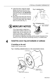
... work. Label the wires using the letter of an old control containing mercury in the trash. WIRES THROUGH WALL OPENING If this control, or of the terminal on the old thermo- COVER RING WALLPLATE NO. 4 X 1 INCH SHEET METAL SCREWS (2) 3 THERMOSTAT WIRING OPENING M20188 69-0274-6 Fig. 4. CT87A,B,J ROUND® THERMOSTAT 5. Labeling wires. Wrapping wires. Contact your old control in a sealed tube. 4 Install the cover ring and wallplate or subbase If installing on the wall...
... work. Label the wires using the letter of an old control containing mercury in the trash. WIRES THROUGH WALL OPENING If this control, or of the terminal on the old thermo- COVER RING WALLPLATE NO. 4 X 1 INCH SHEET METAL SCREWS (2) 3 THERMOSTAT WIRING OPENING M20188 69-0274-6 Fig. 4. CT87A,B,J ROUND® THERMOSTAT 5. Labeling wires. Wrapping wires. Contact your old control in a sealed tube. 4 Install the cover ring and wallplate or subbase If installing on the wall...
Owner's Manual
Page 4
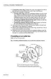
... shown). 1/2 IN. If installing on the cover ring. You will be inserting screws through the wiring opening, and loosely insert the two 1-in. BINDING HEAD SCREW (2) OUTLET BOX 1 2 COVER RING SUBBASE 1/4 IN. Position the wallplate or subbase. • If using the cover ring: Position the cover ring against the wall so that the fan and heating/cooling switches are aligned and the...
... shown). 1/2 IN. If installing on the cover ring. You will be inserting screws through the wiring opening, and loosely insert the two 1-in. BINDING HEAD SCREW (2) OUTLET BOX 1 2 COVER RING SUBBASE 1/4 IN. Position the wallplate or subbase. • If using the cover ring: Position the cover ring against the wall so that the fan and heating/cooling switches are aligned and the...
Owner's Manual
Page 5
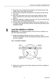
... wires through the screw holes on the left side of the wallplate/subbase. 5 Level the wallplate or subbase IMPORTANT: The wallplate/subbase must be level to maintain accu- To level the subbase, use the leveling posts directly below the Heat and Fan indicators. Align the screw slots on the bottom left and right sides of the cover...
... wires through the screw holes on the left side of the wallplate/subbase. 5 Level the wallplate or subbase IMPORTANT: The wallplate/subbase must be level to maintain accu- To level the subbase, use the leveling posts directly below the Heat and Fan indicators. Align the screw slots on the bottom left and right sides of the cover...
Owner's Manual
Page 6
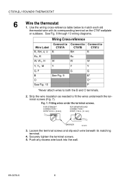
CT87A,B,J ROUND® THERMOSTAT 6 Wire the thermostat 1. Strip the wire insulation as needed to both the B and O terminals. 2. Fig. 7. Push any excess wire back into the wall. 69-0274-6 6 FOR STRAIGHT CONNECTION- Securely tighten the terminal screws. 5. STRIP 5/16 in . [11 mm] BARRIER M1279 3. Fitting wires under the terminal screws. Loosen the terminal screws and slip each old thermostat wire with its matching terminal. 4. Use the wiring cross-reference table below to...
CT87A,B,J ROUND® THERMOSTAT 6 Wire the thermostat 1. Strip the wire insulation as needed to both the B and O terminals. 2. Fig. 7. Push any excess wire back into the wall. 69-0274-6 6 FOR STRAIGHT CONNECTION- Securely tighten the terminal screws. 5. STRIP 5/16 in . [11 mm] BARRIER M1279 3. Fitting wires under the terminal screws. Loosen the terminal screws and slip each old thermostat wire with its matching terminal. 4. Use the wiring cross-reference table below to...
Owner's Manual
Page 7
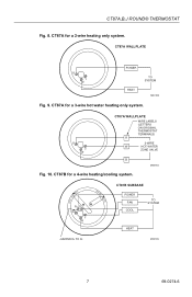
CT87A WALLPLATE R Y W POWER HEAT TO SYSTEM M20183 Fig. 9. R Y W CT87A WALLPLATE WIRE LABELS (LETTERS ON ORIGINAL THERMOSTAT TERMINALS) R 3-WIRE W HOT WATER ZONE VALVE B M20184 Fig. 10. CT87B for a 3-wire hot water heating only system. CT87A,B,J ROUND® THERMOSTAT Fig. 8. CT87A for a 4-wire heating/cooling system. COOL • OFF • HEAT FAN ON RH G RC Y W AUTO • CT87B SUBBASE POWER FAN COOL TO SYSTEM HEAT JUMPER RH TO RC M20185 7 69-0274-6 CT87A for a 2-wire heating only system.
CT87A WALLPLATE R Y W POWER HEAT TO SYSTEM M20183 Fig. 9. R Y W CT87A WALLPLATE WIRE LABELS (LETTERS ON ORIGINAL THERMOSTAT TERMINALS) R 3-WIRE W HOT WATER ZONE VALVE B M20184 Fig. 10. CT87B for a 3-wire hot water heating only system. CT87A,B,J ROUND® THERMOSTAT Fig. 8. CT87A for a 4-wire heating/cooling system. COOL • OFF • HEAT FAN ON RH G RC Y W AUTO • CT87B SUBBASE POWER FAN COOL TO SYSTEM HEAT JUMPER RH TO RC M20185 7 69-0274-6 CT87A for a 2-wire heating only system.
Owner's Manual
Page 8
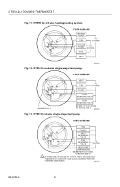
... COOLING POWER TO SYSTEM COOL HEAT Fig. 12. CT87J SUBBASE HEAT FAN ON FAN COOL • OFF • AUTO • POWER WG 1Y P R B O HEAT REVERSING VALVE COOL REVERSING VALVE TO SYSTEM HEAT PUMP COMPRESSOR DO NOT ATTACH WIRES TO BOTH B AND O 1 IF WIRES ARE ATTACHED TO Y OR W, AND P ON YOUR OLD THERMOSTAT, CONTACT YOUR LOCAL CONTRACTOR FOR FURTHER ASSISTANCE. CT87J for a 5-wire heating/cooling system. M20228 69-0274-6 8 CT87J for 4-wire single stage heat pump. CT87A,B,J ROUND® THERMOSTAT...
... COOLING POWER TO SYSTEM COOL HEAT Fig. 12. CT87J SUBBASE HEAT FAN ON FAN COOL • OFF • AUTO • POWER WG 1Y P R B O HEAT REVERSING VALVE COOL REVERSING VALVE TO SYSTEM HEAT PUMP COMPRESSOR DO NOT ATTACH WIRES TO BOTH B AND O 1 IF WIRES ARE ATTACHED TO Y OR W, AND P ON YOUR OLD THERMOSTAT, CONTACT YOUR LOCAL CONTRACTOR FOR FURTHER ASSISTANCE. CT87J for a 5-wire heating/cooling system. M20228 69-0274-6 8 CT87J for 4-wire single stage heat pump. CT87A,B,J ROUND® THERMOSTAT...
Owner's Manual
Page 9
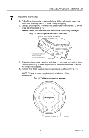
Using a pencil point, slide the heat anticipator indicator to 1.2 on the wallplate/subbase. 4. Adjusting heat anticipator indicator. Fig. 15. CT87A,B,J ROUND® THERMOSTAT 7 Mount the thermostat 1. Fig. 14. Tighten the three captive mounting screws as shown in Fig. 14. NOTE: These screws complete the installation of the thermostat. Tightening mounting screws. HEAT ANTICIPATOR INDICATOR 1.2 .6 .5 .4 .3 .2 HOLE SUITABLE FOR PENCIL POINT TO MOVE INDICATOR .15 SCALE .12 .10 M20226 3. IMPORTANT: This...
Using a pencil point, slide the heat anticipator indicator to 1.2 on the wallplate/subbase. 4. Adjusting heat anticipator indicator. Fig. 15. CT87A,B,J ROUND® THERMOSTAT 7 Mount the thermostat 1. Fig. 14. Tighten the three captive mounting screws as shown in Fig. 14. NOTE: These screws complete the installation of the thermostat. Tightening mounting screws. HEAT ANTICIPATOR INDICATOR 1.2 .6 .5 .4 .3 .2 HOLE SUITABLE FOR PENCIL POINT TO MOVE INDICATOR .15 SCALE .12 .10 M20226 3. IMPORTANT: This...
Owner's Manual
Page 10
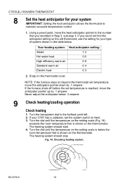
..., set temperature is shown on the thermostat cover. The heating system should stop. If you recorded in the table below. Turn the transparent dial to maintain accurate temperature control. 1. Checking heating system. Fig. 16. Your heating system: Steam Hot water heat High-efficiency warm air Standard warm air Electric heat Heat anticipator setting: 1.2 0.8 0.8 0.4 0.3 2. Snap on the thermometer. Using a pencil point, move the anticipator pointer up by .1 ampere. CT87A,B,J ROUND® THERMOSTAT 8 Set the heat anticipator for...
..., set temperature is shown on the thermostat cover. The heating system should stop. If you recorded in the table below. Turn the transparent dial to maintain accurate temperature control. 1. Checking heating system. Fig. 16. Your heating system: Steam Hot water heat High-efficiency warm air Standard warm air Electric heat Heat anticipator setting: 1.2 0.8 0.8 0.4 0.3 2. Snap on the thermometer. Using a pencil point, move the anticipator pointer up by .1 ampere. CT87A,B,J ROUND® THERMOSTAT 8 Set the heat anticipator for...
Owner's Manual
Page 11
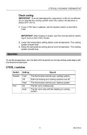
... temperature setting above room temperature. The fan runs continuously. The fan runs only with the desired temperature. CT87A,B,J ROUND® THERMOSTAT Check cooling IMPORTANT: To avoid damaging the compressor in the air conditioner, do not operate the cooling system when the outdoor temperature is tested, wait five minutes before switching to Cool. If your CT87 has a subbase, set the temperature, turn the dial until the pointer on the CT87J model. 2. IMPORTANT: After heating is below room temperature...
... temperature setting above room temperature. The fan runs continuously. The fan runs only with the desired temperature. CT87A,B,J ROUND® THERMOSTAT Check cooling IMPORTANT: To avoid damaging the compressor in the air conditioner, do not operate the cooling system when the outdoor temperature is tested, wait five minutes before switching to Cool. If your CT87 has a subbase, set the temperature, turn the dial until the pointer on the CT87J model. 2. IMPORTANT: After heating is below room temperature...
Owner's Manual
Page 12
..., Honeywell Limited/Honeywell Limitée, 35 Dynamic Drive, Scarborough, Ontario M1V 4Z9. If the product is defective, (i) return it , postage prepaid, to the following address: Honeywell Inc. on how long an implied warranty lasts, so the above . CT87A,B,J ROUND® THERMOSTAT Limited One-Year Warranty Honeywell warrants this product, excluding battery, to be to repair or replace the product within a reasonable period of time.
..., Honeywell Limited/Honeywell Limitée, 35 Dynamic Drive, Scarborough, Ontario M1V 4Z9. If the product is defective, (i) return it , postage prepaid, to the following address: Honeywell Inc. on how long an implied warranty lasts, so the above . CT87A,B,J ROUND® THERMOSTAT Limited One-Year Warranty Honeywell warrants this product, excluding battery, to be to repair or replace the product within a reasonable period of time.


