
Owner's Manual
Page 1
... 1. Prepare for Installation ...5 Step 2. Programming ...13 Step 10. Mount Thermostat Wallplate ...7 Step 4. Wire Wallplate Terminals ...8 Step 5. Customize Your Thermostat ...11 Step 8. Remove Old Thermostat ...6 Step 3. Weekday, Saturday and Sunday Programmable Heat and/or Cool Low Voltage (20 to 30 Vac) Thermostat and Wallplate Model CT3550 Honeywell CT3550 PROGRAMMABLE THERMOSTAT OWNER'S GUIDE Para pedir estas instrucciones en españ...
... 1. Prepare for Installation ...5 Step 2. Programming ...13 Step 10. Mount Thermostat Wallplate ...7 Step 4. Wire Wallplate Terminals ...8 Step 5. Customize Your Thermostat ...11 Step 8. Remove Old Thermostat ...6 Step 3. Weekday, Saturday and Sunday Programmable Heat and/or Cool Low Voltage (20 to 30 Vac) Thermostat and Wallplate Model CT3550 Honeywell CT3550 PROGRAMMABLE THERMOSTAT OWNER'S GUIDE Para pedir estas instrucciones en españ...
Owner's Manual
Page 2
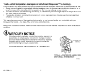
...the house at 1-800-468-1502. the state of this thermostat is replacing a control that contains mercury in a sealed tube, do not place your old control in comfort and convenience. Failure to have questions, call Honeywell Inc. If you comfortable by automatically calculating exactly when the ...the preprogrammed schedule, or set your own. MERCURY NOTICE If this control, or of energy and money by purchasing your new Honeywell thermostat the smart thermostat that can arise as you leave home or go on to follow these instructions carefully. at the desired comfort temperature by ...
...the house at 1-800-468-1502. the state of this thermostat is replacing a control that contains mercury in a sealed tube, do not place your old control in comfort and convenience. Failure to have questions, call Honeywell Inc. If you comfortable by automatically calculating exactly when the ...the preprogrammed schedule, or set your own. MERCURY NOTICE If this control, or of energy and money by purchasing your new Honeywell thermostat the smart thermostat that can arise as you leave home or go on to follow these instructions carefully. at the desired comfort temperature by ...
Owner's Manual
Page 3
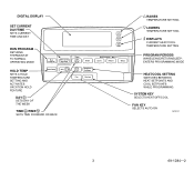
DIGITAL DISPLAY SET CURRENT DAY/TIME SETS CURRENT TIME AND DAY RUN PROGRAM RETURNS THERMOSTAT TO NORMAL OPERATING MODE Run Program Set Current Day/Time Time Wake Set Program Leave Return Sleep HOLD TEMP SETS A HOLD TEMPERATURE SETTING AND ACTIVATES ...
DIGITAL DISPLAY SET CURRENT DAY/TIME SETS CURRENT TIME AND DAY RUN PROGRAM RETURNS THERMOSTAT TO NORMAL OPERATING MODE Run Program Set Current Day/Time Time Wake Set Program Leave Return Sleep HOLD TEMP SETS A HOLD TEMPERATURE SETTING AND ACTIVATES ...

Owner's Manual
Page 4
... DISPLAYED IS THE CURRENT ROOM TEMPERATURE SHOWS THE BATTERIES ARE LOW AND MUST BE REPLACED SHOWS CURRENT SYSTEM KEY POSITION HEAT/OFF/COOL SHOWS THAT THERMOSTAT IS "CALLING" FOR HEAT OR COOL DISPLAYS EITHER ROOM OR SET TEMPERATURES SHOWS CURRENT FAN KEY POSITION ON/AUTO SHOWS... THERMOSTAT IS CALLING FOR THE FAN SHOWS THERMOSTAT IS PROCESSING INFORMATION AND WAITING TO CALL FOR HEAT OR COOL SHOWS SMART RESPONSE IS OFF. CONVENTIONAL RECOVERY IS ON SHOWS SMART RESPONSE IS CHANGING...
... DISPLAYED IS THE CURRENT ROOM TEMPERATURE SHOWS THE BATTERIES ARE LOW AND MUST BE REPLACED SHOWS CURRENT SYSTEM KEY POSITION HEAT/OFF/COOL SHOWS THAT THERMOSTAT IS "CALLING" FOR HEAT OR COOL DISPLAYS EITHER ROOM OR SET TEMPERATURES SHOWS CURRENT FAN KEY POSITION ON/AUTO SHOWS... THERMOSTAT IS CALLING FOR THE FAN SHOWS THERMOSTAT IS PROCESSING INFORMATION AND WAITING TO CALL FOR HEAT OR COOL SHOWS SMART RESPONSE IS OFF. CONVENTIONAL RECOVERY IS ON SHOWS SMART RESPONSE IS CHANGING...
Owner's Manual
Page 5
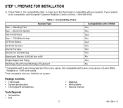
...Furnace Electric Air Conditioning Baseboard Electric (120/240 line volt)b Single Stage Heat Pump Multistage Heat Pumps/Multistage Equipment Compatibility with CT3550 Yes Yes Yesa Yes Yesa Yes Yes Yes No Yes No a Compatible with any 120/240 volt system. If your ...FOR INSTALLATION ❑ Check Table 1, the compatibility chart, to make sure the thermostat is not compatible, call Honeywell Customer Relations Center, toll-free, 1-800-468-1502. Table 1. Standing Pilot Gas - Gas - Package Contents. • Thermostat • Screws and anchors • 3 Energizer® AA batteries •...
...Furnace Electric Air Conditioning Baseboard Electric (120/240 line volt)b Single Stage Heat Pump Multistage Heat Pumps/Multistage Equipment Compatibility with CT3550 Yes Yes Yesa Yes Yesa Yes Yes Yes No Yes No a Compatible with any 120/240 volt system. If your ...FOR INSTALLATION ❑ Check Table 1, the compatibility chart, to make sure the thermostat is not compatible, call Honeywell Customer Relations Center, toll-free, 1-800-468-1502. Table 1. Standing Pilot Gas - Gas - Package Contents. • Thermostat • Screws and anchors • 3 Energizer® AA batteries •...
Owner's Manual
Page 6
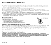
...the place of purchase. WIRES THROUGH WALL OPENING M5136 Replacing a Clock Thermostat that has Six or More Wires If there are replacing a Honeywell Chronotherm® Thermostat, you probably have a variation of the new thermostat. Place the wires where they do not operate the cooling system when... are only two wires, they will work , contact your system, call Honeywell Customer Relations Center, at the furnace or the fuse/circuit breaker panel. ❑ Carefully unpack your new thermostat and wallplate. Special Installations Read this section if you disconnect each wire, attach...
...the place of purchase. WIRES THROUGH WALL OPENING M5136 Replacing a Clock Thermostat that has Six or More Wires If there are replacing a Honeywell Chronotherm® Thermostat, you probably have a variation of the new thermostat. Place the wires where they do not operate the cooling system when... are only two wires, they will work , contact your system, call Honeywell Customer Relations Center, at the furnace or the fuse/circuit breaker panel. ❑ Carefully unpack your new thermostat and wallplate. Special Installations Read this section if you disconnect each wire, attach...
Owner's Manual
Page 7
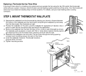
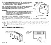
...provided) anchors into each of the wallplate and the thermostat, and pulling the wallplate up and away from the thermostat by placing your local heating and/or cooling contractor. MOUNT THERMOSTAT WALLPLATE ❑ Separate the wallplate from the thermostat. For materials such as shown. WALL WIRES THROUGH WALL... for appearance if desired. Level the wallplate for a heating only system and can operate the fan using the fan ON switch this thermostat works with the wall. ❑ Reposition the wallplate over the holes. holes in wall (if drywall) as plaster or wood, drill...
...provided) anchors into each of the wallplate and the thermostat, and pulling the wallplate up and away from the thermostat by placing your local heating and/or cooling contractor. MOUNT THERMOSTAT WALLPLATE ❑ Separate the wallplate from the thermostat. For materials such as shown. WALL WIRES THROUGH WALL... for appearance if desired. Level the wallplate for a heating only system and can operate the fan using the fan ON switch this thermostat works with the wall. ❑ Reposition the wallplate over the holes. holes in wall (if drywall) as plaster or wood, drill...
Owner's Manual
Page 8
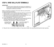
...terminal. Tighten the terminals. FOR STRAIGHT INSERTION STRIP 5/16 IN. (8 MM). If unsure about household wiring procedures, call your new thermostat. FOR WRAPAROUND INSERTION STRIP 7/16 IN. (11 MM). Wraparound and straight connections are connected to Table 2. ❑ Remove the factory... M4826 M16425 ❑ Plug the hole in the wall with local codes and ordinances. Refer to help prevent drafts from adversely affecting thermostat operation. 69-1284-2 8 STEP 4. WIRE WALLPLATE TERMINALS IMPORTANT All wiring must comply with insulation to the labels you placed on your...
...terminal. Tighten the terminals. FOR STRAIGHT INSERTION STRIP 5/16 IN. (8 MM). If unsure about household wiring procedures, call your new thermostat. FOR WRAPAROUND INSERTION STRIP 7/16 IN. (11 MM). Wraparound and straight connections are connected to Table 2. ❑ Remove the factory... M4826 M16425 ❑ Plug the hole in the wall with local codes and ordinances. Refer to help prevent drafts from adversely affecting thermostat operation. 69-1284-2 8 STEP 4. WIRE WALLPLATE TERMINALS IMPORTANT All wiring must comply with insulation to the labels you placed on your...
Owner's Manual
Page 9
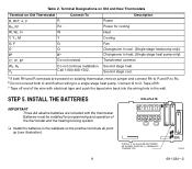
...1502. INSTALL THE BATTERIES IMPORTANT Three AA alkaline batteries are present on Old Thermostat Connect To Description R, RHa, 4, V R Power Rc, Ra Rc Power for programming and operation of the wire with the thermostat. Bb Bb Changeover in cool. (Single stage heat pump only). Second...Table 2. Second stage cool. c Tape off B. Terminal Designations on Old and New Thermostats Terminal on existing thermostat, remove jumper and connect Rh to R and R to Rc. Tape off end of the thermostat and the heating/cooling system. ❑ Install the batteries in the wall. STEP 5....
...1502. INSTALL THE BATTERIES IMPORTANT Three AA alkaline batteries are present on Old Thermostat Connect To Description R, RHa, 4, V R Power Rc, Ra Rc Power for programming and operation of the wire with the thermostat. Bb Bb Changeover in cool. (Single stage heat pump only). Second...Table 2. Second stage cool. c Tape off B. Terminal Designations on Old and New Thermostats Terminal on existing thermostat, remove jumper and connect Rh to R and R to Rc. Tape off end of the thermostat and the heating/cooling system. ❑ Install the batteries in the wall. STEP 5....
Owner's Manual
Page 10
... and to prevent the thermostat and heating/cooling system from shutting down due to lack of power. Nonalkaline 60 70 80 90 batteries do not last as shown. MOUNT THE THERMOSTAT A. When the batteries are dead or installed incorrectly. Honeywell recommends Energizer® batteries.... B. If you insert new batteries within 20 to the thermostat and the wall surface. ❑ If the thermostat is blank, the batteries are running low...
... and to prevent the thermostat and heating/cooling system from shutting down due to lack of power. Nonalkaline 60 70 80 90 batteries do not last as shown. MOUNT THE THERMOSTAT A. When the batteries are dead or installed incorrectly. Honeywell recommends Energizer® batteries.... B. If you insert new batteries within 20 to the thermostat and the wall surface. ❑ If the thermostat is blank, the batteries are running low...
Owner's Manual
Page 11
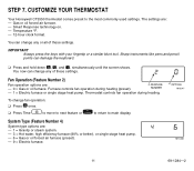
... or single stage heat pump. OPTION M13347 M13348 11 69-1284-2 Smart Response technology on. - Furnace controls fan operation during heating. Thermostat controls fan operation during heating (preset). CUSTOMIZE YOUR THERMOSTAT Your Honeywell CT3550 thermostat comes preset to main display. Temperature °F. - 12-hour clock format. To change any or all of these settings. System...
... or single stage heat pump. OPTION M13347 M13348 11 69-1284-2 Smart Response technology on. - Furnace controls fan operation during heating. Thermostat controls fan operation during heating (preset). CUSTOMIZE YOUR THERMOSTAT Your Honeywell CT3550 thermostat comes preset to main display. Temperature °F. - 12-hour clock format. To change any or all of these settings. System...
Owner's Manual
Page 13
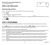
The thermostat displays day, time, program period, temperature, system and fan settings. STEP 8. PROGRAMMING The keyboard is a lower Sleep temperature during the heating season and a higher temperature ... when you want the house at a comfortable temperature when you get ready for an energy-saving temperature while you sleeping. (This is located behind the thermostat cover. Pressing the and keys change this setting. Leave (This is a lower temperature during the heating season and a higher temperature during the cooling season). -The...
The thermostat displays day, time, program period, temperature, system and fan settings. STEP 8. PROGRAMMING The keyboard is a lower Sleep temperature during the heating season and a higher temperature ... when you want the house at a comfortable temperature when you get ready for an energy-saving temperature while you sleeping. (This is located behind the thermostat cover. Pressing the and keys change this setting. Leave (This is a lower temperature during the heating season and a higher temperature during the cooling season). -The...
Owner's Manual
Page 14
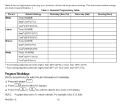
NOTE: Program times are shown in parentheses ( ). The thermostat default settings are in the display. Table 3. Wake ❑ Press Day until the (Mon-Fri) displays. ❑ Press Time or key until the desired time ...
NOTE: Program times are shown in parentheses ( ). The thermostat default settings are in the display. Table 3. Wake ❑ Press Day until the (Mon-Fri) displays. ❑ Press Time or key until the desired time ...
Owner's Manual
Page 16
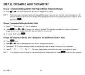
... Temp then or to change your setting if desired. (The display changes from showing the setpoint temperature to the program. 69-1284-2 16 OPERATING YOUR THERMOSTAT Change Temperature Setting Until the Next Program Period (Temporary Change) ❑ Press or until "Heat" or "Cool" is displayed.
... Temp then or to change your setting if desired. (The display changes from showing the setpoint temperature to the program. 69-1284-2 16 OPERATING YOUR THERMOSTAT Change Temperature Setting Until the Next Program Period (Temporary Change) ❑ Press or until "Heat" or "Cool" is displayed.
Owner's Manual
Page 17
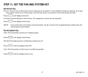
... the heating and air conditioning systems are off. Press Fan until the display shows Off. Press System until display shows On. Cool: The thermostat controls your heating system. STEP 11. Press System until display shows Auto. NOTE: If you set the fan to On during normal operation,... the fan reverts to the G thermostat terminal). Use for most homes. The equipment controls the fan operation. Set the System Key Heat: The thermostat controls your air conditioning system. Press Fan until display shows Heat. Press System until the...
... the heating and air conditioning systems are off. Press Fan until the display shows Off. Press System until display shows On. Cool: The thermostat controls your heating system. STEP 11. Press System until display shows Auto. NOTE: If you set the fan to On during normal operation,... the fan reverts to the G thermostat terminal). Use for most homes. The equipment controls the fan operation. Set the System Key Heat: The thermostat controls your air conditioning system. Press Fan until display shows Heat. Press System until the...
Owner's Manual
Page 18
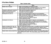
... minutes after seeing the flame or snowflake and check the registers again. The temperature setting limit has been reached. Solution Guide. Mount and latch the thermostat on indicator ( = heat, = cool) is lit, but no hot or cool air coming from the registers, refer to Heat. Heating does ... and set it to Cool. Temperature settings will not change • Make sure the temperature setpoints are installed correctly. • Make sure the thermostat is mounted and latched on . • Make sure the cooling setpoint is below the room temperature. • Make sure the circuit breaker is...
... minutes after seeing the flame or snowflake and check the registers again. The temperature setting limit has been reached. Solution Guide. Mount and latch the thermostat on indicator ( = heat, = cool) is lit, but no hot or cool air coming from the registers, refer to Heat. Heating does ... and set it to Cool. Temperature settings will not change • Make sure the temperature setpoints are installed correctly. • Make sure the thermostat is mounted and latched on . • Make sure the cooling setpoint is below the room temperature. • Make sure the circuit breaker is...
Owner's Manual
Page 19
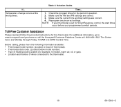
... below model number). • Type of heating/cooling system (for this thermostat. Solution Guide. Make sure the AM and PM settings are Monday through Friday, 7:00AM to www.honeywell.com/yourhome or call the Honeywell Customer Relations Center at the wrong times. Table 4. Check the program times... for Smart Response control, the start times occur before your thermostat is set for the period in question. 2. The...
... below model number). • Type of heating/cooling system (for this thermostat. Solution Guide. Make sure the AM and PM settings are Monday through Friday, 7:00AM to www.honeywell.com/yourhome or call the Honeywell Customer Relations Center at the wrong times. Table 4. Check the program times... for Smart Response control, the start times occur before your thermostat is set for the period in question. 2. The...
Owner's Manual
Page 20
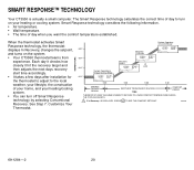
... considers the following information. • Air temperature. • Wall temperature. • The time of your home, and your heating or cooling system. Customize Your Thermostat. TEMPERATURE System Operating in Comfort Mode 68°F Recovery Continues AM Mon Wake System Heat Room 66°F 64°F System Operating in Energy Savings... it hit the recovery target and then adjusts the next days recovery start time accordingly. • It takes a few days after installation for the thermostat to adjust to turn on the system. • Your CT3550 thermostat learns from experience.
... considers the following information. • Air temperature. • Wall temperature. • The time of your home, and your heating or cooling system. Customize Your Thermostat. TEMPERATURE System Operating in Comfort Mode 68°F Recovery Continues AM Mon Wake System Heat Room 66°F 64°F System Operating in Energy Savings... it hit the recovery target and then adjusts the next days recovery start time accordingly. • It takes a few days after installation for the thermostat to adjust to turn on the system. • Your CT3550 thermostat learns from experience.
Owner's Manual
Page 21
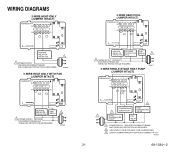
...M12739 21 69-1284-2 PROVIDE DISCONNECT MEANS AND OVERLOAD PROTECTION AS REQUIRED. 4-WIRE SINGLE-STAGE HEAT PUMP (JUMPER INTACT) M10617 THERMOSTAT B RC O W Y R G 3 2 COMPRESSOR HEAT CHANGEOVER CONTACTOR 2 VALVE 1 COOL CHANGEOVER FAN VALVE RELAY 1 POWER SUPPLY. M10616 3-...WIRE HEAT ONLY WITH FAN (JUMPER INTACT) THERMOSTAT B RC O W Y R G HEATING RELAY OR VALVE COIL FAN RELAY 1 POWER SUPPLY. PROVIDE DISCONNECT MEANS AND OVERLOAD PROTECTION AS REQUIRED...
...M12739 21 69-1284-2 PROVIDE DISCONNECT MEANS AND OVERLOAD PROTECTION AS REQUIRED. 4-WIRE SINGLE-STAGE HEAT PUMP (JUMPER INTACT) M10617 THERMOSTAT B RC O W Y R G 3 2 COMPRESSOR HEAT CHANGEOVER CONTACTOR 2 VALVE 1 COOL CHANGEOVER FAN VALVE RELAY 1 POWER SUPPLY. M10616 3-...WIRE HEAT ONLY WITH FAN (JUMPER INTACT) THERMOSTAT B RC O W Y R G HEATING RELAY OR VALVE COIL FAN RELAY 1 POWER SUPPLY. PROVIDE DISCONNECT MEANS AND OVERLOAD PROTECTION AS REQUIRED...
Owner's Manual
Page 22
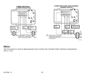
M10619 HEAT DAMPER HEAT RELAY COMPRESSOR CONTACTOR COOL DAMPER 1 POWER SUPPLY. 5-WIRE HEAT/COOL (JUMPER REMOVED) THERMOSTAT B RC O W Y R G 5-WIRE HEAT/COOL WITH DAMPER (JUMPER INTACT) THERMOSTAT B RC O W Y R G HEATING RELAY OR VALVE COIL 1 FAN RELAY COOLING CONTACTOR COIL 1 1 POWER SUPPLY. PROVIDE DISCONNECT MEANS AND OVERLOAD PROTECTION AS REQUIRED. PROVIDE DISCONNECT MEANS AND ...
M10619 HEAT DAMPER HEAT RELAY COMPRESSOR CONTACTOR COOL DAMPER 1 POWER SUPPLY. 5-WIRE HEAT/COOL (JUMPER REMOVED) THERMOSTAT B RC O W Y R G 5-WIRE HEAT/COOL WITH DAMPER (JUMPER INTACT) THERMOSTAT B RC O W Y R G HEATING RELAY OR VALVE COIL 1 FAN RELAY COOLING CONTACTOR COIL 1 1 POWER SUPPLY. PROVIDE DISCONNECT MEANS AND OVERLOAD PROTECTION AS REQUIRED. PROVIDE DISCONNECT MEANS AND ...


