
Owner's Manual
Page 1
MagicStat®/3355 Programmable Thermostat by Honeywell OWNER'S GUIDE Weekday/Weekend (5-day/ 2-day) Programmable Heat and/or Cool Low Voltage (20 to 30 Vac) Thermostat and Mounting Plate Model CT3355 1 6699--11001122
MagicStat®/3355 Programmable Thermostat by Honeywell OWNER'S GUIDE Weekday/Weekend (5-day/ 2-day) Programmable Heat and/or Cool Low Voltage (20 to 30 Vac) Thermostat and Mounting Plate Model CT3355 1 6699--11001122
Owner's Manual
Page 2
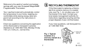
... waste management authority for instructions regarding recycling and the proper disposal of comfort and energy savings with your new Honeywell MagicStat® Programmable Thermostat. Fig. 1. MERCURY SWITCH M3701 2 69-1012 Direct any questions concerning the application of a mercury switch... Central time. Typical location of this thermostat to the instructions in this thermostat is replacing a thermostat that contains mercury in a sealed tube, see Fig. 1, do not place your home, keeping you have questions, call Honeywell Inc. If you comfortable while saving energy...
... waste management authority for instructions regarding recycling and the proper disposal of comfort and energy savings with your new Honeywell MagicStat® Programmable Thermostat. Fig. 1. MERCURY SWITCH M3701 2 69-1012 Direct any questions concerning the application of a mercury switch... Central time. Typical location of this thermostat to the instructions in this thermostat is replacing a thermostat that contains mercury in a sealed tube, see Fig. 1, do not place your home, keeping you have questions, call Honeywell Inc. If you comfortable while saving energy...
Owner's Manual
Page 3
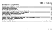
... Fan Operation Switch, as Required 18 Step 6: Adjust System On-Time, °F/C°, as Required 18 Step 7: Mount Thermostat Mounting Plate 21 Step 8: Wire Thermostat Terminals 23 Step 9: Mount Thermostat ...27 Step 10: Check Thermostat Operation After Programming and Installing 28 Step 11: Set Fan and System Switches 30 Troubleshooting Guide ...32 Limited One...
... Fan Operation Switch, as Required 18 Step 6: Adjust System On-Time, °F/C°, as Required 18 Step 7: Mount Thermostat Mounting Plate 21 Step 8: Wire Thermostat Terminals 23 Step 9: Mount Thermostat ...27 Step 10: Check Thermostat Operation After Programming and Installing 28 Step 11: Set Fan and System Switches 30 Troubleshooting Guide ...32 Limited One...
Owner's Manual
Page 4
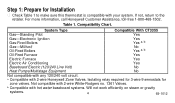
...with hot water baseboard systems. Will not work efficiently on steam or gravity systems. 4 69-1012 b Compatible with 2-wire Honeywell Zone Valves. Table 1. Compatibility Chart. Not compatible with any 120/240 volt circuit. System Type Compatible With CT3355 Gas-Standing ... No Not compatible with 2-wire White-Rodgers no. 1361 Valves. If not, return to make sure this thermostat is compatible with your system. Step 1: Prepare for zone valves. For more information, call Honeywell Customer Assistance, toll-free 1-800-468-1502. Isolating relay required for 3-wire...
...with hot water baseboard systems. Will not work efficiently on steam or gravity systems. 4 69-1012 b Compatible with 2-wire Honeywell Zone Valves. Table 1. Compatibility Chart. Not compatible with any 120/240 volt circuit. System Type Compatible With CT3355 Gas-Standing ... No Not compatible with 2-wire White-Rodgers no. 1361 Valves. If not, return to make sure this thermostat is compatible with your system. Step 1: Prepare for zone valves. For more information, call Honeywell Customer Assistance, toll-free 1-800-468-1502. Isolating relay required for 3-wire...
Owner's Manual
Page 5
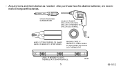
Also purchase two AA alkaline batteries; we recommend Energizer® batteries. CROSS-RECESSED SCREWDRIVER HAND OR POWER DRILL WITH 3/16 INCH DRILL BIT, IF NEEDED TO DRILL HOLES IN WALL WIRE CUTTER/STRIPPER OR SHARP KNIFE, IF NEEDED TO STRIP WIRES MASKING TAPE, IF NEEDED TO LABEL WIRES AS DISCONNECTED FROM OLD THERMOSTAT LEVEL, IF NEEDED TO LEVEL THERMOSTAT FOR APPEARANCE 5 M878B 69-1012 s Acquire tools and items below as needed.
Also purchase two AA alkaline batteries; we recommend Energizer® batteries. CROSS-RECESSED SCREWDRIVER HAND OR POWER DRILL WITH 3/16 INCH DRILL BIT, IF NEEDED TO DRILL HOLES IN WALL WIRE CUTTER/STRIPPER OR SHARP KNIFE, IF NEEDED TO STRIP WIRES MASKING TAPE, IF NEEDED TO LABEL WIRES AS DISCONNECTED FROM OLD THERMOSTAT LEVEL, IF NEEDED TO LEVEL THERMOSTAT FOR APPEARANCE 5 M878B 69-1012 s Acquire tools and items below as needed.
Owner's Manual
Page 6
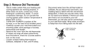
... system at the furnace, or at the fuse/circuit breaker panel. Wrap wires as shown to keep them from the old thermostat. s Carefully unpack your local heating/air conditioning dealer. As you will also not be labeled. WIRES THROUGH WALL OPENING M5136 6 69-1012 s Disconnect ... do not operate the cooling system when outdoor temperature is below 50°F (10°C). Step 2: Remove Old Thermostat s Test to make certain that is not connected to your old thermostat, you disconnect each wire, use masking tape to label it with the old terminal designation. If either does not ...
... system at the furnace, or at the fuse/circuit breaker panel. Wrap wires as shown to keep them from the old thermostat. s Carefully unpack your local heating/air conditioning dealer. As you will also not be labeled. WIRES THROUGH WALL OPENING M5136 6 69-1012 s Disconnect ... do not operate the cooling system when outdoor temperature is below 50°F (10°C). Step 2: Remove Old Thermostat s Test to make certain that is not connected to your old thermostat, you disconnect each wire, use masking tape to label it with the old terminal designation. If either does not ...
Owner's Manual
Page 7
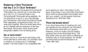
...terminals), you can operate the fan using electrical tape. If there are replacing a Honeywell Chronotherm® Thermostat, you probably have three thermostat wires. The thermostat is not compatible with your system, call Honeywell Customer Assistance at 1-800-468-1502. However, some hot water (zoned) heating systems... not interfere with your transformer. Do not allow them together. Replacing a Clock Thermostat that go to the C or C1 clock terminals on these systems. For details, call Honeywell Customer Assistance at 1-800-468-1502. 7 69-1012 If you have three wires...
...terminals), you can operate the fan using electrical tape. If there are replacing a Honeywell Chronotherm® Thermostat, you probably have three thermostat wires. The thermostat is not compatible with your system, call Honeywell Customer Assistance at 1-800-468-1502. However, some hot water (zoned) heating systems... not interfere with your transformer. Do not allow them together. Replacing a Clock Thermostat that go to the C or C1 clock terminals on these systems. For details, call Honeywell Customer Assistance at 1-800-468-1502. 7 69-1012 If you have three wires...
Owner's Manual
Page 8
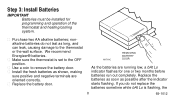
... the battery door. We recommend Energizer® batteries. s Install the fresh batteries as long, and can leak, causing damage to the thermostat or the wall surface. If you do not last as shown, making sure positive and negative terminals are running low, a bAt Lo indicator... flashes for programming and operation of the thermostat and heating/cooling system. s Purchase two AA alkaline batteries; nonalkaline batteries do not replace the batteries sometime while bAt Lo is set to...
... the battery door. We recommend Energizer® batteries. s Install the fresh batteries as long, and can leak, causing damage to the thermostat or the wall surface. If you do not last as shown, making sure positive and negative terminals are running low, a bAt Lo indicator... flashes for programming and operation of the thermostat and heating/cooling system. s Purchase two AA alkaline batteries; nonalkaline batteries do not replace the batteries sometime while bAt Lo is set to...
Owner's Manual
Page 9
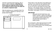
INSTALL TWO AA ALKALINE BATTERIES AS SHOWN M1713 Press down on without flashing, indicating the thermostat and heating/cooling system have to lack of removing the old ones, you leave to prevent the system from shutting down due to remove. After ... battery power. 9 69-1012 If you insert the new batteries within 20 to 30 seconds of battery power. indicator eventually stops flashing. IMPORTANT Although the thermostat has a low battery indicator, replace the batteries once a year to prevent the thermostat and heating/cooling system from shutting down due to reprogram the...
INSTALL TWO AA ALKALINE BATTERIES AS SHOWN M1713 Press down on without flashing, indicating the thermostat and heating/cooling system have to lack of removing the old ones, you leave to prevent the system from shutting down due to remove. After ... battery power. 9 69-1012 If you insert the new batteries within 20 to 30 seconds of battery power. indicator eventually stops flashing. IMPORTANT Although the thermostat has a low battery indicator, replace the batteries once a year to prevent the thermostat and heating/cooling system from shutting down due to reprogram the...
Owner's Manual
Page 10
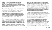
.... WAKE is the time period you want the house at a comfortable temperature for activities before bedtime. If you prefer to program the thermostat after it is the time period you can set for an energy-saving temperature while you are available during weekdays - Step 4: Program... Thermostat After the batteries are installed, the thermostat can be easily programmed in your hand, before it is the time period you want the house at a comfortable temperature when...
.... WAKE is the time period you want the house at a comfortable temperature for activities before bedtime. If you prefer to program the thermostat after it is the time period you can set for an energy-saving temperature while you are available during weekdays - Step 4: Program... Thermostat After the batteries are installed, the thermostat can be easily programmed in your hand, before it is the time period you want the house at a comfortable temperature when...
Owner's Manual
Page 11
...require it will set for an energy-saving temperature while you are available. For example, a house that is entered for the weekends, the thermostat will probably be different for each. Before programming, remove the clear plastic overlay covering the display. to give the furnace a head start to...the night.) You will automatically control heating at 68°F (20°C), and cooling at the step where you decide not to program the thermostat, it . Using sharp fingernails or pencil points can set one schedule for weekdays and another for weekends, because your finger or a soft ...
...require it will set for an energy-saving temperature while you are available. For example, a house that is entered for the weekends, the thermostat will probably be different for each. Before programming, remove the clear plastic overlay covering the display. to give the furnace a head start to...the night.) You will automatically control heating at 68°F (20°C), and cooling at the step where you decide not to program the thermostat, it . Using sharp fingernails or pencil points can set one schedule for weekdays and another for weekends, because your finger or a soft ...
Owner's Manual
Page 13
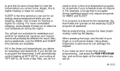
Weekdays WAKE 1 LEAVE RETURN 1 SLEEP Cooling Program Start Time 2 Heating Temperature Weekends WAKE 1 SLEEP 1 WAKE and RETURN start times should include extra lead time based on outside temperature and furnace response time, to give your furnace a head start to program the thermostat, it automatically controls heating at 68°F (20°C), and cooling at 78°F (26°C), 24 hours a day. 13 69-1012 NOTE: If you decide not to heat the house. 2 The temperatures cannot be set any higher than 88°F (31°C) or any lower than 45°F (7°C).
Weekdays WAKE 1 LEAVE RETURN 1 SLEEP Cooling Program Start Time 2 Heating Temperature Weekends WAKE 1 SLEEP 1 WAKE and RETURN start times should include extra lead time based on outside temperature and furnace response time, to give your furnace a head start to program the thermostat, it automatically controls heating at 68°F (20°C), and cooling at 78°F (26°C), 24 hours a day. 13 69-1012 NOTE: If you decide not to heat the house. 2 The temperatures cannot be set any higher than 88°F (31°C) or any lower than 45°F (7°C).
Owner's Manual
Page 14
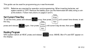
.../Day once, then press until M1699A current day shows; Back M1699A Heating Program With system switch at the bottom. Remove the battery door (on the thermostat left side) using a coin at HEAT, press and release Weekday Schedule once. then press Run Program . to OFF. NOTE: Batteries are required for programming your...
.../Day once, then press until M1699A current day shows; Back M1699A Heating Program With system switch at the bottom. Remove the battery door (on the thermostat left side) using a coin at HEAT, press and release Weekday Schedule once. then press Run Program . to OFF. NOTE: Batteries are required for programming your...
Owner's Manual
Page 18
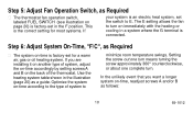
... on-time, readjust screws A and/or B as a guide. Optimize the system on-time according to E. Step 6: Adjust System On-Time, °F/C°, as Required s The thermostat fan operation switch, labeled FUEL SWITCH (see illustration on page 20) is factory-set the switch to the type of the... thermostat. In the unlikely event that you are installing it on another type of system, adjust the on-time accordingly by setting screws A and B on the ...
... on-time, readjust screws A and/or B as a guide. Optimize the system on-time according to E. Step 6: Adjust System On-Time, °F/C°, as Required s The thermostat fan operation switch, labeled FUEL SWITCH (see illustration on page 20) is factory-set the switch to the type of the... thermostat. In the unlikely event that you are installing it on another type of system, adjust the on-time accordingly by setting screws A and B on the ...
Owner's Manual
Page 19
IMPORTANT When using a high efficiency furnace such as shown in degrees Fahrenheit. NOTE: This thermostat does not have a setting for accurate temperature control. Cycles would not be long enough for steam/gravity air. First, turn in both screws completely, then ..., adjust screw C out one turn, as a 90% or greater AFUE (Average Fuel Utilization Efficiency) unit, adjust screw A out one turn and leave screw B in ). s The thermostat is set to read the temperature in illustration. 19 69-1012
IMPORTANT When using a high efficiency furnace such as shown in degrees Fahrenheit. NOTE: This thermostat does not have a setting for accurate temperature control. Cycles would not be long enough for steam/gravity air. First, turn in both screws completely, then ..., adjust screw C out one turn, as a 90% or greater AFUE (Average Fuel Utilization Efficiency) unit, adjust screw A out one turn and leave screw B in ). s The thermostat is set to read the temperature in illustration. 19 69-1012
Owner's Manual
Page 20
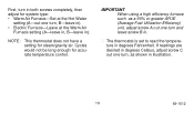
F POSITION FUEL SWITCH F E C ADJUST SCREWS THROUGH HOLES TO SELECT OPERATION DESIRED HEATING SYSTEM FUEL SWITCH POSITION D WARM AIR A-IN B-IN F FURNACE HOT WATER A-OUT B-IN F BOILER 1 TURN ELECTRIC A-IN B-OUT E FURNACE 1 TURN W Y G R Rc M8796 20 69-1012 THERMOSTAT BACK A DISPLAY °F C-IN DISPLAY °C C-OUT 1 TURN B FOR HIGH EFFICIENCY FURNACE (90%+ AFUE) ADJUST: SCREW A-OUT ONE TURN SCREW B-IN FUEL SWITCH -
F POSITION FUEL SWITCH F E C ADJUST SCREWS THROUGH HOLES TO SELECT OPERATION DESIRED HEATING SYSTEM FUEL SWITCH POSITION D WARM AIR A-IN B-IN F FURNACE HOT WATER A-OUT B-IN F BOILER 1 TURN ELECTRIC A-IN B-OUT E FURNACE 1 TURN W Y G R Rc M8796 20 69-1012 THERMOSTAT BACK A DISPLAY °F C-IN DISPLAY °C C-OUT 1 TURN B FOR HIGH EFFICIENCY FURNACE (90%+ AFUE) ADJUST: SCREW A-OUT ONE TURN SCREW B-IN FUEL SWITCH -
Owner's Manual
Page 21
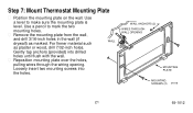
... the wiring opening. WALL ANCHORS (2) WIRES THROUGH WALL OPENING MOUNTING PLATE MOUNTING SCREWS (2) M1718 21 69-1012 For firmer material such as marked. Step 7: Mount Thermostat Mounting Plate s Position the mounting plate on the wall. Loosely insert two mounting screws into drilled holes until flush with the wall. Use a pencil to...
... the wiring opening. WALL ANCHORS (2) WIRES THROUGH WALL OPENING MOUNTING PLATE MOUNTING SCREWS (2) M1718 21 69-1012 For firmer material such as marked. Step 7: Mount Thermostat Mounting Plate s Position the mounting plate on the wall. Loosely insert two mounting screws into drilled holes until flush with the wall. Use a pencil to...
Owner's Manual
Page 22
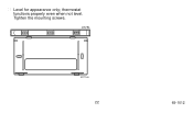
Tighten the mounting screws. LEVEL M1714A 22 69-1012 s Level for appearance only; thermostat functions properly even when not level.
Tighten the mounting screws. LEVEL M1714A 22 69-1012 s Level for appearance only; thermostat functions properly even when not level.
Owner's Manual
Page 23
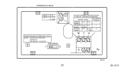
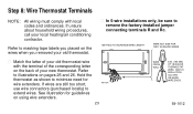
... shown to minimize need for guidelines on using wire extenders. 23 WIRE FROM WALL 6 IN. (152 MM) OF 18-GAUGE THERMOSTAT WIRE. s In 5-wire installations only, be sure to illustrations on pages 25 and 26. MATCH INSULATION COLORS OR MARK WIRE ENDS. 69-1012 Refer to ...extend wires. METHOD TO INCREASE WIRE LENGTH WIRE NUT SIZE FOR TWO 18-GAUGE WIRES s Match the letter of your new thermostat. Refer to remove the factory-installed jumper connecting terminals R and Rc. If unsure about household wiring procedures, call your old...
... shown to minimize need for guidelines on using wire extenders. 23 WIRE FROM WALL 6 IN. (152 MM) OF 18-GAUGE THERMOSTAT WIRE. s In 5-wire installations only, be sure to illustrations on pages 25 and 26. MATCH INSULATION COLORS OR MARK WIRE ENDS. 69-1012 Refer to ...extend wires. METHOD TO INCREASE WIRE LENGTH WIRE NUT SIZE FOR TWO 18-GAUGE WIRES s Match the letter of your new thermostat. Refer to remove the factory-installed jumper connecting terminals R and Rc. If unsure about household wiring procedures, call your old...
Owner's Manual
Page 24
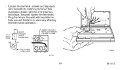
Securely tighten the terminals. s Plug the hole in the wall with insulation to help prevent drafts from adversely affecting the thermostat operation. 5/16 in. (8 mm) STRIP INSERT STRAIGHT UNDER SCREW HEAD Rc JUMPER (FACTORYINSTALLED) REMOVE IF 5-WIRE SYSTEM R END OF WIRE VISIBLE HERE WY G M1712A 24 M3002A 69-1012 See illustration (lower right) for wire insertion technique. s Loosen the terminal screws and slip each wire beneath its matching terminal.
Securely tighten the terminals. s Plug the hole in the wall with insulation to help prevent drafts from adversely affecting the thermostat operation. 5/16 in. (8 mm) STRIP INSERT STRAIGHT UNDER SCREW HEAD Rc JUMPER (FACTORYINSTALLED) REMOVE IF 5-WIRE SYSTEM R END OF WIRE VISIBLE HERE WY G M1712A 24 M3002A 69-1012 See illustration (lower right) for wire insertion technique. s Loosen the terminal screws and slip each wire beneath its matching terminal.


