
Owner's Manual
Page 24
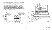
See illustration (lower right) for wire insertion technique. s Plug the hole in the wall with insulation to help prevent drafts from adversely affecting the thermostat operation. 5/16 in. (8 mm) STRIP INSERT STRAIGHT UNDER SCREW HEAD Rc JUMPER (FACTORYINSTALLED) REMOVE IF 5-WIRE SYSTEM R END OF WIRE VISIBLE HERE WY G M1712A 24 M3002A 69-1012 s Loosen the terminal screws and slip each wire beneath its matching terminal. Securely tighten the terminals.
See illustration (lower right) for wire insertion technique. s Plug the hole in the wall with insulation to help prevent drafts from adversely affecting the thermostat operation. 5/16 in. (8 mm) STRIP INSERT STRAIGHT UNDER SCREW HEAD Rc JUMPER (FACTORYINSTALLED) REMOVE IF 5-WIRE SYSTEM R END OF WIRE VISIBLE HERE WY G M1712A 24 M3002A 69-1012 s Loosen the terminal screws and slip each wire beneath its matching terminal. Securely tighten the terminals.