Instruction Manual
Page 7
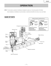
... Manual is designed to assist you in this Manual may show details or attachments that differ from those on your own Nailer. Some illustrations in the safe operation of the valve part Exhaust Cover Valve Bush Switching Device Valve Bush Switching Device SINGLE... MECHANISM (Switching device: upward position) CONTACT ACTUATION MECHANISM (Switching device: downward position) Piston Piston O-Ring Driver Blade Nose Adjuster [ ] Only NR83A2 (with depth adjustment) Push Lever Valve part Trigger Switching Device Valve Bush Body Cap Air Plug (Sold separetely) Ribbon Spring Stop Lever Nail ...
... Manual is designed to assist you in this Manual may show details or attachments that differ from those on your own Nailer. Some illustrations in the safe operation of the valve part Exhaust Cover Valve Bush Switching Device Valve Bush Switching Device SINGLE... MECHANISM (Switching device: upward position) CONTACT ACTUATION MECHANISM (Switching device: downward position) Piston Piston O-Ring Driver Blade Nose Adjuster [ ] Only NR83A2 (with depth adjustment) Push Lever Valve part Trigger Switching Device Valve Bush Body Cap Air Plug (Sold separetely) Ribbon Spring Stop Lever Nail ...
Instruction Manual
Page 10
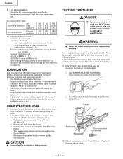
... any screws are loose, tighten them. Ⅺ THE PUSH LEVER AND TRIGGER MUST MOVE SMOOTHLY. Without proper lubrication, the Nailer will wear prematurely. ⅜ Use Hitachi pneumatic tool lubricant. Keep the lubricator filled with side shields which conforms to warm up the moving part. CAUTION ⅷ ...) After making the calculations as shown above, you should always be used. Trigger Push Lever Do not connect air hose (2) Adjust the air pressure to freefire the Nailer. Conduct the tests in a cold weather environment. This will harm the O-rings and other rubber parts.
... any screws are loose, tighten them. Ⅺ THE PUSH LEVER AND TRIGGER MUST MOVE SMOOTHLY. Without proper lubrication, the Nailer will wear prematurely. ⅜ Use Hitachi pneumatic tool lubricant. Keep the lubricator filled with side shields which conforms to warm up the moving part. CAUTION ⅷ ...) After making the calculations as shown above, you should always be used. Trigger Push Lever Do not connect air hose (2) Adjust the air pressure to freefire the Nailer. Conduct the tests in a cold weather environment. This will harm the O-rings and other rubber parts.
Instruction Manual
Page 11
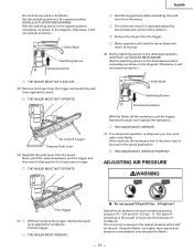
... the trigger. Depress the push lever against the workpiece. Ⅺ THE NAILER MUST OPERATE. (7) If no abnormal operation is the same type to the downward position completely as shown in the Nailer. ADJUSTING AIR PRESSURE WARNING Pull Trigger (5) 1 Without touching the trigger, depress the... - 8.3 bar 5 - 8.5 kgf/cm2) according to the upward position completely as shown in the actual application. Ⅺ THE NAILER MUST OPERATE PROPERLY. Adjust the air pressure at the bottom). 3 Remove the finger from the wood. Otherwise, it will not operate properly.) Valve Bush Switching ...
... the trigger. Depress the push lever against the workpiece. Ⅺ THE NAILER MUST OPERATE. (7) If no abnormal operation is the same type to the downward position completely as shown in the Nailer. ADJUSTING AIR PRESSURE WARNING Pull Trigger (5) 1 Without touching the trigger, depress the... - 8.3 bar 5 - 8.5 kgf/cm2) according to the upward position completely as shown in the actual application. Ⅺ THE NAILER MUST OPERATE PROPERLY. Adjust the air pressure at the bottom). 3 Remove the finger from the wood. Otherwise, it will not operate properly.) Valve Bush Switching ...
Instruction Manual
Page 15
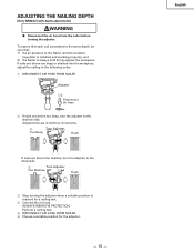
... is installed and working properly), and 2) the Nailer is reached for the adjuster. - 15 - ADJUSTING THE NAILING DEPTH [Only NR83A2 (with depth adjustment)] WARNING ⅷ Disconnect the air hose from the nailer before turning the adjuster. ALWAYS WEAR EYE PROTECTION. Adjustments are in the following order. 1 DISCONNECT AIR HOSE FROM NAILER Adjuster 15 Disconnect air hose 2 If nails are driven...
... is installed and working properly), and 2) the Nailer is reached for the adjuster. - 15 - ADJUSTING THE NAILING DEPTH [Only NR83A2 (with depth adjustment)] WARNING ⅷ Disconnect the air hose from the nailer before turning the adjuster. ALWAYS WEAR EYE PROTECTION. Adjustments are in the following order. 1 DISCONNECT AIR HOSE FROM NAILER Adjuster 15 Disconnect air hose 2 If nails are driven...
Instruction Manual
Page 17
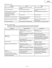
... line filter daily. Clean filter element - HOW Open manual petcock. Open petcock on air compressor tank. If problems persist, contact a Hitachi authorized service center for a jam. PROBLEM Nailer operates, but does not drive fully at faster nailing speeds. CHECK METHOD Check for assistance. Ribbon spring weakend or damaged? --- Driver ... function of moisture and dirt. Piston O-ring cut or heavily worn? CORRECTION Clear a jam. Clean and lubricate. Replace ribbon spring. Reduce air pressure. (Adjust 70 - 120 psi) Use only recommended nails. Clean and lubricate. Contact...
... line filter daily. Clean filter element - HOW Open manual petcock. Open petcock on air compressor tank. If problems persist, contact a Hitachi authorized service center for a jam. PROBLEM Nailer operates, but does not drive fully at faster nailing speeds. CHECK METHOD Check for assistance. Ribbon spring weakend or damaged? --- Driver ... function of moisture and dirt. Piston O-ring cut or heavily worn? CORRECTION Clear a jam. Clean and lubricate. Replace ribbon spring. Reduce air pressure. (Adjust 70 - 120 psi) Use only recommended nails. Clean and lubricate. Contact...
Parts List
Page 2
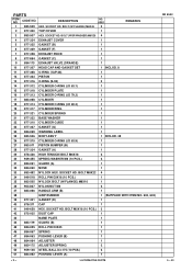
...-025 ROLL PIN D3X45 1 46 884-067 SPRING 1 47 884-063 PUSHING LEVER (B) 1 48 884-064 ADJUSTER 1 49 880-175 ADJUSTER SPRING 2 50 959-148 STEEL BALL D3.175 (10 PCS.) 2 51 884-062 PUSHING LEVER (A) 1...(F) 1 7 877-328 EXHAUST PIECE 1 8 877-854 GASKET (C) 1 9 884-110 EXHAUST VALVE (ORANGE) 1 10 877-307 HEAD CAP AND GASKET SET 1 INCLUD. 8 11 877-368 O-RING (1AP-48) 1 12 877-323 PISTON 1 13 877-316 ... 1 22 877-310 CYLINDER GUIDE 1 23 877-327 GASKET (G) 1 24 884-069 WARNING LABEL 1 25 883-506 BODY ASS'Y 1 INCLUD. 38 26 877-315 CYLINDER O-RING (I.D 63.9) 1 27 883-...
...-025 ROLL PIN D3X45 1 46 884-067 SPRING 1 47 884-063 PUSHING LEVER (B) 1 48 884-064 ADJUSTER 1 49 880-175 ADJUSTER SPRING 2 50 959-148 STEEL BALL D3.175 (10 PCS.) 2 51 884-062 PUSHING LEVER (A) 1...(F) 1 7 877-328 EXHAUST PIECE 1 8 877-854 GASKET (C) 1 9 884-110 EXHAUST VALVE (ORANGE) 1 10 877-307 HEAD CAP AND GASKET SET 1 INCLUD. 8 11 877-368 O-RING (1AP-48) 1 12 877-323 PISTON 1 13 877-316 ... 1 22 877-310 CYLINDER GUIDE 1 23 877-327 GASKET (G) 1 24 884-069 WARNING LABEL 1 25 883-506 BODY ASS'Y 1 INCLUD. 38 26 877-315 CYLINDER O-RING (I.D 63.9) 1 27 883-...


