Instruction Manual
Page 3
... that result from the operation and maintenance of this Manual and in this nailer. Never use this Manual. DEFINITIONS OF SIGNAL WORDS DANGER indicates an imminently hazardous situation which contain the operation and maintenance instructions. First, pull the trigger; next, press the push lever against the wood; next, pull the trigger to drive the nail. First, pull the trigger; If the trigger is released and pressed again...
... that result from the operation and maintenance of this Manual and in this nailer. Never use this Manual. DEFINITIONS OF SIGNAL WORDS DANGER indicates an imminently hazardous situation which contain the operation and maintenance instructions. First, pull the trigger; next, press the push lever against the wood; next, pull the trigger to drive the nail. First, pull the trigger; If the trigger is released and pressed again...
Instruction Manual
Page 4
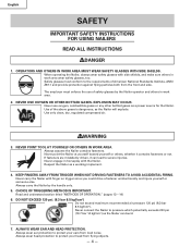
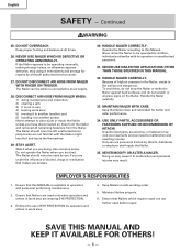
... air pressure 120 psi (8.3 bar 8.5 kgf/cm2). NEVER POINT TOOL AT YOURSELF OR OTHERS IN WORK AREA. CHOICE OF TRIGGERING METHOD IS IMPORTANT. Always assume the Nailer contains fasteners. Safety glasses must enforce the use oxygen, combustible gases or any other bottled gases as a working implement. 4. English SAFETY IMPORTANT SAFETY INSTRUCTIONS MMMMFOR USING NAILERSMMlMM READ ALL INSTRUCTIONS DANGER 1. OPERATORS AND OTHERS IN WORK AREA MUST WEAR SAFETY...
... air pressure 120 psi (8.3 bar 8.5 kgf/cm2). NEVER POINT TOOL AT YOURSELF OR OTHERS IN WORK AREA. CHOICE OF TRIGGERING METHOD IS IMPORTANT. Always assume the Nailer contains fasteners. Safety glasses must enforce the use oxygen, combustible gases or any other bottled gases as a working implement. 4. English SAFETY IMPORTANT SAFETY INSTRUCTIONS MMMMFOR USING NAILERSMMlMM READ ALL INSTRUCTIONS DANGER 1. OPERATORS AND OTHERS IN WORK AREA MUST WEAR SAFETY...
Instruction Manual
Page 5
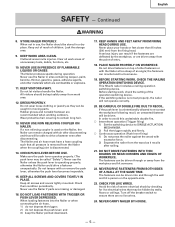
... OF FLAMMABLE LIQUIDS OR GASES. Do not let visitors handle the Nailer. NEVER USE NON RELIEVING COUPLER ON NAILER. CHECK PUSH LEVER BEFORE USE. A serious injury can ricochet and hurt someone . 22. BEFORE STARTING WORK, CHECK THE NAILING OPERATION SWITCHING DEVICE. Before starting work areas of the operation switching device. CHECK FOR LIVE WIRES. Turn off the breaker switch to re-contact the workpiece following recoil, an unwanted...
... OF FLAMMABLE LIQUIDS OR GASES. Do not let visitors handle the Nailer. NEVER USE NON RELIEVING COUPLER ON NAILER. CHECK PUSH LEVER BEFORE USE. A serious injury can ricochet and hurt someone . 22. BEFORE STARTING WORK, CHECK THE NAILING OPERATION SWITCHING DEVICE. Before starting work areas of the operation switching device. CHECK FOR LIVE WIRES. Turn off the breaker switch to re-contact the workpiece following recoil, an unwanted...
Instruction Manual
Page 6
Continued WARNING 25. NEVER USE NAILER WHICH IS DEFECTIVE OR OPERATING ABNORMALLY. DO NOT DISCONNECT AIR HOSE FROM NAILER WITH FINGER ON TRIGGER. Watch what you are wearing EYE PROTECTION. 3. To avoid this MANUAL is not in work area are tired. Keep the Nailer clean and lubricated for repairs by a Hitachi authorized service center. 27. Unauthorized parts, accessories, or fasteners may result. Ensure that Nailers are not familiar...
Continued WARNING 25. NEVER USE NAILER WHICH IS DEFECTIVE OR OPERATING ABNORMALLY. DO NOT DISCONNECT AIR HOSE FROM NAILER WITH FINGER ON TRIGGER. Watch what you are wearing EYE PROTECTION. 3. To avoid this MANUAL is not in work area are tired. Keep the Nailer clean and lubricated for repairs by a Hitachi authorized service center. 27. Unauthorized parts, accessories, or fasteners may result. Ensure that Nailers are not familiar...
Instruction Manual
Page 7
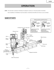
...) Piston Piston O-Ring Driver Blade Nose Adjuster [ ] Only NR83A2 (with depth adjustment) Push Lever Valve part Trigger Switching Device Valve Bush Body Cap Air Plug (Sold separetely) Ribbon Spring Stop Lever Nail Feeder Magazine Assembly Outlet (Firing Head) - 7 - English OPERATION NOTE: The information contained in this Manual is designed to assist you in this Manual may show details or attachments that differ from those on your own Nailer. NAME OF PARTS Nailing operation switching device Enlarged view...
...) Piston Piston O-Ring Driver Blade Nose Adjuster [ ] Only NR83A2 (with depth adjustment) Push Lever Valve part Trigger Switching Device Valve Bush Body Cap Air Plug (Sold separetely) Ribbon Spring Stop Lever Nail Feeder Magazine Assembly Outlet (Firing Head) - 7 - English OPERATION NOTE: The information contained in this Manual is designed to assist you in this Manual may show details or attachments that differ from those on your own Nailer. NAME OF PARTS Nailing operation switching device Enlarged view...
Instruction Manual
Page 8
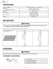
... can be driven with this Nailer. STANDARD ACCESSORIES 1 Eye protection 1 2 Allen wrench for M8 screw 1 3 Allen wrench for M6 screw 1 1 23 4 4 Allen wrench for the NR83A2/NR83A2(S). Only nails shown in tool malfunction and/or nail breakdown, leading to malfunction and resulting injuries. The use only the genuine HITACHI nails for M5 screw 1 - 8 - English SPECIFICATIONS Operating pressure Dimensions Length × Height × Width Weight Nail capacity Air consumption Air inlet 70 - 120 psi (4.9 - 8.3 bar...
... can be driven with this Nailer. STANDARD ACCESSORIES 1 Eye protection 1 2 Allen wrench for M8 screw 1 3 Allen wrench for M6 screw 1 1 23 4 4 Allen wrench for the NR83A2/NR83A2(S). Only nails shown in tool malfunction and/or nail breakdown, leading to malfunction and resulting injuries. The use only the genuine HITACHI nails for M5 screw 1 - 8 - English SPECIFICATIONS Operating pressure Dimensions Length × Height × Width Weight Nail capacity Air consumption Air inlet 70 - 120 psi (4.9 - 8.3 bar...
Instruction Manual
Page 9
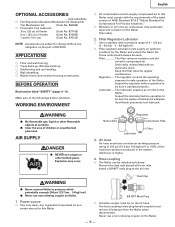
...: Remove the dust seal placed at the air inlet. sold separately ⅜ Full Sequential Actuation Mechanism kit (Sequential Trip Mechanism kit) (Code No. 884069) ⅜ Pneumatic Tool Lubricant .8 oz. (25 cc) oil feeder (Code No. 877153) 4 oz. (120 cc) oil feeder (Code No. 874042) 1 quart (1 ltr) can be sure it operates properly. Keep the filter clean by regular maintenance. The lubricator supplies an oil mist to change...
...: Remove the dust seal placed at the air inlet. sold separately ⅜ Full Sequential Actuation Mechanism kit (Sequential Trip Mechanism kit) (Code No. 884069) ⅜ Pneumatic Tool Lubricant .8 oz. (25 cc) oil feeder (Code No. 877153) 4 oz. (120 cc) oil feeder (Code No. 874042) 1 quart (1 ltr) can be sure it operates properly. Keep the filter clean by regular maintenance. The lubricator supplies an oil mist to change...
Instruction Manual
Page 10
... not free-fire the Nailer at 100 psi driving 30 nails per Nailer × air consumption at given air pressure × safety factor (always 1.2) Example: 2 Nailers operating at high pressure. WARNING ⅷ Never use detergent oil or additives. REMOVE ALL NAILS FROM NAILER. Ⅺ ALL SCREWS MUST BE TIGHTENED. Connect the air hose. - 10 - Air consumption Using the Air consumption table and the Air compressor size formula, find a compressor providing 6.3 CFM of air that the Nailer be used. If abnormal operation occurs, stop using the...
... not free-fire the Nailer at 100 psi driving 30 nails per Nailer × air consumption at given air pressure × safety factor (always 1.2) Example: 2 Nailers operating at high pressure. WARNING ⅷ Never use detergent oil or additives. REMOVE ALL NAILS FROM NAILER. Ⅺ ALL SCREWS MUST BE TIGHTENED. Connect the air hose. - 10 - Air consumption Using the Air consumption table and the Air compressor size formula, find a compressor providing 6.3 CFM of air that the Nailer be used. If abnormal operation occurs, stop using the...
Instruction Manual
Page 11
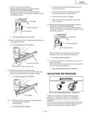
... Do not load any nails in the diagram. Valve Bush Switching Device Downward position Do not pull Trigger Depress Push Lever (4) Separate the push lever from the trigger. Ⅺ Nailer operation will end (the driver blade will do the job. Using the Nailer at recommended operating pressure 70 - 120 psi (4.9 - 8.3 bar 5 - 8.5 kgf/cm2) according to the downward position completely as shown in the Nailer. Set the switching device to the...
... Do not load any nails in the diagram. Valve Bush Switching Device Downward position Do not pull Trigger Depress Push Lever (4) Separate the push lever from the trigger. Ⅺ Nailer operation will end (the driver blade will do the job. Using the Nailer at recommended operating pressure 70 - 120 psi (4.9 - 8.3 bar 5 - 8.5 kgf/cm2) according to the downward position completely as shown in the Nailer. Set the switching device to the...
Instruction Manual
Page 12
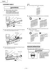
.... Nail Strip ⅷ Ensure that the head of tail nail is now ready to ANSI Z87.1 specifications. - 12 - NAILER OPERATION Read section titled "SAFETY"(pages 4 - 6). English LOADING NAILS WARNING ⅷ When loading nails into Nailer, 1) do not depress trigger; 2) do not depress push lever; Nail Feeder NOTE: ⅷ Use nail strip at one from above the magazine. Stop Lever Nail Feeder The Nailer is set under the nail stopper of nails overlapped as shown in work area...
.... Nail Strip ⅷ Ensure that the head of tail nail is now ready to ANSI Z87.1 specifications. - 12 - NAILER OPERATION Read section titled "SAFETY"(pages 4 - 6). English LOADING NAILS WARNING ⅷ When loading nails into Nailer, 1) do not depress trigger; 2) do not depress push lever; Nail Feeder NOTE: ⅷ Use nail strip at one from above the magazine. Stop Lever Nail Feeder The Nailer is set under the nail stopper of nails overlapped as shown in work area...
Instruction Manual
Page 13
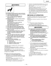
... in work , make sure that the SINGLE ACTUATION MECHANISM of this Nailer. First, pull the trigger; First, pull the trigger; There are : 1. This Hitachi nailer is depressed (upward position). Continuous operation (Push lever fire): (1) Intermittent operation (Trigger fire) Use the SINGLE ACTUATION MECHANISM setting. Part no. 884069. nails can be set to SINGLE ACTUATION MECHANISM). (Set the switching device to the upward position completely as hammer. ⅷ Disconnect air hose...
... in work , make sure that the SINGLE ACTUATION MECHANISM of this Nailer. First, pull the trigger; First, pull the trigger; There are : 1. This Hitachi nailer is depressed (upward position). Continuous operation (Push lever fire): (1) Intermittent operation (Trigger fire) Use the SINGLE ACTUATION MECHANISM setting. Part no. 884069. nails can be set to SINGLE ACTUATION MECHANISM). (Set the switching device to the upward position completely as hammer. ⅷ Disconnect air hose...
Instruction Manual
Page 14
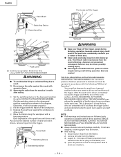
... the workpiece to drive a nail. 4 Move the Nailer along the workpiece with a bouncing motion. Exercise caution! This is because it is driven, completely release the trigger and lift the tool off the workpiece. 3 Depress the push lever against yourself or others in the diagram. English Valve Bush Previously pull the trigger Switching Device 1 Upward position 2 4 Trigger 4 3 Push Lever (2) Continuous operation (Push lever fire) Using CONTACT ACTUATION...
... the workpiece to drive a nail. 4 Move the Nailer along the workpiece with a bouncing motion. Exercise caution! This is because it is driven, completely release the trigger and lift the tool off the workpiece. 3 Depress the push lever against yourself or others in the diagram. English Valve Bush Previously pull the trigger Switching Device 1 Upward position 2 4 Trigger 4 3 Push Lever (2) Continuous operation (Push lever fire) Using CONTACT ACTUATION...
Instruction Manual
Page 15
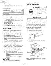
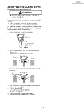
ADJUSTING THE NAILING DEPTH [Only NR83A2 (with depth adjustment)] WARNING ⅷ Disconnect the air hose from the nailer before turning the adjuster. Perform a nailing test. 5 DISCONNECT AIR HOSE FROM NAILER. 6 Choose a suitable position for a nailing test. 4 Connect the air hose. ALWAYS WEAR EYE PROTECTION. Adjustments are in the following order. 1 DISCONNECT AIR HOSE FROM NAILER Adjuster 15 Disconnect air hose 2 If nails are driven too shallow, turn the adjuster to the Nailer remains constant (regulator is installed and working properly), and 2) the...
ADJUSTING THE NAILING DEPTH [Only NR83A2 (with depth adjustment)] WARNING ⅷ Disconnect the air hose from the nailer before turning the adjuster. Perform a nailing test. 5 DISCONNECT AIR HOSE FROM NAILER. 6 Choose a suitable position for a nailing test. 4 Connect the air hose. ALWAYS WEAR EYE PROTECTION. Adjustments are in the following order. 1 DISCONNECT AIR HOSE FROM NAILER Adjuster 15 Disconnect air hose 2 If nails are driven too shallow, turn the adjuster to the Nailer remains constant (regulator is installed and working properly), and 2) the...
Instruction Manual
Page 16
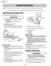
... use. Operator troubleshooting (See page 17) Nail Feeder Magazine 1 Disconnect air hose CAUTION ⅷ Check that differ from a Hitachi authorized service center. 6. In the operation and maintenance of HITACHI. - 16 - MAINTENANCE AND INSPECTION Read section titled "SAFETY" (pages 4 - 6). WARNING ⅷ Disconnect air hose and remove all nails from Nailer when: 1) doing maintenance and inspection; Service parts list A: Item No. This Parts List will eventually require servicing or replacement of parts because of the Nailer. SERVICE AND REPAIRS WARNING ⅷ Only service...
... use. Operator troubleshooting (See page 17) Nail Feeder Magazine 1 Disconnect air hose CAUTION ⅷ Check that differ from a Hitachi authorized service center. 6. In the operation and maintenance of HITACHI. - 16 - MAINTENANCE AND INSPECTION Read section titled "SAFETY" (pages 4 - 6). WARNING ⅷ Disconnect air hose and remove all nails from Nailer when: 1) doing maintenance and inspection; Service parts list A: Item No. This Parts List will eventually require servicing or replacement of parts because of the Nailer. SERVICE AND REPAIRS WARNING ⅷ Only service...
Instruction Manual
Page 17
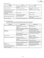
... using the table below. Driver blade worn? Piston O-ring worn or damaged? Check function of filter with Hitachi pneumatic tool lubricant. Replace ribbon spring. WHY Prevent accumulation of lubricant into the Nailer. Slow to normal flow. Nails jam. Check function of air hose. Ribbon spring weakend or damaged? --- Follow manufacturer's instructions. CHECK METHOD Check for replacement. Check air pressure. --- Replace ribbon spring. Clean filter element - Keep push lever working properly. Promote operator safety...
... using the table below. Driver blade worn? Piston O-ring worn or damaged? Check function of filter with Hitachi pneumatic tool lubricant. Replace ribbon spring. WHY Prevent accumulation of lubricant into the Nailer. Slow to normal flow. Nails jam. Check function of air hose. Ribbon spring weakend or damaged? --- Follow manufacturer's instructions. CHECK METHOD Check for replacement. Check air pressure. --- Replace ribbon spring. Clean filter element - Keep push lever working properly. Promote operator safety...
Instruction Manual
Page 52
Norcross, GA 30093 Hitachi Koki Canada Co. 6395 Kestrel Road Mississauga ON L5T 1Z5 308 Code No. Issued by Hitachi Koki U.S.A., Ltd. 3950 Steve Reynolds Blvd. C99118963 N Printed in Japan Shinagawa Intercity Tower A, 15-1, Konan 2-chome, Minato-ku, Tokyo 108-6020, Japan Distributed by Hitachi Koki Co., Ltd.
Norcross, GA 30093 Hitachi Koki Canada Co. 6395 Kestrel Road Mississauga ON L5T 1Z5 308 Code No. Issued by Hitachi Koki U.S.A., Ltd. 3950 Steve Reynolds Blvd. C99118963 N Printed in Japan Shinagawa Intercity Tower A, 15-1, Konan 2-chome, Minato-ku, Tokyo 108-6020, Japan Distributed by Hitachi Koki Co., Ltd.
Parts List
Page 2
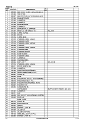
...-035 DUST CAP 1 43 NAME PLATE 1 44 884-119 GUARD (B) 1 45 884-025 ROLL PIN D3X45 1 46 884-067 SPRING 1 47 884-063 PUSHING LEVER (B) 1 48 884-064 ADJUSTER 1 49 880-175 ADJUSTER SPRING 2 50 959-148 STEEL BALL D3.175 (10 PCS.) 2 51 884-062 PUSHING LEVER (A) 1 --- 2 --- * ALTERNATIVE PARTS NR 83A2 5 -- 03 BOLT (W/FLANGE) M6X45 NO. SOCKET HD. BOLT (W/SP.WASHER...
...-035 DUST CAP 1 43 NAME PLATE 1 44 884-119 GUARD (B) 1 45 884-025 ROLL PIN D3X45 1 46 884-067 SPRING 1 47 884-063 PUSHING LEVER (B) 1 48 884-064 ADJUSTER 1 49 880-175 ADJUSTER SPRING 2 50 959-148 STEEL BALL D3.175 (10 PCS.) 2 51 884-062 PUSHING LEVER (A) 1 --- 2 --- * ALTERNATIVE PARTS NR 83A2 5 -- 03 BOLT (W/FLANGE) M6X45 NO. SOCKET HD. BOLT (W/SP.WASHER...
Parts List
Page 3
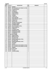
... 1 O-RING (S-12) 1 VALVE PLATE 1 TRIGGER VALVE BUSHING 1 TRIGGER PLUNGER 1 PLUNGER O-RING 1 ROLL PIN D3X30 (10 PCS.) 1 VALVE SLEEVE (A) 1 O-RING (S-7) 1 PLUNGER O-RING 1 WASHER M5 (10 PCS.) 1 PLUNGER (B) SPRING 1 PLUNGER (B) 1 NAIL FEEDER 1 RIBBON SPRING 1 NEEDLE ROLLER 1 NYLON NUT M4 1 SPRING WASHER M4 (10 PCS.) 1 NYLON NUT M5 1 SPRING WASHER M5 (10 PCS.) 1 MAGAZINE 1 SLEEVE 1 HEX. BOLT M4X15 (10 PCS.) 1 WASHER 1 STOP LEVER 1 COLLAR 1 STOPPER SPRING 1 REMARKS NR 83A2 5 -- 03 * ALTERNATIVE PARTS --- 3 --- CODE NO. 52 880...
... 1 O-RING (S-12) 1 VALVE PLATE 1 TRIGGER VALVE BUSHING 1 TRIGGER PLUNGER 1 PLUNGER O-RING 1 ROLL PIN D3X30 (10 PCS.) 1 VALVE SLEEVE (A) 1 O-RING (S-7) 1 PLUNGER O-RING 1 WASHER M5 (10 PCS.) 1 PLUNGER (B) SPRING 1 PLUNGER (B) 1 NAIL FEEDER 1 RIBBON SPRING 1 NEEDLE ROLLER 1 NYLON NUT M4 1 SPRING WASHER M4 (10 PCS.) 1 NYLON NUT M5 1 SPRING WASHER M5 (10 PCS.) 1 MAGAZINE 1 SLEEVE 1 HEX. BOLT M4X15 (10 PCS.) 1 WASHER 1 STOP LEVER 1 COLLAR 1 STOPPER SPRING 1 REMARKS NR 83A2 5 -- 03 * ALTERNATIVE PARTS --- 3 --- CODE NO. 52 880...
Parts List
Page 4
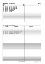
... 506 882-414 LEAFLET NO. CODE NO. USED 1 1 1 1 1 1 REMARKS --- 4 --- * ALTERNATIVE PARTS Printed in Japan 5 -- 03 (030510N) BAR WRENCH 5MM 503 944-458 HEX. DESCRIPTION 601 881-768 GRIP TAPE (A) 602 880-407 TAPE 603 877-153 PNEUMATIC TOOL LUBRICANT (30CC) 604 874-042 PNEUMATIC TOOL LUBRICANT (120CC) 605 876-212 PNEUMATIC TOOL LUBRICANT (1L) 606 317-918...
... 506 882-414 LEAFLET NO. CODE NO. USED 1 1 1 1 1 1 REMARKS --- 4 --- * ALTERNATIVE PARTS Printed in Japan 5 -- 03 (030510N) BAR WRENCH 5MM 503 944-458 HEX. DESCRIPTION 601 881-768 GRIP TAPE (A) 602 880-407 TAPE 603 877-153 PNEUMATIC TOOL LUBRICANT (30CC) 604 874-042 PNEUMATIC TOOL LUBRICANT (120CC) 605 876-212 PNEUMATIC TOOL LUBRICANT (1L) 606 317-918...


