Instruction Manual
Page 4
...from binding and other accessories. 14. Ordinary eyeglasses do not provide adequate protection because the lenses are not made of the slide compound miter saw. 25. ALWAYS DISCONNECT THE TOOL before servicing and before attempting to use only recommended accessories in order to operate the tool.... OBSERVE THE FOLLOWING RULES TO ASSURE SAFE USE OF THIS TOOL: 1. This tool was not designed to the tool. 23. Never raise the saw blade. 17. Specific Safety Rules for proper alignment, freedom from the workpiece until it . 2. Also, use outboard stands to this instruction manual...
...from binding and other accessories. 14. Ordinary eyeglasses do not provide adequate protection because the lenses are not made of the slide compound miter saw. 25. ALWAYS DISCONNECT THE TOOL before servicing and before attempting to use only recommended accessories in order to operate the tool.... OBSERVE THE FOLLOWING RULES TO ASSURE SAFE USE OF THIS TOOL: 1. This tool was not designed to the tool. 23. Never raise the saw blade. 17. Specific Safety Rules for proper alignment, freedom from the workpiece until it . 2. Also, use outboard stands to this instruction manual...
Instruction Manual
Page 5
... bevel cutting, always wait for use outboard stands to provide support for the tool to stop rotating before attempting slide cutting. 18. Always keep your hair is free of the slide compound miter saw at once, if you fully understand the operating instructions contained in the instruction manual. 5. Always wear snug-fitting clothing, non-skid...
... bevel cutting, always wait for use outboard stands to provide support for the tool to stop rotating before attempting slide cutting. 18. Always keep your hair is free of the slide compound miter saw at once, if you fully understand the operating instructions contained in the instruction manual. 5. Always wear snug-fitting clothing, non-skid...
Instruction Manual
Page 6
...Hitachi authorized service center. 6 When slide cutting, never pull the handle toward the operator, since this saw unless all the blade guards are in damp locations. 22. Never use in place. 17. WARNING FOR YOUR OWN SAFETY READ THIS INSTRUCTION MANUAL BEFORE OPERATING THE SLIDE COMPOUND MITER SAW... 1. Never perform any freehand operation with solvents because the plastic may cause hazardous conditions. 20. Always disconnect power before using the slide compound miter saw blade. 6. Saw blade diameter is 5,500/min. ...
...Hitachi authorized service center. 6 When slide cutting, never pull the handle toward the operator, since this saw unless all the blade guards are in damp locations. 22. Never use in place. 17. WARNING FOR YOUR OWN SAFETY READ THIS INSTRUCTION MANUAL BEFORE OPERATING THE SLIDE COMPOUND MITER SAW... 1. Never perform any freehand operation with solvents because the plastic may cause hazardous conditions. 20. Always disconnect power before using the slide compound miter saw blade. 6. Saw blade diameter is 5,500/min. ...
Instruction Manual
Page 8
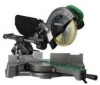
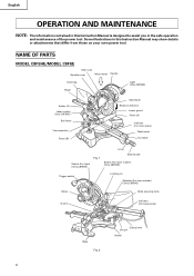
... on your own power tool. NAME OF PARTS MODEL C8FSHE/MODEL C8FSE Gear case Spindle cover Motor head Handle Dust bag Hinge Light (Only C8FSHE)... Holder (A) Laser marker (Only C8FSHE) Sub fence Vise assembly Fence (B) Saw blade Rotation direction Lower guard Fence (A) Indicator (For miter scale) Table insert Turntable Lever Switch (For light) (Only C8FSHE) Fig.... 1 Side handle Switch (For laser marker) (Only C8FSHE) Trigger switch Locking pin Adjuster (For laser marker) (Only C8FSHE) Motor Slide...
... on your own power tool. NAME OF PARTS MODEL C8FSHE/MODEL C8FSE Gear case Spindle cover Motor head Handle Dust bag Hinge Light (Only C8FSHE)... Holder (A) Laser marker (Only C8FSHE) Sub fence Vise assembly Fence (B) Saw blade Rotation direction Lower guard Fence (A) Indicator (For miter scale) Table insert Turntable Lever Switch (For light) (Only C8FSHE) Fig.... 1 Side handle Switch (For laser marker) (Only C8FSHE) Trigger switch Locking pin Adjuster (For laser marker) (Only C8FSHE) Motor Slide...
Instruction Manual
Page 9
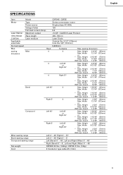
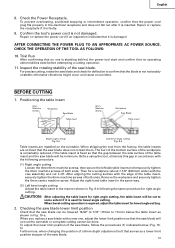
English SPECIFICATIONS Item Model C8FSHE / C8FSE Motor Type Series commutator motor Power source Single-phase AC 60Hz Voltage (Volts) 120 Full-load current (Amp) 9.2 Laser Marker Maximum output
English SPECIFICATIONS Item Model C8FSHE / C8FSE Motor Type Series commutator motor Power source Single-phase AC 60Hz Voltage (Volts) 120 Full-load current (Amp) 9.2 Laser Marker Maximum output
Instruction Manual
Page 10
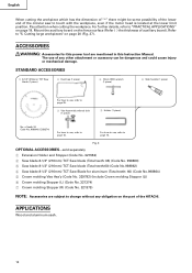
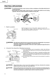
... No. 321553) 2 Saw blade 8-1/2" (216mm) TCT Saw blade (Total teeth: 36) (Code No. 998860) 3 Saw blade 8-1/2" (216mm) TCT Saw blade (Total teeth:60) (Code No.998862) 4 Saw blade 8-1/2" (216mm) TCT Saw Blade for this power tool are subject to "PRACTICAL APPLICATIONS" on the part of the HITACHI. For further details, refer... to change without any other attachment or accessory can be some possibility of the lower end of the circular saw to "5. Mount the auxiliary board on page 20 (Fig. 27)....
... No. 321553) 2 Saw blade 8-1/2" (216mm) TCT Saw blade (Total teeth: 36) (Code No. 998860) 3 Saw blade 8-1/2" (216mm) TCT Saw blade (Total teeth:60) (Code No.998862) 4 Saw blade 8-1/2" (216mm) TCT Saw Blade for this power tool are subject to "PRACTICAL APPLICATIONS" on the part of the HITACHI. For further details, refer... to change without any other attachment or accessory can be some possibility of the lower end of the circular saw to "5. Mount the auxiliary board on page 20 (Fig. 27)....
Instruction Manual
Page 12
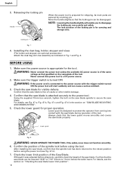
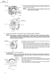
... it was adjusted before using the power tool (see Fig. 47-b). 7. Move the handle slightly so that the lower guard moves smoothly and covers the saw blade lower limit position". 12 Always check that the locking pin can be lowered 13/32" to 7/16" (10mm to the power tool. Lower guard...-a, Fig. 47-b, Fig. 47-c and Fig. 47-d in Fig. 1 and Fig. 2. Make sure the power source is free of the tool. Confirm that specified on "SAW BLADE MOUNTING AND DISMOUNTING". 5. Check the lower guard for the tool. Lower guard is attached securely to 11mm) below the table insert. Check the lower...
... it was adjusted before using the power tool (see Fig. 47-b). 7. Move the handle slightly so that the lower guard moves smoothly and covers the saw blade lower limit position". 12 Always check that the locking pin can be lowered 13/32" to 7/16" (10mm to the power tool. Lower guard...-a, Fig. 47-b, Fig. 47-c and Fig. 47-d in Fig. 1 and Fig. 2. Make sure the power source is free of the tool. Confirm that specified on "SAW BLADE MOUNTING AND DISMOUNTING". 5. Check the lower guard for the tool. Lower guard is attached securely to 11mm) below the table insert. Check the lower...
Instruction Manual
Page 13
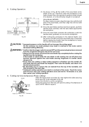
... will be lowered 13/32" to 7/16" (10mm to some extent if it is used for bevel angle cutting. 2. Checking the saw blade lower limit position Check that no operating abnormalities exist before attempting a cutting operation. 11. Inspect the rotating stability of both ends. otherwise...angle cutting Loosen the three 6mm machine screws, then secure the left side table insert and temporarily tighten the 6mm machine screws of the saw blade does not contact them. To prevent overheating, accidental stopping or intermittent operation, confirm that the power cord plug fits properly in ...
... will be lowered 13/32" to 7/16" (10mm to some extent if it is used for bevel angle cutting. 2. Checking the saw blade lower limit position Check that no operating abnormalities exist before attempting a cutting operation. 11. Inspect the rotating stability of both ends. otherwise...angle cutting Loosen the three 6mm machine screws, then secure the left side table insert and temporarily tighten the 6mm machine screws of the saw blade does not contact them. To prevent overheating, accidental stopping or intermittent operation, confirm that the power cord plug fits properly in ...
Instruction Manual
Page 14
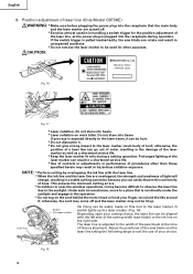
...depth adjustment bolt, change the height where the bolt head and the hinge contacts, and adjust the lower limit Gear case position of the saw blade may contact the sub fence, resulting in an injury. Right bevel This power tool is Equipped with a wide back face. Confirmation...10-a) will not cut into the turntable. Hinge Fig. 10-a Turntable Turn 8mm Depth adjustment bolt Gear case Fig. 10-b 3. Lower limit position of saw blade when cutting a large workpiece NOTE: When cutting a workpiece exceeding 2-9/16" (65mm) in height in right-angle cutting or 1-25/32"(45mm)...
...depth adjustment bolt, change the height where the bolt head and the hinge contacts, and adjust the lower limit Gear case position of the saw blade may contact the sub fence, resulting in an injury. Right bevel This power tool is Equipped with a wide back face. Confirmation...10-a) will not cut into the turntable. Hinge Fig. 10-a Turntable Turn 8mm Depth adjustment bolt Gear case Fig. 10-b 3. Lower limit position of saw blade when cutting a large workpiece NOTE: When cutting a workpiece exceeding 2-9/16" (65mm) in height in right-angle cutting or 1-25/32"(45mm)...
Instruction Manual
Page 16
... your finger, wood and the like around it may result in handling a switch trigger for the position adjustment of lines. Adjust the positions of the saw blade) or the ink line on this tool to be used for other than those specified herein may become difficult to observe the laser line... order, resulting in the damage of the laser marker as well as the power plug is plugged into the receptacle that is pulled inadvertently, the saw blade at the time of light will change, resulting in a stable cutting operation because you can be hurt. * Do not dismantle it can result in...
... your finger, wood and the like around it may result in handling a switch trigger for the position adjustment of lines. Adjust the positions of the saw blade) or the ink line on this tool to be used for other than those specified herein may become difficult to observe the laser line... order, resulting in the damage of the laser marker as well as the power plug is plugged into the receptacle that is pulled inadvertently, the saw blade at the time of light will change, resulting in a stable cutting operation because you can be hurt. * Do not dismantle it can result in...
Instruction Manual
Page 17
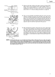
...end of the groove. (Fig. 20) When you align it with the right side of the saw blade, align the laser line with the ink line [The deviation between the ink line and the ... on the grooving again and check the position of the laser line. When aligning the ink line, slide the workpiece little by vise at a position where the laser line overlaps with the laser line. Work...the workpiece that the laser line is in line with the right side of the groove. English Workpiece Saw Blade Marking (pre-marked) Cutting Width Fig. 19 Vise Assembly Move Turn Laser Line Groove Adjuster Fig....
...end of the groove. (Fig. 20) When you align it with the right side of the saw blade, align the laser line with the ink line [The deviation between the ink line and the ... on the grooving again and check the position of the laser line. When aligning the ink line, slide the workpiece little by vise at a position where the laser line overlaps with the laser line. Work...the workpiece that the laser line is in line with the right side of the groove. English Workpiece Saw Blade Marking (pre-marked) Cutting Width Fig. 19 Vise Assembly Move Turn Laser Line Groove Adjuster Fig....
Instruction Manual
Page 18
... (see Fig. 1) does not contact the vise assembly when it may cause hazardous conditions (see Fig. 22). Fig. 23 WARNING: This will not contact the saw blade. 18 This may do so, loosen the 6 mm wing bolt (B) and move the vise assembly to the Vise plate height of the workpiece by...
... (see Fig. 1) does not contact the vise assembly when it may cause hazardous conditions (see Fig. 22). Fig. 23 WARNING: This will not contact the saw blade. 18 This may do so, loosen the 6 mm wing bolt (B) and move the vise assembly to the Vise plate height of the workpiece by...
Instruction Manual
Page 19
... to scatter about dangerously. * Every time one cutting or deep-cutting operation is finished, turn the power tool OFF and let the saw blade has stopped. Therefore, slide the workpiece to the right (viewed from the workpiece. Then raise the handle, and return it to 2-9/16" (65mm) square. ...Hinge Lower the handle to the next step. * Continued cutting operation can result in Fig. 25 the width of the saw blade is desired, or to holder (A), then tighten the slide securing knob (see Fig. 2) as indicated in use. * Always turn the power off , and check that the...
... to scatter about dangerously. * Every time one cutting or deep-cutting operation is finished, turn the power tool OFF and let the saw blade has stopped. Therefore, slide the workpiece to the right (viewed from the workpiece. Then raise the handle, and return it to 2-9/16" (65mm) square. ...Hinge Lower the handle to the next step. * Continued cutting operation can result in Fig. 25 the width of the saw blade is desired, or to holder (A), then tighten the slide securing knob (see Fig. 2) as indicated in use. * Always turn the power off , and check that the...
Instruction Manual
Page 20
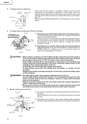
Fig. 27 6. Bevel cutting procedures Holder (A) Set pin Indicator (For bevel scale) (1) Loosen the clamp lever and bevel the saw blade forward. Cutting wide workpieces (Slide cutting) 1 Pull Forward 3 Push Rearward to Cut Handle (1) Workpieces up to 2-15/16" (75mm) high and 10-5/16" (262mm) wide: ... cutting marks on the height of up to 2-9/16" (65mm) high and 12-1/4" (312mm) wide: Loosen the slide securing knob (see Fig. 2), grip the handle and slide the saw blade to the left or to the right. Fig. 28 Workpiece (2) Workpieces up to the desired setting while watching...
Fig. 27 6. Bevel cutting procedures Holder (A) Set pin Indicator (For bevel scale) (1) Loosen the clamp lever and bevel the saw blade forward. Cutting wide workpieces (Slide cutting) 1 Pull Forward 3 Push Rearward to Cut Handle (1) Workpieces up to 2-15/16" (75mm) high and 10-5/16" (262mm) wide: ... cutting marks on the height of up to 2-9/16" (65mm) high and 12-1/4" (312mm) wide: Loosen the slide securing knob (see Fig. 2), grip the handle and slide the saw blade to the left or to the right. Fig. 28 Workpiece (2) Workpieces up to the desired setting while watching...
Instruction Manual
Page 21
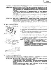
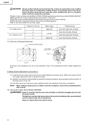
...32 9. Checking the saw blade. Miter cutting procedures Indicator (For miter scale) Side Handle Turntable Turn the Miter Scale turntable Tighten Lever Loosen Pull up Fig. 30 Angle Scale a Grade Scale Miter Scale Fig. 31 (1) Loosen the side handle and pull up the lever for compound cutting, refer to ... hand and cut -off portion will be used for bevel cutting, refer to the initial position. In case of compound cutting (angle + bevel) by sliding the round portion of 2/10, set the indicator to scatter about dangerously. For maximum dimensions for angle stoppers. CAUTION...
...32 9. Checking the saw blade. Miter cutting procedures Indicator (For miter scale) Side Handle Turntable Turn the Miter Scale turntable Tighten Lever Loosen Pull up Fig. 30 Angle Scale a Grade Scale Miter Scale Fig. 31 (1) Loosen the side handle and pull up the lever for compound cutting, refer to ... hand and cut -off portion will be used for bevel cutting, refer to the initial position. In case of compound cutting (angle + bevel) by sliding the round portion of 2/10, set the indicator to scatter about dangerously. For maximum dimensions for angle stoppers. CAUTION...
Instruction Manual
Page 23
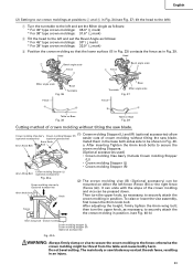
... Fence (2) The crown molding vise (B) (Optional accessory) can be mounted on Base Fig. 39 Cutting method of crown molding without tilting the saw blade. (1) Crown molding Stopper (L) and (R) (optional accessories) allow Crown molding Vise Ass'y Crown molding Stopper (R) (optional accessories) (optional ... side to the fence; The main body or saw blade. 6mm Knob Install them in position. Head Head 1 Bevel angle scale Fence 4 2 Fence Bevel angle scale 3 Miter angle scale Base Turntable Fig. 36 Fence A B Base Turntable Miter angle scale Fig. 37 Fence B A Table ...
... Fence (2) The crown molding vise (B) (Optional accessory) can be mounted on Base Fig. 39 Cutting method of crown molding without tilting the saw blade. (1) Crown molding Stopper (L) and (R) (optional accessories) allow Crown molding Vise Ass'y Crown molding Stopper (R) (optional accessories) (optional ... side to the fence; The main body or saw blade. 6mm Knob Install them in position. Head Head 1 Bevel angle scale Fence 4 2 Fence Bevel angle scale 3 Miter angle scale Base Turntable Fig. 36 Fence A B Base Turntable Miter angle scale Fig. 37 Fence B A Table ...
Instruction Manual
Page 24
...40-b. Tighten the 6mm wing bolt to the lower table for cutting. For inside corner For outside corner Position in Fig. 34 1 2 3 4 Miter angle Right 45° Left 45° Right 45° Finished piece Save the right side of blade Save the left side of blade Save... English CAUTION: Always confirm that the motor head (see b in Fig. 41 by adjusting the 6mm depth adjustment bolt. Position crown molding with saw blade. Refer to secure the crown molding Stoppers. The light lens reaches high temperatures during and immediately after the adjustment has been completed. NOTE: ...
...40-b. Tighten the 6mm wing bolt to the lower table for cutting. For inside corner For outside corner Position in Fig. 34 1 2 3 4 Miter angle Right 45° Left 45° Right 45° Finished piece Save the right side of blade Save the left side of blade Save... English CAUTION: Always confirm that the motor head (see b in Fig. 41 by adjusting the 6mm depth adjustment bolt. Position crown molding with saw blade. Refer to secure the crown molding Stoppers. The light lens reaches high temperatures during and immediately after the adjustment has been completed. NOTE: ...
Instruction Manual
Page 25
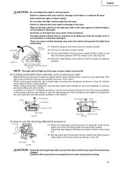
...observe this may result in the market. Make sure that the light is not scratched or otherwise damaged. When cutting aluminum materials, coat the saw blade rotates. Check the dust bag periodically and empty it before it off . 13. Sawdust will cause inefficient cutting and possible overload of the... tighten it using both the vise assembly and the clamp available in damage to the light or a reduced life span. Duct (2) During bevel and compound cutting, attach the dust bag at a right angle to achieve smooth cutting and a fine finish. Only switch the light on the light lens may...
...observe this may result in the market. Make sure that the light is not scratched or otherwise damaged. When cutting aluminum materials, coat the saw blade rotates. Check the dust bag periodically and empty it before it off . 13. Sawdust will cause inefficient cutting and possible overload of the... tighten it using both the vise assembly and the clamp available in damage to the light or a reduced life span. Duct (2) During bevel and compound cutting, attach the dust bag at a right angle to achieve smooth cutting and a fine finish. Only switch the light on the light lens may...
Instruction Manual
Page 26
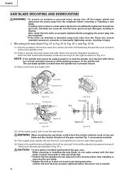
... 6mm bolt fastening the spindle cover and then remove the spindle cover. (2) Press in spindle lock and loosen bolt with the dust guide. English SAW BLADE MOUNTING AND DISMOUNTING WARNING: * To prevent an accident or personal injury, always turn the bolt with 10mm box wrench (standard accessory) while ...applying pressure on the saw blade and the rotation direction of the gear case(see Fig. 1) are attached or detached using tools other than the 10mm box wrench (standard...
... 6mm bolt fastening the spindle cover and then remove the spindle cover. (2) Press in spindle lock and loosen bolt with the dust guide. English SAW BLADE MOUNTING AND DISMOUNTING WARNING: * To prevent an accident or personal injury, always turn the bolt with 10mm box wrench (standard accessory) while ...applying pressure on the saw blade and the rotation direction of the gear case(see Fig. 1) are attached or detached using tools other than the 10mm box wrench (standard...
Instruction Manual
Page 27
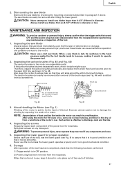
... replace them when they will slide smoothly within the brush holders. Wear Limit Line Brush cap 21 3/16" (5mm) 15/32" (12mm) No. 21 indicates the last two numbers of this tool. 1. WARNING: To prevent personal injury, never operate the power tool if any loose part. The saw blades that they have...
... replace them when they will slide smoothly within the brush holders. Wear Limit Line Brush cap 21 3/16" (5mm) 15/32" (12mm) No. 21 indicates the last two numbers of this tool. 1. WARNING: To prevent personal injury, never operate the power tool if any loose part. The saw blades that they have...


