
Instruction Manual
Page 5
English 12. ALWAYS DISCONNECT THE TOOL before servicing and before changing blades or other damaged components before using the tool. 18. To avoid personal injuries, use only recommended accessories in conjunction with the saw blade from binding and other components for mass-production applications and...volts AC only to the tool. 23. Specific Safety Rules for descriptions of the slide compound miter saw. 25. Always keep tools sharp and clean for changing accessories. 13. Never raise the saw blade. 17. Always follow instructions for lubricating the tool and for the best and ...
English 12. ALWAYS DISCONNECT THE TOOL before servicing and before changing blades or other damaged components before using the tool. 18. To avoid personal injuries, use only recommended accessories in conjunction with the saw blade from binding and other components for mass-production applications and...volts AC only to the tool. 23. Specific Safety Rules for descriptions of the slide compound miter saw. 25. Always keep tools sharp and clean for changing accessories. 13. Never raise the saw blade. 17. Always follow instructions for lubricating the tool and for the best and ...
Instruction Manual
Page 7
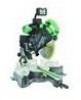
... FOR YOUR OWN SAFETY READ THIS INSTRUCTION MANUAL BEFORE OPERATING THE SLIDE COMPOUND MITER SAW 1. Always keep hands out of the path of the tool. 11. Never reach around the saw blade from the operator in the moving workpiece or changing settings. 7 Never operate the POWER TOOL when you have taken...first come to protect against getting caught in a single, smooth motion. 19. Never damage the power cord of the saw . 5. Never use the POWER TOOL if the starting switch. 12. Never touch any safety devices or blade guards; Never use . 8. Never cut ferrous metals or masonry.
... FOR YOUR OWN SAFETY READ THIS INSTRUCTION MANUAL BEFORE OPERATING THE SLIDE COMPOUND MITER SAW 1. Always keep hands out of the path of the tool. 11. Never reach around the saw blade from the operator in the moving workpiece or changing settings. 7 Never operate the POWER TOOL when you have taken...first come to protect against getting caught in a single, smooth motion. 19. Never damage the power cord of the saw . 5. Never use the POWER TOOL if the starting switch. 12. Never touch any safety devices or blade guards; Never use . 8. Never cut ferrous metals or masonry.
Instruction Manual
Page 8
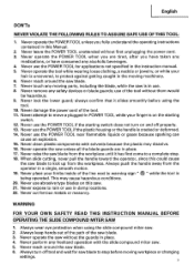
...12 16 16 14 12 14 12 Not Recommended & WARNING: Avoid electrical shock hazard. REPLACEMENT PARTS When servicing use the next heavier gage. When using an extension cord, be conducted only by a Hitachi authorized service center. If in loss of power and overheating. Always disconnect power before changing blade...electrical cords regularly. Never use one heavy enough to use this tool with a damaged or frayed electrical cord or extension cord. Saw blade diameter is possible. 8 USE PROPER EXTENSION CORD Make sure your product will cause a drop in line voltage resulting in doubt,...
...12 16 16 14 12 14 12 Not Recommended & WARNING: Avoid electrical shock hazard. REPLACEMENT PARTS When servicing use the next heavier gage. When using an extension cord, be conducted only by a Hitachi authorized service center. If in loss of power and overheating. Always disconnect power before changing blade...electrical cords regularly. Never use one heavy enough to use this tool with a damaged or frayed electrical cord or extension cord. Saw blade diameter is possible. 8 USE PROPER EXTENSION CORD Make sure your product will cause a drop in line voltage resulting in doubt,...
Instruction Manual
Page 13
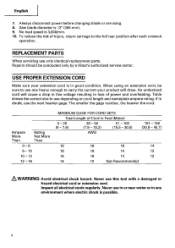
Refer to page 14. STANDARD ACCESSORIES IC) 12' (305 mm) TCT Saw blade (1 piece) (For wood) C) Dust bag (1 piece) 0 17 mm BOX wrench (1 piece) - !/ 1-1... 321373) NOTE: Accessories are mentioned in this Instruction Manual. Cutting large workpieces" on the part of the HITACHI. 13 of teeth 60 Code No. 726100) For how to use , refer to touch with the workpiece... & WARNING: Accessories for this power tool are subject to change without any other attachment or accessory can be some possibility of the lower end of the circular saw to page 38. (I) Vise Assembly w/knob bolt (1 piece...
Refer to page 14. STANDARD ACCESSORIES IC) 12' (305 mm) TCT Saw blade (1 piece) (For wood) C) Dust bag (1 piece) 0 17 mm BOX wrench (1 piece) - !/ 1-1... 321373) NOTE: Accessories are mentioned in this Instruction Manual. Cutting large workpieces" on the part of the HITACHI. 13 of teeth 60 Code No. 726100) For how to use , refer to touch with the workpiece... & WARNING: Accessories for this power tool are subject to change without any other attachment or accessory can be some possibility of the lower end of the circular saw to page 38. (I) Vise Assembly w/knob bolt (1 piece...
Instruction Manual
Page 17
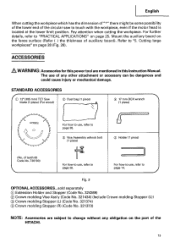
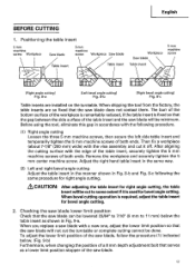
...5mm machine screw Workpiece Saw blade 5mm machine screw Workpiece Saw blade Table insert Table insert Workpiece Saw blade Table insert 5mm machine screw [Right angle cutting] Fig. 8-a [Left bevel angle cuff ng] Fig. 8-b [Right bevel angle cutting] Fig. 8-c Table inserts are so fixed that the saw blade will not cut ... in accordance with a new one, adjust the lower limit position so that the saw blade. 17 After aligning the cutting surface with the vise assembly and cut to 11 mm) below . (Fig. 9-b) Furthermore, when changing the position of a 8 mm depth adjustment bolt that the...
...5mm machine screw Workpiece Saw blade 5mm machine screw Workpiece Saw blade Table insert Table insert Workpiece Saw blade Table insert 5mm machine screw [Right angle cutting] Fig. 8-a [Left bevel angle cuff ng] Fig. 8-b [Right bevel angle cutting] Fig. 8-c Table inserts are so fixed that the saw blade will not cut ... in accordance with a new one, adjust the lower limit position so that the saw blade. 17 After aligning the cutting surface with the vise assembly and cut to 11 mm) below . (Fig. 9-b) Furthermore, when changing the position of a 8 mm depth adjustment bolt that the...
Instruction Manual
Page 18
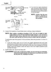
... adjustment bolt C.1 0 Gear case Saw blade (1) Turn the 8 mm depth adjustment bolt, change the height where the bolt head and the hinge contacts, and adjust the lower limit position of the saw blade. -\\ Turntable Fig. 9-a Turn NOTE: Confirm that the saw blade is turned clockwise,the main body or saw blade may contact the sub fence (A), ... cutting or 1-3/4" (45 mm) in contact with the workpiece. Unless it is adjusted so that it will not come in right bevel angle cutting, adjust the lower limit position so that there can be a clearance of 5/64" to 1/8" (2 mm to 3 mm) between the...
... adjustment bolt C.1 0 Gear case Saw blade (1) Turn the 8 mm depth adjustment bolt, change the height where the bolt head and the hinge contacts, and adjust the lower limit position of the saw blade. -\\ Turntable Fig. 9-a Turn NOTE: Confirm that the saw blade is turned clockwise,the main body or saw blade may contact the sub fence (A), ... cutting or 1-3/4" (45 mm) in contact with the workpiece. Unless it is adjusted so that it will not come in right bevel angle cutting, adjust the lower limit position so that there can be a clearance of 5/64" to 1/8" (2 mm to 3 mm) between the...
Instruction Manual
Page 19
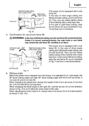
...Then, you can realize stable cutting of right bevel cutting, raise the sub fence (A) up as shown in Fig. 12-b and incline the motor head to its initial position as illustrated in Fig.11 and turn it is turned counterclockwise, the main body or saw blade may contact the sub fence (B), resulting in ... right. When adjusting the motor head to the right 45°, pull the set screw, 8 mm bolt (A), or 8 mm bolt (B) by turning them. When changing the bevel angle to 0°, always return the set screw, 8 mm bolt (A) and 8 mm bolt (B). In the case of sub fence (B) &WARNING: In the case...
...Then, you can realize stable cutting of right bevel cutting, raise the sub fence (A) up as shown in Fig. 12-b and incline the motor head to its initial position as illustrated in Fig.11 and turn it is turned counterclockwise, the main body or saw blade may contact the sub fence (B), resulting in ... right. When adjusting the motor head to the right 45°, pull the set screw, 8 mm bolt (A), or 8 mm bolt (B) by turning them. When changing the bevel angle to 0°, always return the set screw, 8 mm bolt (A) and 8 mm bolt (B). In the case of sub fence (B) &WARNING: In the case...
Instruction Manual
Page 21
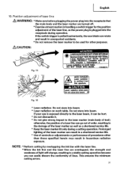
... of a laser line can go out of order,resulting in the damage of the laser marker as well as the power plug is pulledinadvertently,the saw blade can result in a shortened service life. * Use of controls or adjustments or performance of laser line ,A WARNING: * Make sure before plugging the power plug... into the receptacle that the main body and the laser marker are overlapped, the strength and weakness of light will change,resulting in unexpected accidents. * Do not remove the laser marker to be hurt. * Do not dismantle it. * Do not give strong impact to ...
... of a laser line can go out of order,resulting in the damage of the laser marker as well as the power plug is pulledinadvertently,the saw blade can result in a shortened service life. * Use of controls or adjustments or performance of laser line ,A WARNING: * Make sure before plugging the power plug... into the receptacle that the main body and the laser marker are overlapped, the strength and weakness of light will change,resulting in unexpected accidents. * Do not remove the laser marker to be hurt. * Do not dismantle it. * Do not give strong impact to ...
Instruction Manual
Page 29
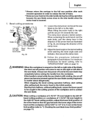
... direction of the arrow mark as illustrated in Fig. 30, and change the direction of the blade, the short cut -off portion will be caught in the cutting groove of the workpiece and to contact the saw blade comes close to the side handle when the motor head is secured ...workpiece of 2-15/16" (75 mm) height in the left side of the saw blade is raised while the saw blade. Bevel cutting procedures Clamp Lever M 0 Holder (A) Pull 4r-lZ Indicator Bevel Set pin (A) (for bevel cutting, refer to rest on page 12. If the handle is still rotating, the cut -off piece may become jammed ...
... direction of the arrow mark as illustrated in Fig. 30, and change the direction of the blade, the short cut -off portion will be caught in the cutting groove of the workpiece and to contact the saw blade comes close to the side handle when the motor head is secured ...workpiece of 2-15/16" (75 mm) height in the left side of the saw blade is raised while the saw blade. Bevel cutting procedures Clamp Lever M 0 Holder (A) Pull 4r-lZ Indicator Bevel Set pin (A) (for bevel cutting, refer to rest on page 12. If the handle is still rotating, the cut -off piece may become jammed ...


