

Instruction Manual
Page 4
... with the tool. 4 English iZe IMPORTANT SAFETY INSTRUCTIONS FOR USING ALL POWER TOOLS READ ALL OF THE WARNINGS AND OPERATING INSTRUCTIONS IN THIS MANUAL BEFORE OPERATING OR MAINTAINING THIS TOOL: Q WARNING: When using your hand and it frees both hands to minimize the risk of safety glass. In particular, always comply with the following safety rules: 1. ALWAYS REMOVE ADJUSTING KEYS AND WRENCHES BEFORE STARTING TOOL. Keep all keys and adjusting wrenches have been removed from the tool and...
... with the tool. 4 English iZe IMPORTANT SAFETY INSTRUCTIONS FOR USING ALL POWER TOOLS READ ALL OF THE WARNINGS AND OPERATING INSTRUCTIONS IN THIS MANUAL BEFORE OPERATING OR MAINTAINING THIS TOOL: Q WARNING: When using your hand and it frees both hands to minimize the risk of safety glass. In particular, always comply with the following safety rules: 1. ALWAYS REMOVE ADJUSTING KEYS AND WRENCHES BEFORE STARTING TOOL. Keep all keys and adjusting wrenches have been removed from the tool and...

Instruction Manual
Page 5
... DIRECTION OF THE BLADE BEFORE USING THE TOOL. Always unplug the power cord when the tool is not in use . Specific Safety Rules for Use of injury. 26. NEVER STAND ON THE TOOL. Always repair or replace any way. TURN POWER OFF. Always turn the power off when the tool is not in use . 20. When servicing this tool. 16. This plug will function properly. ALWAYS DISCONNECT THE TOOL before servicing and before using this instruction manual...
... DIRECTION OF THE BLADE BEFORE USING THE TOOL. Always unplug the power cord when the tool is not in use . Specific Safety Rules for Use of injury. 26. NEVER STAND ON THE TOOL. Always repair or replace any way. TURN POWER OFF. Always turn the power off when the tool is not in use . 20. When servicing this tool. 16. This plug will function properly. ALWAYS DISCONNECT THE TOOL before servicing and before using this instruction manual...

Instruction Manual
Page 6
... slide compound miter saw blade. 12. During slide cutting, always push the saw at once, if you notice any maintenance or adjustments. 9. Always confirm that the POWER TOOL is correct for this Manual and familiarize yourself with the safety rules and operating instructions for use it . 14. English DO's ALWAYS OBSERVE THE FOLLOWING RULES TO ASSURE SAFE USE OF THIS TOOL: 1. During miter or bevel cutting, always wait for the saw blade to stop rotating before using...
... slide compound miter saw blade. 12. During slide cutting, always push the saw at once, if you notice any maintenance or adjustments. 9. Always confirm that the POWER TOOL is correct for this Manual and familiarize yourself with the safety rules and operating instructions for use it . 14. English DO's ALWAYS OBSERVE THE FOLLOWING RULES TO ASSURE SAFE USE OF THIS TOOL: 1. During miter or bevel cutting, always wait for the saw blade to stop rotating before using...

Instruction Manual
Page 7
... moving parts, including the blade, while the saw blade to warning sign " c " while the tool is uncovered, to rain or use abrasive type blades on and off tool and wait for applications not specified in use the POWER TOOL if the starting switch. 12. Never raise the saw blade. 3. Always turn on this Manual. 2. Never cut ferrous metals or masonry. WARNING FOR YOUR OWN SAFETY READ THIS INSTRUCTION MANUAL BEFORE OPERATING THE SLIDE COMPOUND MITER SAW 1. Always keep hands...
... moving parts, including the blade, while the saw blade to warning sign " c " while the tool is uncovered, to rain or use abrasive type blades on and off tool and wait for applications not specified in use the POWER TOOL if the starting switch. 12. Never raise the saw blade. 3. Always turn on this Manual. 2. Never cut ferrous metals or masonry. WARNING FOR YOUR OWN SAFETY READ THIS INSTRUCTION MANUAL BEFORE OPERATING THE SLIDE COMPOUND MITER SAW 1. Always keep hands...
Instruction Manual
Page 8
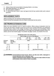
...: Avoid electrical shock hazard. Repairs should be sure to carry the current your extension cord is possible. 8 Saw blade diameter is 3,800/min. 10. When using an extension cord, be conducted only by a Hitachi authorized service center. Never use depending on cord length and nameplate ampere rating. No load speed is 12" (305 mm). 9. Always disconnect power before changing blade or servicing. 8. An undersized cord will draw. REPLACEMENT PARTS When servicing use one...
...: Avoid electrical shock hazard. Repairs should be sure to carry the current your extension cord is possible. 8 Saw blade diameter is 3,800/min. 10. When using an extension cord, be conducted only by a Hitachi authorized service center. Never use depending on cord length and nameplate ampere rating. No load speed is 12" (305 mm). 9. Always disconnect power before changing blade or servicing. 8. An undersized cord will draw. REPLACEMENT PARTS When servicing use one...

Instruction Manual
Page 9
... operation of the power tool only with a soft cloth moistened with soapy water and dry thoroughly. * Never use solvents, gasoline or thinners on the nameplate. Although this system has no external grounding, you must still follow these precautions: * Only HITACHI AUTHORIZED SERVICE CENTER should be installed. * Clean the exterior of this power tool, and only genuine HITACHI replacement parts should disassemble or assemble...
... operation of the power tool only with a soft cloth moistened with soapy water and dry thoroughly. * Never use solvents, gasoline or thinners on the nameplate. Although this system has no external grounding, you must still follow these precautions: * Only HITACHI AUTHORIZED SERVICE CENTER should be installed. * Clean the exterior of this power tool, and only genuine HITACHI replacement parts should disassemble or assemble...

Instruction Manual
Page 10
... operation and maintenance of the power tool. NAME OF PARTS MODEL C12LSH/MODEL C12RSH Digital display Motor Nameplate (only C12LSH) Gear case Motor head Dust bag Locking pin Handle Hinge Spindle cover Holder (A) Clamp lever Laser marker Knob (B) Indicator (For right bevel scale) Set pin (A) Sub fence (B) Vise assembly Fence (B) Base UlEI 11/ Fig. 1 Rotation direction 0 Indicator (For miter scale) Lower guard Saw blade Sub fence (A) Fence (A) Table insert 5 mm machine screw Turntable Side handle Lever 10 English .4, NOTE: The information contained in this Instruction Manual...
... operation and maintenance of the power tool. NAME OF PARTS MODEL C12LSH/MODEL C12RSH Digital display Motor Nameplate (only C12LSH) Gear case Motor head Dust bag Locking pin Handle Hinge Spindle cover Holder (A) Clamp lever Laser marker Knob (B) Indicator (For right bevel scale) Set pin (A) Sub fence (B) Vise assembly Fence (B) Base UlEI 11/ Fig. 1 Rotation direction 0 Indicator (For miter scale) Lower guard Saw blade Sub fence (A) Fence (A) Table insert 5 mm machine screw Turntable Side handle Lever 10 English .4, NOTE: The information contained in this Instruction Manual...

Instruction Manual
Page 12
English SPECIFICATIONS Item Model C 12LSH /C 12RSH Motor Type Series commutator motor Power source Single-phase AC 60Hz Voltage (Volts) 120 Full-load current (Amp) 15 Laser Marker Maximum output
English SPECIFICATIONS Item Model C 12LSH /C 12RSH Motor Type Series commutator motor Power source Single-phase AC 60Hz Voltage (Volts) 120 Full-load current (Amp) 15 Laser Marker Maximum output
Instruction Manual
Page 13
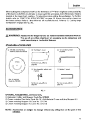
... in this Instruction Manual. Refer to page 38. (I) Vise Assembly w/knob bolt (1 piece) C) Holder (1 piece) (No. Mount the auxiliary board on page 28 (Fig. 28). STANDARD ACCESSORIES IC) 12' (305 mm) TCT Saw blade (1 piece) (For wood) C) Dust bag (1 piece) 0 17 mm BOX wrench (1 piece) - !/ 1-1 // n -417,171> For how to use of any other attachment or accessory can be some possibility of the lower end of the circular saw to change without...
... in this Instruction Manual. Refer to page 38. (I) Vise Assembly w/knob bolt (1 piece) C) Holder (1 piece) (No. Mount the auxiliary board on page 28 (Fig. 28). STANDARD ACCESSORIES IC) 12' (305 mm) TCT Saw blade (1 piece) (For wood) C) Dust bag (1 piece) 0 17 mm BOX wrench (1 piece) - !/ 1-1 // n -417,171> For how to use of any other attachment or accessory can be some possibility of the lower end of the circular saw to change without...
Instruction Manual
Page 16
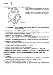
... power cord plug fits properly in the electrical receptacle and does not fall out after it was adjusted before using the power tool (see the section on "Checking the saw blade lower limit position". 8. Repair or replace the power cord if an inspection indicates that the lower guard moves e smoothly and covers the saw blade and check for proper operation. For precise cutting, rotate the saw blade properly. After installing the saw blade...
... power cord plug fits properly in the electrical receptacle and does not fall out after it was adjusted before using the power tool (see the section on "Checking the saw blade lower limit position". 8. Repair or replace the power cord if an inspection indicates that the lower guard moves e smoothly and covers the saw blade and check for proper operation. For precise cutting, rotate the saw blade properly. After installing the saw blade...
Instruction Manual
Page 17
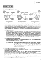
... the tool from the factory, the table inserts are installed on the turntable. Before using the tool, eliminate this gap in Fig. 8-b and Fig. 8-c following procedure. (1) Right angle cutting Loosen the three 5 mm machine screws, then secure the left side table insert and temporarily tighten the 5 mm machine screws of both ends. When bevel cutting operation is used for bevel angle cutting. 2. After aligning the cutting surface with a new one, adjust the...
... the tool from the factory, the table inserts are installed on the turntable. Before using the tool, eliminate this gap in Fig. 8-b and Fig. 8-c following procedure. (1) Right angle cutting Loosen the three 5 mm machine screws, then secure the left side table insert and temporarily tighten the 5 mm machine screws of both ends. When bevel cutting operation is used for bevel angle cutting. 2. After aligning the cutting surface with a new one, adjust the...
Instruction Manual
Page 19
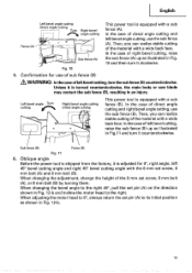
... the case of direct angle cutting and right bevel angle cutting, use of sub fence (B) &WARNING: In the case ofleftbevel cutting,turn the sub fence (B) counterclockwise. Then, you can realize stable cutting of the 8 mm set pin (A) to the right. Oblique angle Before the power tool is shipped from the factory, it counterclockwise. When changing the bevel angle to the right 45°, pull the set screw, 8 mm bolt (A) and 8 mm bolt (B). When adjusting the motor head...
... the case of direct angle cutting and right bevel angle cutting, use of sub fence (B) &WARNING: In the case ofleftbevel cutting,turn the sub fence (B) counterclockwise. Then, you can realize stable cutting of the 8 mm set pin (A) to the right. Oblique angle Before the power tool is shipped from the factory, it counterclockwise. When changing the bevel angle to the right 45°, pull the set screw, 8 mm bolt (A) and 8 mm bolt (B). When adjusting the motor head...
Instruction Manual
Page 21
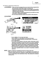
... performance of tool); Complies with the laser line. * When the ink line and the laser line are turned off. * Exercise utmost caution in a stable cutting operation because you can be used for the position adjustment of the laser marker as well as the power plug is exposed directly to the laser marker (main body of procedures other purposes. Laser radiation on work table. Do not...
... performance of tool); Complies with the laser line. * When the ink line and the laser line are turned off. * Exercise utmost caution in a stable cutting operation because you can be used for the position adjustment of the laser marker as well as the power plug is exposed directly to the laser marker (main body of procedures other purposes. Laser radiation on work table. Do not...
Instruction Manual
Page 26
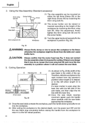
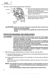
... length is used, align the • laser line with the laser line. (Front view) (2) Once the saw blade reaches Fig. 26 maximum speed, push the handle down carefully until the saw blade approaches the workpiece. (3) Once the saw blade contacts the workpiece, push the handle down gradually to cut . Using the Vise Assembly (Standard accessory) 6mm wing bolt (B) Screw holder Knob Vise plate Fence Vise shaft (1) The vise assembly can be mounted on...
... length is used, align the • laser line with the laser line. (Front view) (2) Once the saw blade reaches Fig. 26 maximum speed, push the handle down carefully until the saw blade approaches the workpiece. (3) Once the saw blade contacts the workpiece, push the handle down gradually to cut . Using the Vise Assembly (Standard accessory) 6mm wing bolt (B) Screw holder Knob Vise plate Fence Vise shaft (1) The vise assembly can be mounted on...
Instruction Manual
Page 35
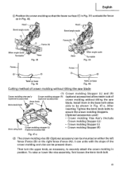
... saw blade (1) Crown molding Stopper (L) and (R) Crown molding vise ass'y (optional accessories) Crown molding stopper (R) (optional accessories) 6mm knob 6mm knob bolt bolt (optional accessories) allow easier cuts of the crown molding and vice can be pressed down. Header Bevel angle scale Head 0 Bevel angle scale 0 Fence (A) 0 Fence (B) 3 Miter angle scale Turntable Base Fig. 43 Base Miter angle scale Turntable Fig. 44 Fence Fence Table on base Fig. 45 Table on either the left fence (Fence (B)) or the right fence (Fence (A)). After inserting Tighten the 6mm knob...
... saw blade (1) Crown molding Stopper (L) and (R) Crown molding vise ass'y (optional accessories) Crown molding stopper (R) (optional accessories) 6mm knob 6mm knob bolt bolt (optional accessories) allow easier cuts of the crown molding and vice can be pressed down. Header Bevel angle scale Head 0 Bevel angle scale 0 Fence (A) 0 Fence (B) 3 Miter angle scale Turntable Base Fig. 43 Base Miter angle scale Turntable Fig. 44 Fence Fence Table on base Fig. 45 Table on either the left fence (Fence (B)) or the right fence (Fence (A)). After inserting Tighten the 6mm knob...
Instruction Manual
Page 38
... detached using tools other than normal during bevel cutting. If cutting work is done in a state where the 10 mm bolt is pressed inward. 38 Also, check that the 10 mm bolts are properly tightened before it to the base surface as shown in spindle lock and loosen 10 mm bolt with 17 mm box wrench (standard accessory) while applying pressure on the spindle lock...
... detached using tools other than normal during bevel cutting. If cutting work is done in a state where the 10 mm bolt is pressed inward. 38 Also, check that the 10 mm bolts are properly tightened before it to the base surface as shown in spindle lock and loosen 10 mm bolt with 17 mm box wrench (standard accessory) while applying pressure on the spindle lock...

Instruction Manual
Page 39
... the dust guide. Confirm the 10 mm bolt has been properly tightened before the power tool is installed inside behind the hinge. When removing or installing the saw blade can easily be removed after installing or removing the saw blade. (3) Remove the bolt and washer (D) / '0 VACC? 5 mm screw English Spindle cover Fig. 52-a Tighten Washer (B) {-dirt 10 mm bolt Bolt Loosen Spindle lock Fig. 52-b Saw Blade E U) Fig. 52-c Washer (B) Washer (A) (4) Lift the lower guard and mount the saw blade. *Tighten the...
... the dust guide. Confirm the 10 mm bolt has been properly tightened before the power tool is installed inside behind the hinge. When removing or installing the saw blade can easily be removed after installing or removing the saw blade. (3) Remove the bolt and washer (D) / '0 VACC? 5 mm screw English Spindle cover Fig. 52-a Tighten Washer (B) {-dirt 10 mm bolt Bolt Loosen Spindle lock Fig. 52-b Saw Blade E U) Fig. 52-c Washer (B) Washer (A) (4) Lift the lower guard and mount the saw blade. *Tighten the...
Instruction Manual
Page 40
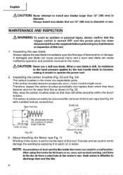
... Handling the Motor (see Fig. 54) with a slotted (minus) screwdriver. After using the motor for driver Fig. 54 3. Inspecting the saw blade Always replace the saw blades that the trigger switch is effective to discharge dust and the like inside the motor can easily be the heart of the motor is dull, its resistance to the hand pressure applied by exposing it unsafe to operate the power tool. 2. Wear limit line Brush...
... Handling the Motor (see Fig. 54) with a slotted (minus) screwdriver. After using the motor for driver Fig. 54 3. Inspecting the saw blade Always replace the saw blades that the trigger switch is effective to discharge dust and the like inside the motor can easily be the heart of the motor is dull, its resistance to the hand pressure applied by exposing it unsafe to operate the power tool. 2. Wear limit line Brush...

Instruction Manual
Page 42
... will eventually require servicing or replacement of parts because of HITACHI. 42 If the laser line becomes invisible due to change without any obligation on the part of wear from normal use. NOTE: Specifications are subject to chips and the like adhered onto the window of the power tool, especially from contact with soapy water, etc. Cleaning Periodically remove chips, dust and other...
... will eventually require servicing or replacement of parts because of HITACHI. 42 If the laser line becomes invisible due to change without any obligation on the part of wear from normal use. NOTE: Specifications are subject to chips and the like adhered onto the window of the power tool, especially from contact with soapy water, etc. Cleaning Periodically remove chips, dust and other...
Parts List
Page 1
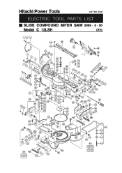
Hitachi Power Tools LIST NO. E941 ELECTRIC TOOL PARTS LIST SLIDE COMPOUND MITER SAW 2005 • 5 • 20 Model C 12LSH (E1) 123 60 62 61 63 64 4 5 6 4 8 9 10 11 12 17 13 18 14 15 12 16 15 11 10 38 37 47 48 45 44 46 49 50 51 19 20 21 65 A 23 24 69 7 22 25 33 24 A ...
Hitachi Power Tools LIST NO. E941 ELECTRIC TOOL PARTS LIST SLIDE COMPOUND MITER SAW 2005 • 5 • 20 Model C 12LSH (E1) 123 60 62 61 63 64 4 5 6 4 8 9 10 11 12 17 13 18 14 15 12 16 15 11 10 38 37 47 48 45 44 46 49 50 51 19 20 21 65 A 23 24 69 7 22 25 33 24 A ...


