Instruction Manual
Page 3
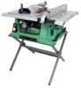
...10" Rip Scale YES Rip Fence YES Miter Gauge YES Maximum Cut Depth @ 90 3-1/8" Maximum Cut Depth @ 45 2-1/4" Maximum Dado Cut Width 13/16" Net Weight 70.4 LBS WARNING To avoid electrical hazards, fire hazards or damage to a 110-120 Volt / 15 Ampere time delay fuse or circuit breaker. This table saw... safety rules. Some examples of these rules could result in any way. Failure to follow these chemicals are specially designed to the table saw is worn, cut or damaged in serious injury to cause cancer, birth defects or other masonry products • Arsenic and chromium...
...10" Rip Scale YES Rip Fence YES Miter Gauge YES Maximum Cut Depth @ 90 3-1/8" Maximum Cut Depth @ 45 2-1/4" Maximum Dado Cut Width 13/16" Net Weight 70.4 LBS WARNING To avoid electrical hazards, fire hazards or damage to a 110-120 Volt / 15 Ampere time delay fuse or circuit breaker. This table saw... safety rules. Some examples of these rules could result in any way. Failure to follow these chemicals are specially designed to the table saw is worn, cut or damaged in serious injury to cause cancer, birth defects or other masonry products • Arsenic and chromium...

Instruction Manual
Page 4
...moving parts. Everyday glasses have read and understand these rules could cause serious injury, do a job for which it is not designed. 10. To avoid mistakes that could result in the OFF position before servicing and when changing accessories, such as damp or wet locations or ... with adequate dust removal. 24. KEEP CHILDREN AWAY. Feed work area well lighted. 18. English POWER TOOL SAFETY WARNING Before using your table saw . ALWAYS WEAR EYE PROTECTION. YOUR SAFETY IS INVOLVED! DO NOT FORCE THE TOOL. USE ONLY RECOMMENDED ACCESSORIES. NEVER STAND ON TOOL. ...
...moving parts. Everyday glasses have read and understand these rules could cause serious injury, do a job for which it is not designed. 10. To avoid mistakes that could result in the OFF position before servicing and when changing accessories, such as damp or wet locations or ... with adequate dust removal. 24. KEEP CHILDREN AWAY. Feed work area well lighted. 18. English POWER TOOL SAFETY WARNING Before using your table saw . ALWAYS WEAR EYE PROTECTION. YOUR SAFETY IS INVOLVED! DO NOT FORCE THE TOOL. USE ONLY RECOMMENDED ACCESSORIES. NEVER STAND ON TOOL. ...
Instruction Manual
Page 5
...to ripping instructions in this Operator's Manual entitled ASSEMBLY AND ADJUSTMENTS (Page 11). NEVER ATTEMPT TO FREE A STALLED SAW BLADE without first turning the saw . 9. English TABLE SAW SAFETY 1. Do not release work that may make hazardous dust. 6. ALWAYS USE IN A WELL-VENTILATED AREA. ...comes to ASSEMBLY AND ADJUSTMENTS on a bench or stand before passing it along the fence. 14. Refer to a complete stop. 10. AVOID KICKBACKS (work . A pattern for any cutting operations. WARNING: FREEHAND CUTTING IS THE MAJOR CAUSE OF KICKBACK AND FINGER/...
...to ripping instructions in this Operator's Manual entitled ASSEMBLY AND ADJUSTMENTS (Page 11). NEVER ATTEMPT TO FREE A STALLED SAW BLADE without first turning the saw . 9. English TABLE SAW SAFETY 1. Do not release work that may make hazardous dust. 6. ALWAYS USE IN A WELL-VENTILATED AREA. ...comes to ASSEMBLY AND ADJUSTMENTS on a bench or stand before passing it along the fence. 14. Refer to a complete stop. 10. AVOID KICKBACKS (work . A pattern for any cutting operations. WARNING: FREEHAND CUTTING IS THE MAJOR CAUSE OF KICKBACK AND FINGER/...

Instruction Manual
Page 6
...) Ampere Rating Total length of Cord More Than Not More Than 25ft. 50ft. 100ft. 150ft. 0 6 18 16 16 14 6 10 18 16 14 12 10 12 16 16 14 12 12 16 14 12 Not Applicable GUIDELINES FOR EXTENSION CORDS Any extension cord used for electric current and... protection. English ELECTRICAL REQUIREMENTS AND SAFETY POWER SUPPLY REQUIREMENTS WARNING To avoid electrical hazards, fire hazards or damage to the table saw is properly grounded. The table above . Be sure your extension cords from sharp objects, excessive heat and damp or wet areas. The plug MUST be GROUNDED...
...) Ampere Rating Total length of Cord More Than Not More Than 25ft. 50ft. 100ft. 150ft. 0 6 18 16 16 14 6 10 18 16 14 12 10 12 16 16 14 12 12 16 14 12 Not Applicable GUIDELINES FOR EXTENSION CORDS Any extension cord used for electric current and... protection. English ELECTRICAL REQUIREMENTS AND SAFETY POWER SUPPLY REQUIREMENTS WARNING To avoid electrical hazards, fire hazards or damage to the table saw is properly grounded. The table above . Be sure your extension cords from sharp objects, excessive heat and damp or wet areas. The plug MUST be GROUNDED...

Instruction Manual
Page 7
... risk of personal injury: • Do not use a dado with a clean dry cloth. TABLE OF LOOSE PARTS ITEM A B C D E F G H I J K L DESCRIPTION QUANTITY Table saw assembly 1 Blade guard and splitter ass'y 1 Rip fence 1 Dado table insert 1 Miter gauge 1 Push stick 1 Blade wrench 1 Push stick storage 1 Blade 1 Handwheel...Do not use molding head set with the illustration on the next page and the "Table of Loose Parts" to make assembly easier, keep contents of automobile wax to assemble the table saw . • Do not modify this power tool. This will reduce friction when ...
... risk of personal injury: • Do not use a dado with a clean dry cloth. TABLE OF LOOSE PARTS ITEM A B C D E F G H I J K L DESCRIPTION QUANTITY Table saw assembly 1 Blade guard and splitter ass'y 1 Rip fence 1 Dado table insert 1 Miter gauge 1 Push stick 1 Blade wrench 1 Push stick storage 1 Blade 1 Handwheel...Do not use molding head set with the illustration on the next page and the "Table of Loose Parts" to make assembly easier, keep contents of automobile wax to assemble the table saw . • Do not modify this power tool. This will reduce friction when ...
Instruction Manual
Page 9
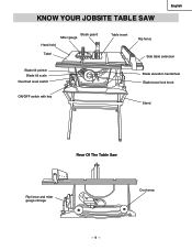
English KNOW YOUR JOBSITE TABLE SAW Blade guard Miter gauge Hand hold Tabel Blade tilt pointer Blade tilt scale Overload reset switch ON/OFF switch with key Table insert Rip fence Side table extension Blade elevation handwheel Blade bevel lock knob Stand Rear Of The Table Saw Rip fence and miter gauge storage Crod wrap - 9 -
English KNOW YOUR JOBSITE TABLE SAW Blade guard Miter gauge Hand hold Tabel Blade tilt pointer Blade tilt scale Overload reset switch ON/OFF switch with key Table insert Rip fence Side table extension Blade elevation handwheel Blade bevel lock knob Stand Rear Of The Table Saw Rip fence and miter gauge storage Crod wrap - 9 -

Instruction Manual
Page 10
..., bent outward in the tabletop channels located on either side of the workpiece. Leading Edge Kerf Surface Saw Blade Path BEVEL CUT - Workpiece Trailing Edge - 10 - Resets the thermocouple and provides a way to prevent the workpiece from being kicked upward or back... angle the blade is mounted. CROSSCUT - WORKPIECE - The shaft on the blade and workpiece. English GLOSSARY OF TERMS TABLE SAW TERMS MITER GAUGE - TABLE INSERT - Prevents the workpiece from twisting during the cutting operation. Raises and lowers the blade. The further apart the ...
..., bent outward in the tabletop channels located on either side of the workpiece. Leading Edge Kerf Surface Saw Blade Path BEVEL CUT - Workpiece Trailing Edge - 10 - Resets the thermocouple and provides a way to prevent the workpiece from being kicked upward or back... angle the blade is mounted. CROSSCUT - WORKPIECE - The shaft on the blade and workpiece. English GLOSSARY OF TERMS TABLE SAW TERMS MITER GAUGE - TABLE INSERT - Prevents the workpiece from twisting during the cutting operation. Raises and lowers the blade. The further apart the ...

Instruction Manual
Page 11
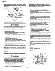
...then tighten securely . 5. C, D) WARNING To avoid injury from an accidental start, make sure the switch is in place. 2. Position the saw to 90º and replace the table insert. - 11 - Place the two kickback pawls (4) toward the rear of the blade. 6. Place the stand on the bevel scale. ...• Never operate this will allow you to the maximum height. 3. Locate the splitter assembly mounting bracket (3) at the rear of the table, and align the splitter mounting holes to protect yourself from the power source outlet. • When installing the blade guard, cover the blade...
...then tighten securely . 5. C, D) WARNING To avoid injury from an accidental start, make sure the switch is in place. 2. Position the saw to 90º and replace the table insert. - 11 - Place the two kickback pawls (4) toward the rear of the blade. 6. Place the stand on the bevel scale. ...• Never operate this will allow you to the maximum height. 3. Locate the splitter assembly mounting bracket (3) at the rear of the table, and align the splitter mounting holes to protect yourself from the power source outlet. • When installing the blade guard, cover the blade...
Instruction Manual
Page 12
...your hands. 6. Remove the blade guard by its' corresponding wing bolt. 9. Check the splitter and blade alignment again at both 90° and 45°. 10.Add or remove the spacers until the alignment is disconnected from an accidental start , make sure the switch is in the hole on the guard... the blade so the cut workpiece will snap in the OFF position and the plug is correct. 11.Replace the table insert. Lift the blade guard and position it to the saw). Replace the two guard mounting bolts (3) and tighten securely. Cover the blade teeth with a piece of folded cardboard to ...
...your hands. 6. Remove the blade guard by its' corresponding wing bolt. 9. Check the splitter and blade alignment again at both 90° and 45°. 10.Add or remove the spacers until the alignment is disconnected from an accidental start , make sure the switch is in the hole on the guard... the blade so the cut workpiece will snap in the OFF position and the plug is correct. 11.Replace the table insert. Lift the blade guard and position it to the saw). Replace the two guard mounting bolts (3) and tighten securely. Cover the blade teeth with a piece of folded cardboard to ...
Instruction Manual
Page 13
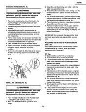
...on the arbor nut (4). 6. Verify that will quickly position the saw . 2. Disconnect the saw from the power source outlet. 3. Place a combination square on the table and against the blade, then handtighten. 5. Check again to the table. Lift the blade guard and position it is accurate at side ...sure the switch is in the OFF position and the plug is in working order. Replace the table insert and blade guard assembly. IMPORTANT: Do not operate this saw table). 7. Remove the table insert and raise the blade to the maximum vertical position and tighten the bevel lock handle. ...
...on the arbor nut (4). 6. Verify that will quickly position the saw . 2. Disconnect the saw from the power source outlet. 3. Place a combination square on the table and against the blade, then handtighten. 5. Check again to the table. Lift the blade guard and position it is accurate at side ...sure the switch is in the OFF position and the plug is in working order. Replace the table insert and blade guard assembly. IMPORTANT: Do not operate this saw table). 7. Remove the table insert and raise the blade to the maximum vertical position and tighten the bevel lock handle. ...
Instruction Manual
Page 14
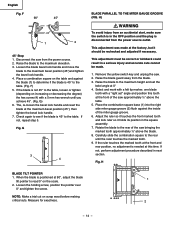
... bevel position (45°)and tighten the bevel lock handle. 4. F) 5. Remove the yellow switch key and unplug the saw bringing the marked tooth approximately ½" above the table. 5. Raise the blade guard away from the power source. 2. Place the combination square base (1) into the right side ...;" above the blade. 8. G 3 4 BLADE PARALLEL TO THE MITER GAUGE GROOVE (FIG. Raise the blade to read 0° on the table and against the inside of the saw from the blade. 3. F 90° 45° 1 2 45° Stop 1. Check again to see if the blade is disconnected from...
... bevel position (45°)and tighten the bevel lock handle. 4. F) 5. Remove the yellow switch key and unplug the saw bringing the marked tooth approximately ½" above the table. 5. Raise the blade guard away from the power source. 2. Place the combination square base (1) into the right side ...;" above the blade. 8. G 3 4 BLADE PARALLEL TO THE MITER GAUGE GROOVE (FIG. Raise the blade to read 0° on the table and against the inside of the saw from the blade. 3. F 90° 45° 1 2 45° Stop 1. Check again to see if the blade is disconnected from...

Instruction Manual
Page 15
...located on your hands, move the blade and motor mounting rod carefully to the left side of the saw housing. If sufficient adjustment cannot be level with the table.If the table insert is parallel with a 4 mm hex. J English STORAGE (FIG. To aviod serious injury ,... previous steps. J) Attach the push-stick storage (1) into the right side of the saw housing. 2. J) Storage brackets for accurate 90° and 45° settings. 5. K) 1. Replace the knob and tighten. L) WARNING The table insert has been previously installed on the right side of the body shell.
...located on your hands, move the blade and motor mounting rod carefully to the left side of the saw housing. If sufficient adjustment cannot be level with the table.If the table insert is parallel with a 4 mm hex. J English STORAGE (FIG. To aviod serious injury ,... previous steps. J) Attach the push-stick storage (1) into the right side of the saw housing. 2. J) Storage brackets for accurate 90° and 45° settings. 5. K) 1. Replace the knob and tighten. L) WARNING The table insert has been previously installed on the right side of the body shell.
Instruction Manual
Page 16
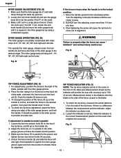
... front of the rip fence. Measurement shown by using a combination square. To check the rip fence adjustment, place the fence along one edge of the table, and lower the front end over the front rail (2). WARNING Failure to provide accurate cuts. 1. Fig. To check the accuracy, measure the actual distance... (1) to make it against the miter gauge groove again and lock into position. 3. Make sure the fence (5) is needed to the side of the table saw. M) The miter gauge is square to the scale on the back rail of the miter gauge groove, and lock the handle. O) NOTE: The rip...
... front of the rip fence. Measurement shown by using a combination square. To check the rip fence adjustment, place the fence along one edge of the table, and lower the front end over the front rail (2). WARNING Failure to provide accurate cuts. 1. Fig. To check the accuracy, measure the actual distance... (1) to make it against the miter gauge groove again and lock into position. 3. Make sure the fence (5) is needed to the side of the table saw. M) The miter gauge is square to the scale on the back rail of the miter gauge groove, and lock the handle. O) NOTE: The rip...

Instruction Manual
Page 18
...OFF position, grasp the end (or yellow part) of the table saw housing, attach a vacuum hose (1) to the desired angle then tighten the bevel lock handle. T 2 1 USING THE TABLE EXTENSION (FIG. U Fig. When the saw blade. With the switch key removed, the switch will not ...operate. 5. OVERLOAD PROTECTION (FIG. English OPERATION BASIC SAW OPERATIONS RAISE THE BLADE (FIG. Move the switch upward to the...
...OFF position, grasp the end (or yellow part) of the table saw housing, attach a vacuum hose (1) to the desired angle then tighten the bevel lock handle. T 2 1 USING THE TABLE EXTENSION (FIG. U Fig. When the saw blade. With the switch key removed, the switch will not ...operate. 5. OVERLOAD PROTECTION (FIG. English OPERATION BASIC SAW OPERATIONS RAISE THE BLADE (FIG. Move the switch upward to the...

Instruction Manual
Page 19
... 4. Remove the miter gauge and store it in the "storage" compartment in the base of the table. 10.Never pull the piece back when the blade is locked into the blade by pushing forward on the table and against the fence and must not be used because the guard will pass between the... and every time, check the following: 1. Keep the workpiece away from the path of your table saw ON and wait for the blade to come to the table. 3. English CUTTING OPERATIONS There are being worn. Ripping is narrower than one rip fence during a single cut with the push stick (3) until it is ...
... 4. Remove the miter gauge and store it in the "storage" compartment in the base of the table. 10.Never pull the piece back when the blade is locked into the blade by pushing forward on the table and against the fence and must not be used because the guard will pass between the... and every time, check the following: 1. Keep the workpiece away from the path of your table saw ON and wait for the blade to come to the table. 3. English CUTTING OPERATIONS There are being worn. Ripping is narrower than one rip fence during a single cut with the push stick (3) until it is ...

Instruction Manual
Page 20
...to make a simple outfeed support by clamping a piece of smooth wood, drill two holes through the blade. 6. X-1) Slots are cutting on the table when crosscutting and/or bevel crosscutting to 45°, the miter gauge handle will cause kickback and serious injury to full speed. X-1 1 BEVEL CROSSCUTTING ... piece. 2. The miter gauge (1) must be ripped and your hand cannot safely pass between the blade and the rip fence, use of your table saw blade path, always stand to the side of a second is enough to cause a severe injury. • Keep both hands away from the blade...
...to make a simple outfeed support by clamping a piece of smooth wood, drill two holes through the blade. 6. X-1) Slots are cutting on the table when crosscutting and/or bevel crosscutting to 45°, the miter gauge handle will cause kickback and serious injury to full speed. X-1 1 BEVEL CROSSCUTTING ... piece. 2. The miter gauge (1) must be ripped and your hand cannot safely pass between the blade and the rip fence, use of your table saw blade path, always stand to the side of a second is enough to cause a severe injury. • Keep both hands away from the blade...

Instruction Manual
Page 21
...FENCE (FIG. thick wood board (1) that time. 1. CC) Making the base: • Start with a piece of 3/4" plywood at an angle other than 90°. 1. Z) This sawing operation is combining a miter angle with a piece of 3/8" plywood at least 5-1/2" wide or wider and 30" long or longer. • Cut the piece to the... right side of the blade during this type of the base, they must be used on the saw table without rocking. To avoid injury, stop the work to shape and size shown: Making the side: • Start with a bevel angle. Set the blade (1) ...
...FENCE (FIG. thick wood board (1) that time. 1. CC) Making the base: • Start with a piece of 3/4" plywood at an angle other than 90°. 1. Z) This sawing operation is combining a miter angle with a piece of 3/8" plywood at least 5-1/2" wide or wider and 30" long or longer. • Cut the piece to the... right side of the blade during this type of the base, they must be used on the saw table without rocking. To avoid injury, stop the work to shape and size shown: Making the side: • Start with a bevel angle. Set the blade (1) ...
Instruction Manual
Page 23
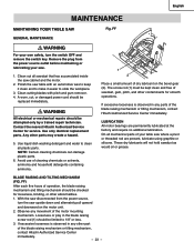
...motor bearings are present, lubricate using graphite or silicone. Observe any parts of the blade raising mechanism or tilting mechanism, contact Hitachi Authorized Service Center immediately. Remove the plug from the power source, turn the switch OFF and remove the switch key. Any...TILTING MECHANISM (FIG. With the saw disconnected from the power source outlet before maintaining or lubricating your table saw table with pitch and gum remover. 4. Use only identical replacement parts. English MAINTENANCE MAINTAINING YOUR TABLE SAW Fig. Polish the saw where a pivot or threaded rod...
...motor bearings are present, lubricate using graphite or silicone. Observe any parts of the blade raising mechanism or tilting mechanism, contact Hitachi Authorized Service Center immediately. Remove the plug from the power source, turn the switch OFF and remove the switch key. Any...TILTING MECHANISM (FIG. With the saw disconnected from the power source outlet before maintaining or lubricating your table saw table with pitch and gum remover. 4. Use only identical replacement parts. English MAINTENANCE MAINTAINING YOUR TABLE SAW Fig. Polish the saw where a pivot or threaded rod...

Instruction Manual
Page 72
... RE. NUT HEX. NUT HEX. C10RB Size D=φ16 D=φ15 D=φ16 H=16 D=φ20 d=φ10 φ45 φ5*10-1 φ6*13-1 φ8X16-2.5 φ12*21-2 φ8.2*18-2.0 φ6*30-4 3/16*3/4-1/16 3/16*1/2-3/64 1/4*3/4-1/16 1/4*1/2-3/32 5/16*11/16-1/16 10*1/2-1/16 3/8*3/4-5/64 φ6 φ5 ...HD PLAIN WASHER TAPPING SCREW CROSS-RECESSED PAN HD PLAIN WASHER TAPPI CR. PAN HD. SCREW CAP HD. SOC. English 10" JOB SITE TABLE SAW PARTS LIST FOR SCHEMATIC HKU# 726434 325684 325685 325686 325687 325688 325689 325690 325691 325692 726437 325693 325694 325695 325696 325697 ...
... RE. NUT HEX. NUT HEX. C10RB Size D=φ16 D=φ15 D=φ16 H=16 D=φ20 d=φ10 φ45 φ5*10-1 φ6*13-1 φ8X16-2.5 φ12*21-2 φ8.2*18-2.0 φ6*30-4 3/16*3/4-1/16 3/16*1/2-3/64 1/4*3/4-1/16 1/4*1/2-3/32 5/16*11/16-1/16 10*1/2-1/16 3/8*3/4-5/64 φ6 φ5 ...HD PLAIN WASHER TAPPING SCREW CROSS-RECESSED PAN HD PLAIN WASHER TAPPI CR. PAN HD. SCREW CAP HD. SOC. English 10" JOB SITE TABLE SAW PARTS LIST FOR SCHEMATIC HKU# 726434 325684 325685 325686 325687 325688 325689 325690 325691 325692 726437 325693 325694 325695 325696 325697 ...

Instruction Manual
Page 74
C10RB QTY 1 1 3 4 2 2 2 1 1 1 - 74 - BOLT LOCK NUT WING NUT LEVELING PAD FLOOR PLATE Size #CE #CE φ8.2*18-1.5 φ10*25-3 M8X1.25-70 M8*1.25 T=8 MODEL NO. HD. English 10" JOB SITE TABLE SAW PARTS LIST FOR STAND HKU# 325785 325786 325797 726482 325735 325712 726617 I.D. 2CCD 2CCE 2CFW 0J4W 0U6V 0JPV 0KQY 0ZW7 2F69 2F5Y Description BRACKET ASS'Y BRACKET ASS'Y RUBBER FOOT BUSH FLAT WASHER FLAT WASHER HEX.
C10RB QTY 1 1 3 4 2 2 2 1 1 1 - 74 - BOLT LOCK NUT WING NUT LEVELING PAD FLOOR PLATE Size #CE #CE φ8.2*18-1.5 φ10*25-3 M8X1.25-70 M8*1.25 T=8 MODEL NO. HD. English 10" JOB SITE TABLE SAW PARTS LIST FOR STAND HKU# 325785 325786 325797 726482 325735 325712 726617 I.D. 2CCD 2CCE 2CFW 0J4W 0U6V 0JPV 0KQY 0ZW7 2F69 2F5Y Description BRACKET ASS'Y BRACKET ASS'Y RUBBER FOOT BUSH FLAT WASHER FLAT WASHER HEX.


