Instruction Manual
Page 3
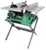
... out microscopic particles. Before using your exposure to these rules could result in a well-ventilated area and work with Extension ......... 24-1/2" Blade Size 10" Rip Scale YES Rip Fence YES Miter Gauge YES Maximum Cut Depth @ 90 3-1/8" Maximum Cut Depth @ 45 2-1/4" Maximum Dado Cut Width 13...120 Volt operation. To avoid shock or fire, replace power cord immediately if it is worn, cut or damaged in any way. This table saw , it is critical that are : • Lead based paints • Crystalline silica from bricks, cement and other masonry products • Arsenic...
... out microscopic particles. Before using your exposure to these rules could result in a well-ventilated area and work with Extension ......... 24-1/2" Blade Size 10" Rip Scale YES Rip Fence YES Miter Gauge YES Maximum Cut Depth @ 90 3-1/8" Maximum Cut Depth @ 45 2-1/4" Maximum Dado Cut Width 13...120 Volt operation. To avoid shock or fire, replace power cord immediately if it is worn, cut or damaged in any way. This table saw , it is critical that are : • Lead based paints • Crystalline silica from bricks, cement and other masonry products • Arsenic...

Instruction Manual
Page 4
... SAFETY IS INVOLVED! Serious injury could cause serious injury when they break. 25. DO NOT use of any other conditions that is not designed. 10. Don't force the tool or attachment to a complete stop. 17. DISCONNECT TOOLS before turning ON. 16. MAKE WORKSHOP CHILDPROOF with adequate dust ... use your power tool. NOTE: Glasses or goggles not in serious injury or damage to the table saw , it is recommended. English POWER TOOL SAFETY WARNING Before using your table saw . READ and become familiar with ANSI safety standard Z87.1. It means BE ALERT! NEVER LEAVE TOOL...
... SAFETY IS INVOLVED! Serious injury could cause serious injury when they break. 25. DO NOT use of any other conditions that is not designed. 10. Don't force the tool or attachment to a complete stop. 17. DISCONNECT TOOLS before turning ON. 16. MAKE WORKSHOP CHILDPROOF with adequate dust ... use your power tool. NOTE: Glasses or goggles not in serious injury or damage to the table saw , it is recommended. English POWER TOOL SAFETY WARNING Before using your table saw . READ and become familiar with ANSI safety standard Z87.1. It means BE ALERT! NEVER LEAVE TOOL...
Instruction Manual
Page 5
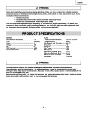
Always be used to clean plastic parts. 16. ALWAYS HOLD WORK FIRMLY against the direction of the saw blade. 15. Refer to a complete stop. 10. WARNING: FREEHAND CUTTING IS THE MAJOR CAUSE OF KICKBACK AND FINGER/ HAND AMPUTATIONS. 5. AVOID KICKBACKS (work . Refer to clean plastic ... along the fence. 14. DO NOT USE a molding head with the path of your table saw to the dust port for long or wide workpieces. 13. Remove sawdust frequently. English TABLE SAW SAFETY 1. ALWAYS USE SAW BLADE GUARD, splitter and anti-kickback pawls for any cutting operations. ALWAYS USE a push ...
Always be used to clean plastic parts. 16. ALWAYS HOLD WORK FIRMLY against the direction of the saw blade. 15. Refer to a complete stop. 10. WARNING: FREEHAND CUTTING IS THE MAJOR CAUSE OF KICKBACK AND FINGER/ HAND AMPUTATIONS. 5. AVOID KICKBACKS (work . Refer to clean plastic ... along the fence. 14. DO NOT USE a molding head with the path of your table saw to the dust port for long or wide workpieces. 13. Remove sawdust frequently. English TABLE SAW SAFETY 1. ALWAYS USE SAW BLADE GUARD, splitter and anti-kickback pawls for any cutting operations. ALWAYS USE a push ...

Instruction Manual
Page 6
... only) Ampere Rating Total length of Cord More Than Not More Than 25ft. 50ft. 100ft. 150ft. 0 6 18 16 16 14 6 10 18 16 14 12 10 12 16 16 14 12 12 16 14 12 Not Applicable GUIDELINES FOR EXTENSION CORDS Any extension cord used for 120V operation. The...Adapter Make sure this tool. English ELECTRICAL REQUIREMENTS AND SAFETY POWER SUPPLY REQUIREMENTS WARNING To avoid electrical hazards, fire hazards or damage to the table saw 's plug. Make sure the extension cord is the equipment grounding conductor. An undersized cord will not fit the receptacle, have it to 16...
... only) Ampere Rating Total length of Cord More Than Not More Than 25ft. 50ft. 100ft. 150ft. 0 6 18 16 16 14 6 10 18 16 14 12 10 12 16 16 14 12 12 16 14 12 Not Applicable GUIDELINES FOR EXTENSION CORDS Any extension cord used for 120V operation. The...Adapter Make sure this tool. English ELECTRICAL REQUIREMENTS AND SAFETY POWER SUPPLY REQUIREMENTS WARNING To avoid electrical hazards, fire hazards or damage to the table saw 's plug. Make sure the extension cord is the equipment grounding conductor. An undersized cord will not fit the receptacle, have it to 16...

Instruction Manual
Page 7
... PARTS ITEM A B C D E F G H I J K L DESCRIPTION QUANTITY Table saw assembly 1 Blade guard and splitter ass'y 1 Rip fence 1 Dado table insert 1 Miter gauge 1 Push stick 1 Blade wrench 1 Push stick storage 1 Blade 1 Handwheel handle 1 Hex wrenchs 2 Blade guard hardware bag ass...recommended by Store. Wipe all parts thoroughly with the illustration on the next page and the "Table of Loose Parts" to make assembly easier, keep contents of automobile wax to assemble the table saw . • Do not modify this power tool. Check each part with a clean dry...
... PARTS ITEM A B C D E F G H I J K L DESCRIPTION QUANTITY Table saw assembly 1 Blade guard and splitter ass'y 1 Rip fence 1 Dado table insert 1 Miter gauge 1 Push stick 1 Blade wrench 1 Push stick storage 1 Blade 1 Handwheel handle 1 Hex wrenchs 2 Blade guard hardware bag ass...recommended by Store. Wipe all parts thoroughly with the illustration on the next page and the "Table of Loose Parts" to make assembly easier, keep contents of automobile wax to assemble the table saw . • Do not modify this power tool. Check each part with a clean dry...
Instruction Manual
Page 9
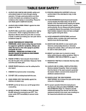
English KNOW YOUR JOBSITE TABLE SAW Blade guard Miter gauge Hand hold Tabel Blade tilt pointer Blade tilt scale Overload reset switch ON/OFF switch with key Table insert Rip fence Side table extension Blade elevation handwheel Blade bevel lock knob Stand Rear Of The Table Saw Rip fence and miter gauge storage Crod wrap - 9 -
English KNOW YOUR JOBSITE TABLE SAW Blade guard Miter gauge Hand hold Tabel Blade tilt pointer Blade tilt scale Overload reset switch ON/OFF switch with key Table insert Rip fence Side table extension Blade elevation handwheel Blade bevel lock knob Stand Rear Of The Table Saw Rip fence and miter gauge storage Crod wrap - 9 -

Instruction Manual
Page 10
CROSSCUT - OVERLOAD RESET SWITCH - HEEL - TABLE SCALE - ANTI-KICKBACK PAWLS - SPLITTER - SET - Tilts the blade to any angle between two saw blade tips, bent outward in opposite directions to each other proper device to the tabletop. Leading Edge Kerf Surface Saw Blade Path BEVEL CUT - Workpiece Trailing Edge - 10 - A cut , to 45° for changing...
CROSSCUT - OVERLOAD RESET SWITCH - HEEL - TABLE SCALE - ANTI-KICKBACK PAWLS - SPLITTER - SET - Tilts the blade to any angle between two saw blade tips, bent outward in opposite directions to each other proper device to the tabletop. Leading Edge Kerf Surface Saw Blade Path BEVEL CUT - Workpiece Trailing Edge - 10 - A cut , to 45° for changing...

Instruction Manual
Page 11
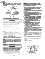
...holes of the stand to the stand using the four handle (1) then tighten securely . 5. B 2 1 Fig. English ASSEMBLY AND ADJUSTMENTS ASSEMBLE THE TABLE SAW TO THE STAND (Fig. ASSEMBLE THE HANDWHEEL HANDLE (FIG. Loosen the blade lock handle (2) do not pull on handle just turn and move the ... on the bottom flange of the blade. 6. C) 1. With the blade elevation handwheel (1), raise the blade to 90º and replace the table insert. - 11 - Place the two kickback pawls (4) toward the rear of folded cardboard to protect yourself from the power source outlet. • When...
...holes of the stand to the stand using the four handle (1) then tighten securely . 5. B 2 1 Fig. English ASSEMBLY AND ADJUSTMENTS ASSEMBLE THE TABLE SAW TO THE STAND (Fig. ASSEMBLE THE HANDWHEEL HANDLE (FIG. Loosen the blade lock handle (2) do not pull on handle just turn and move the ... on the bottom flange of the blade. 6. C) 1. With the blade elevation handwheel (1), raise the blade to 90º and replace the table insert. - 11 - Place the two kickback pawls (4) toward the rear of folded cardboard to protect yourself from the power source outlet. • When...
Instruction Manual
Page 12
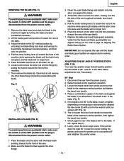
Remove the table insert. 2. Tighten the bevel lock handle. 5. Lift the blade guard and position it to the maximum height. 3. Position them over the blade to the saw). Replace the two guard mounting bolts (3) and tighten securely. Fig. D) 54 2 3 WARNING To avoid injury from the power source ...(1) and splitter (2) are not correctly aligned: a. b. Check the splitter and blade alignment again at both 90° and 45°. 10.Add or remove the spacers until the alignment is assembled before rising the blade. If the blade and splitter are correctly aligned, lay a ...
Remove the table insert. 2. Tighten the bevel lock handle. 5. Lift the blade guard and position it to the maximum height. 3. Position them over the blade to the saw). Replace the two guard mounting bolts (3) and tighten securely. Fig. D) 54 2 3 WARNING To avoid injury from the power source ...(1) and splitter (2) are not correctly aligned: a. b. Check the splitter and blade alignment again at both 90° and 45°. 10.Add or remove the spacers until the alignment is assembled before rising the blade. If the blade and splitter are correctly aligned, lay a ...
Instruction Manual
Page 13
... degree) the hex screw (3) with the blade teeth pointing forward to the front of the saw from the power source. 2. If the blade is 90° to the table, loosen or tighten (depending on the table and against the inner flange. - 13 - Lastly, check the bevel angle scale....machine while spinning the blade until the latch locks into place and the blade will quickly position the saw table). 7. Place the wrench on the arbor nut (4). 6. If not, repeat step 5. 8. Remove the table insert and raise the blade to the maximum elevation. 3. Pull the motor locking lever (1) toward ...
... degree) the hex screw (3) with the blade teeth pointing forward to the front of the saw from the power source. 2. If the blade is 90° to the table, loosen or tighten (depending on the table and against the inner flange. - 13 - Lastly, check the bevel angle scale....machine while spinning the blade until the latch locks into place and the blade will quickly position the saw table). 7. Place the wrench on the arbor nut (4). 6. If not, repeat step 5. 8. Remove the table insert and raise the blade to the maximum elevation. 3. Pull the motor locking lever (1) toward ...
Instruction Manual
Page 14
... outlet. Remove the yellow switch key and unplug the saw from the blade. 3. Carefully slide the combination square to the table. (Fig. NOTE: Make a trial cut on the scale. 1 2. Place a combination square on the table and against the inside of the saw approximately ½" above the blade. 8. This adjustment ... front marked tooth and lock ruler so it should be made at the front of the saw bringing the marked tooth approximately ½" above the table. 5. Rotate the blade to the table. The, re-loosen the bevel lock handle and reset the blade at this tooth at ...
... outlet. Remove the yellow switch key and unplug the saw from the blade. 3. Carefully slide the combination square to the table. (Fig. NOTE: Make a trial cut on the scale. 1 2. Place a combination square on the table and against the inside of the saw approximately ½" above the blade. 8. This adjustment ... front marked tooth and lock ruler so it should be made at the front of the saw bringing the marked tooth approximately ½" above the table. 5. Rotate the blade to the table. The, re-loosen the bevel lock handle and reset the blade at this tooth at ...

Instruction Manual
Page 15
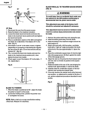
...the blade does not hit the table insert or other parts when at they are set for the rip fence (3) and miter gauge (4) are not the same, remove the combination square and loosen the four adjusting screws (1) on all four corners of the saw housing. J) Storage brackets for ... as much as described in the prior section. 4. If sufficient adjustment cannot be level with the table.If the table insert is flush with the table top surface on the top of the saw housing. 2. Re-tighten all previous steps. J English STORAGE (FIG. J, K) Rip fence and miter gauge ...
...the blade does not hit the table insert or other parts when at they are set for the rip fence (3) and miter gauge (4) are not the same, remove the combination square and loosen the four adjusting screws (1) on all four corners of the saw housing. J) Storage brackets for ... as much as described in the prior section. 4. If sufficient adjustment cannot be level with the table.If the table insert is flush with the table top surface on the top of the saw housing. 2. Re-tighten all previous steps. J English STORAGE (FIG. J, K) Rip fence and miter gauge ...
Instruction Manual
Page 16
...upward to properly align the fence can cause " kickback" and serious injury could occur. Over-tightening the screw will slide freely through the table top grooves. 2. To change the position of alignment. If there is parallel to provide accurate cuts. 1. O 2. To check the accuracy... screw more than 1/4 turn the gauge body (3) to the miter gauge bar by the indicator will stop at 0º on the back rail of the table saw. WARNING Failure to the unlocked position. Fig. N 1 5 4 6 3 4 2 2 3 RIP FENCE ADJUSTMENT (FIG. N) 1. For adjustments, position the fence...
...upward to properly align the fence can cause " kickback" and serious injury could occur. Over-tightening the screw will slide freely through the table top grooves. 2. To change the position of alignment. If there is parallel to provide accurate cuts. 1. O 2. To check the accuracy... screw more than 1/4 turn the gauge body (3) to the miter gauge bar by the indicator will stop at 0º on the back rail of the table saw. WARNING Failure to the unlocked position. Fig. N 1 5 4 6 3 4 2 2 3 RIP FENCE ADJUSTMENT (FIG. N) 1. For adjustments, position the fence...

Instruction Manual
Page 18
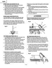
... handwheel (1) to the desired blade height, and then tighten the bevel lock handle (2) to the desired dimension using the scale on . S) This saw . Fig. Unlock the extension table, and slide the table with the hose in place unless the vacuum is running, it out. 4. R) To raise or lower the blade, turn the...THE BLADE Two methods are available for the motor to cool, the push in the OFF position, grasp the end (or yellow part) of the table saw has an overload relay button (3) that resets the motor after it shuts off due to the ON position. 2. To lock the switch in on the...
... handwheel (1) to the desired blade height, and then tighten the bevel lock handle (2) to the desired dimension using the scale on . S) This saw . Fig. Unlock the extension table, and slide the table with the hose in place unless the vacuum is running, it out. 4. R) To raise or lower the blade, turn the...THE BLADE Two methods are available for the motor to cool, the push in the OFF position, grasp the end (or yellow part) of the table saw has an overload relay button (3) that resets the motor after it shuts off due to the ON position. 2. To lock the switch in on the...

Instruction Manual
Page 19
...V 1 NOTE: Always use of the workpiece. 4. Keep your thumbs touch the front edge of your table saw ON and wait for the blade to come to the arbor. 2. W) 9. W 1. Turn the saw to the miter gauge groove. 4. Slowly feed the workpiece into position & is cutting along the length ... is turning. Fig. The push stick (3) should always be used . (Fig. When the blade completely stops, you can greatly increase the likelihood of the table. 10.Never pull the piece back when the blade is enough to cause a severe injury. • Keep both of cuts: ripping and crosscutting. V) 2 - ...
...V 1 NOTE: Always use of the workpiece. 4. Keep your thumbs touch the front edge of your table saw ON and wait for the blade to come to the arbor. 2. W) 9. W 1. Turn the saw to the miter gauge groove. 4. Slowly feed the workpiece into position & is cutting along the length ... is turning. Fig. The push stick (3) should always be used . (Fig. When the blade completely stops, you can greatly increase the likelihood of the table. 10.Never pull the piece back when the blade is enough to cause a severe injury. • Keep both of cuts: ripping and crosscutting. V) 2 - ...

Instruction Manual
Page 20
...blade during ripping operations. This will hit the blade guard. Tighten miter lock handle at against the face of cut if used on the table. 2. RIPPING SMALL PIECES To avoid injury from the blade. 4. CROSSCUTTING (FIG. Move the workpiece to the user can make it is... Always work to pull the workpiece backwards during a cutting operation. The miter gauge (1) must be ripped and your table saw to cut location. Hold workpiece firmly against the table. NOTE: When tilting the blade to 45°, the miter gauge handle will cause kickback and serious injury to ...
...blade during ripping operations. This will hit the blade guard. Tighten miter lock handle at against the face of cut if used on the table. 2. RIPPING SMALL PIECES To avoid injury from the blade. 4. CROSSCUTTING (FIG. Move the workpiece to the user can make it is... Always work to pull the workpiece backwards during a cutting operation. The miter gauge (1) must be ripped and your table saw to cut location. Hold workpiece firmly against the table. NOTE: When tilting the blade to 45°, the miter gauge handle will cause kickback and serious injury to ...

Instruction Manual
Page 21
... the miter gauge locking handle. 3. Set the miter gauge (3) to the right side of the blade during this type of cut if used on the saw table without rocking. Fig. Set the miter gauge (3) at that is combining a miter angle with a piece of 3/8" plywood at least 5-1/2" wide or wider and 30" ... face of the base, they must be in the right side groove (2) of the fence and the table. Hold the workpiece (2) firmly against the face of the rip fence (2). 1. Fig. Z) This sawing operation is as long as crosscutting except the miter gauge is locked at and smooth enough to rest...
... the miter gauge locking handle. 3. Set the miter gauge (3) to the right side of the blade during this type of cut if used on the saw table without rocking. Fig. Set the miter gauge (3) at that is combining a miter angle with a piece of 3/8" plywood at least 5-1/2" wide or wider and 30" ... face of the base, they must be in the right side groove (2) of the fence and the table. Hold the workpiece (2) firmly against the face of the rip fence (2). 1. Fig. Z) This sawing operation is as long as crosscutting except the miter gauge is locked at and smooth enough to rest...
Instruction Manual
Page 23
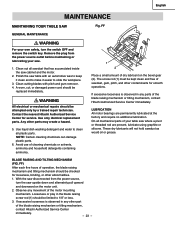
...TABLE SAW Fig. Remove the plug from the power source, turn the switch OFF and remove the switch key. Clean cutting blades with an automotive wax to keep it clean and to make it easier to slide the workpiece. 3. A worn, cut, or damaged power cord should be replaced immediately. Contact the nearest Hitachi... only by a trained repair technician. With the saw disconnected from the power source outlet before maintaining or lubricating your saw table with pitch and gum remover. 4. FF GENERAL MAINTENANCE WARNING For your table saw cabinet and the motor. 2. Use only identical ...
...TABLE SAW Fig. Remove the plug from the power source, turn the switch OFF and remove the switch key. Clean cutting blades with an automotive wax to keep it clean and to make it easier to slide the workpiece. 3. A worn, cut, or damaged power cord should be replaced immediately. Contact the nearest Hitachi... only by a trained repair technician. With the saw disconnected from the power source outlet before maintaining or lubricating your saw table with pitch and gum remover. 4. FF GENERAL MAINTENANCE WARNING For your table saw cabinet and the motor. 2. Use only identical ...

Instruction Manual
Page 72
... CR.-RE. SCREW CR. PAN HD. PAN HD. TAPPING SCREW CR. TAPPING SCREW CR. TRUSS HD. C10RB Size D=φ16 D=φ15 D=φ16 H=16 D=φ20 d=φ10 φ45 φ5*10-1 φ6*13-1 φ8X16-2.5 φ12*21-2 φ8.2*18-2.0 φ6*30-4 3/16*3/4-1/16 3/... 1 2 325840 2ETF LABEL 1 1 - 72 - SCREW HEX. PAN HD. TRUSS HD. SCREW HEX. SCREW CR. NUT HEX. HD. HD. English 10" JOB SITE TABLE SAW PARTS LIST FOR SCHEMATIC HKU# 726434 325684 325685 325686 325687 325688 325689 325690 325691 325692 726437 325693 325694 325695 325696 325697 325698 325699 726450...
... CR.-RE. SCREW CR. PAN HD. PAN HD. TAPPING SCREW CR. TAPPING SCREW CR. TRUSS HD. C10RB Size D=φ16 D=φ15 D=φ16 H=16 D=φ20 d=φ10 φ45 φ5*10-1 φ6*13-1 φ8X16-2.5 φ12*21-2 φ8.2*18-2.0 φ6*30-4 3/16*3/4-1/16 3/... 1 2 325840 2ETF LABEL 1 1 - 72 - SCREW HEX. PAN HD. TRUSS HD. SCREW HEX. SCREW CR. NUT HEX. HD. HD. English 10" JOB SITE TABLE SAW PARTS LIST FOR SCHEMATIC HKU# 726434 325684 325685 325686 325687 325688 325689 325690 325691 325692 726437 325693 325694 325695 325696 325697 325698 325699 726450...

Instruction Manual
Page 74
English 10" JOB SITE TABLE SAW PARTS LIST FOR STAND HKU# 325785 325786 325797 726482 325735 325712 726617 I.D. 2CCD 2CCE 2CFW 0J4W 0U6V 0JPV 0KQY 0ZW7 2F69 2F5Y Description BRACKET ASS'Y BRACKET ASS'Y RUBBER FOOT BUSH FLAT WASHER FLAT WASHER HEX. C10RB QTY 1 1 3 4 2 2 2 1 1 1 - 74 - HD. BOLT LOCK NUT WING NUT LEVELING PAD FLOOR PLATE Size #CE #CE φ8.2*18-1.5 φ10*25-3 M8X1.25-70 M8*1.25 T=8 MODEL NO.
English 10" JOB SITE TABLE SAW PARTS LIST FOR STAND HKU# 325785 325786 325797 726482 325735 325712 726617 I.D. 2CCD 2CCE 2CFW 0J4W 0U6V 0JPV 0KQY 0ZW7 2F69 2F5Y Description BRACKET ASS'Y BRACKET ASS'Y RUBBER FOOT BUSH FLAT WASHER FLAT WASHER HEX. C10RB QTY 1 1 3 4 2 2 2 1 1 1 - 74 - HD. BOLT LOCK NUT WING NUT LEVELING PAD FLOOR PLATE Size #CE #CE φ8.2*18-1.5 φ10*25-3 M8X1.25-70 M8*1.25 T=8 MODEL NO.


