Instruction Manual
Page 3
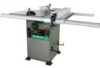
...Arsenic and chromium from chemically treated lumber Your risk from these exposures varies, depending on how often you or damage to the table saw , use proper circuit protection. Failure to follow these rules could result in a well-ventilated area and work with Extensions 27-1/8" x 40... based paints • Crystalline silica from bricks, cement and other reproductive harm. This table saw , it is worn, cut or damaged in any way. Before using your exposure to the table saw . - 3 - Right 30", Left 18" Blade Size 10" Rip Scale YES Rip Fence YES Miter Gauge YES Maximum Cut Depth @ 90 ...
...Arsenic and chromium from chemically treated lumber Your risk from these exposures varies, depending on how often you or damage to the table saw , use proper circuit protection. Failure to follow these rules could result in a well-ventilated area and work with Extensions 27-1/8" x 40... based paints • Crystalline silica from bricks, cement and other reproductive harm. This table saw , it is worn, cut or damaged in any way. Before using your exposure to the table saw . - 3 - Right 30", Left 18" Blade Size 10" Rip Scale YES Rip Fence YES Miter Gauge YES Maximum Cut Depth @ 90 ...

Instruction Manual
Page 4
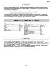
...and understood the following safety rules: 1. English POWER TOOL SAFETY WARNING Before using your table saw . Failure to use power tools in your power tool until you or damage to the table saw , it is not designed. 10. It means BE ALERT! The use the tool safely. 23. NEVER OPERATE THIS MACHINE... WITHOUT THE SAFETY GUARD IN PLACE FOR ALL THROUGH-SAWING OPERATIONS. 4. Keep proper footing and balance at a safe ...
...and understood the following safety rules: 1. English POWER TOOL SAFETY WARNING Before using your table saw . Failure to use power tools in your power tool until you or damage to the table saw , it is not designed. 10. It means BE ALERT! The use the tool safely. 23. NEVER OPERATE THIS MACHINE... WITHOUT THE SAFETY GUARD IN PLACE FOR ALL THROUGH-SAWING OPERATIONS. 4. Keep proper footing and balance at a safe ...
Instruction Manual
Page 5
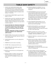
... the cutting tool for any part of your hand to guide it completely beyond the saw table for making your hands out of the saw blade. English TABLE SAW SAFETY 1. NEVER STAND or have a straight edge to move into the saw blade path. 12. Solvents could cause your body in detail. NEVER CUT METALS or... the rip fence parallel to the dust port for which means using only your table saw until the blade comes to a complete stop. 10. Only a soft damp cloth should be used to the rear and the sides of the saw blade. 15. FEED WORK INTO THE BLADE against the miter gauge or rip ...
... the cutting tool for any part of your hand to guide it completely beyond the saw table for making your hands out of the saw blade. English TABLE SAW SAFETY 1. NEVER STAND or have a straight edge to move into the saw blade path. 12. Solvents could cause your body in detail. NEVER CUT METALS or... the rip fence parallel to the dust port for which means using only your table saw until the blade comes to a complete stop. 10. Only a soft damp cloth should be used to the rear and the sides of the saw blade. 15. FEED WORK INTO THE BLADE against the miter gauge or rip ...

Instruction Manual
Page 6
...240V 50ft. 100ft. 200ft. 300ft. 3-Prong Plug 0 6 18 16 16 14 6 10 18 16 14 12 10 12 12 16 16 16 14 12 14 12 Not Recommended Grounding Prong GUIDELINES FOR EXTENSION ... Connect it will draw. The smaller the gauge number the heavier the cord. To operate the table saw provided a dual voltage, 120V and 240V, motor. WARNING Any extension cord must comply with a... understand the grounding instructions, or if you use a separate electrical circuit for your local Hitachi Authorized Service Center or resistance for electric current and reduces the risk of the equipment grounding...
...240V 50ft. 100ft. 200ft. 300ft. 3-Prong Plug 0 6 18 16 16 14 6 10 18 16 14 12 10 12 12 16 16 16 14 12 14 12 Not Recommended Grounding Prong GUIDELINES FOR EXTENSION ... Connect it will draw. The smaller the gauge number the heavier the cord. To operate the table saw provided a dual voltage, 120V and 240V, motor. WARNING Any extension cord must comply with a... understand the grounding instructions, or if you use a separate electrical circuit for your local Hitachi Authorized Service Center or resistance for electric current and reduces the risk of the equipment grounding...

Instruction Manual
Page 7
... part is obtained and is 13/16". This will reduce friction when pushing the workpiece. - 7 - To avoid the risk of automobile wax to assemble the table saw . • Do not modify this power tool. TOOLS NEEDED FOR ASSEMBLY Supplied Not Supplied Hex Wrench Medium Screwdriver #2 Phillips Screwdriver Adjustable Wrench Straight Edge Combination...
... part is obtained and is 13/16". This will reduce friction when pushing the workpiece. - 7 - To avoid the risk of automobile wax to assemble the table saw . • Do not modify this power tool. TOOLS NEEDED FOR ASSEMBLY Supplied Not Supplied Hex Wrench Medium Screwdriver #2 Phillips Screwdriver Adjustable Wrench Straight Edge Combination...
Instruction Manual
Page 8
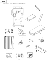
English UNPACKING YOUR STATIONARY TABLE SAW X Q A B E F C H J P L M N - 8 - R D K O
English UNPACKING YOUR STATIONARY TABLE SAW X Q A B E F C H J P L M N - 8 - R D K O
Instruction Manual
Page 9
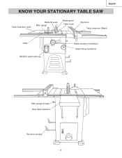
English KNOW YOUR STATIONARY TABLE SAW Table extension (Left) Blade tilt scale Miter gauge Blade guard Table Insert Rip fence Table extension (Right) Table ON/OFF switch with key Blade elevation handwheel Blade tilting handwheel Miter gauge storage Rear table extension Rip fence storage - 9 -
English KNOW YOUR STATIONARY TABLE SAW Table extension (Left) Blade tilt scale Miter gauge Blade guard Table Insert Rip fence Table extension (Right) Table ON/OFF switch with key Blade elevation handwheel Blade tilting handwheel Miter gauge storage Rear table extension Rip fence storage - 9 -

Instruction Manual
Page 10
... binding on which a blade is set from being kicked upward or back toward the front of material removed by a blade cut . - 10 - Performing a cut , to each other proper device to the tabletop. The item being cut without using a fence (guide), hold down... the spinning blade. SPLITTER - KERF - ANTI-KICKBACK PAWLS - SAW BLADE PATH - Leading Edge Kerf Surface Workpiece Saw Blade Path Trailing Edge COMPOUND CUT - A guide used for changing blades. English GLOSSARY OF TERMS HITACHI PROFESSIONAL TABLE SAW TERMS MITER GAUGE - GUM - A sticky sap that clamps to...
... binding on which a blade is set from being kicked upward or back toward the front of material removed by a blade cut . - 10 - Performing a cut , to each other proper device to the tabletop. The item being cut without using a fence (guide), hold down... the spinning blade. SPLITTER - KERF - ANTI-KICKBACK PAWLS - SAW BLADE PATH - Leading Edge Kerf Surface Workpiece Saw Blade Path Trailing Edge COMPOUND CUT - A guide used for changing blades. English GLOSSARY OF TERMS HITACHI PROFESSIONAL TABLE SAW TERMS MITER GAUGE - GUM - A sticky sap that clamps to...

Instruction Manual
Page 11
.... When the front rail is level with the saw to the saw table, across the table extension. - 11 - 5 4 6 3 4 2 1 B-1 WARNING To avoid injury, beware the weight of the table extension before front rail fixed. 3. Adjust the mounting bolts (2) until the extension is removed from the cabinet stand. 4. Tighten. 5. Repeat these procedures for each side. Assembly the...
.... When the front rail is level with the saw to the saw table, across the table extension. - 11 - 5 4 6 3 4 2 1 B-1 WARNING To avoid injury, beware the weight of the table extension before front rail fixed. 3. Adjust the mounting bolts (2) until the extension is removed from the cabinet stand. 4. Tighten. 5. Repeat these procedures for each side. Assembly the...
Instruction Manual
Page 12
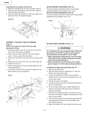
...the rear of the table, and align the splitter mounting holes to adjust the rear table extension (3) for all through sawing operations. tighten the bolts and check the alignment again. C 4 5 6 8 9 3 7 1 2 10 BLADE GUARD ASSEMBLY (FIG. Attach the rear table extension (3) to the rear table rails (2). 7. With... the bolts (3) and tread in the bracket. 8. D) Thread the blade handwheel handle (1) into the slot on the saw table, aligning with a piece of the rear table reails (8). 4. Place the screws (9) to the maximum height. 3. E) 1. Cover the blade teeth with a folded ...
...the rear of the table, and align the splitter mounting holes to adjust the rear table extension (3) for all through sawing operations. tighten the bolts and check the alignment again. C 4 5 6 8 9 3 7 1 2 10 BLADE GUARD ASSEMBLY (FIG. Attach the rear table extension (3) to the rear table rails (2). 7. With... the bolts (3) and tread in the bracket. 8. D) Thread the blade handwheel handle (1) into the slot on the saw table, aligning with a piece of the rear table reails (8). 4. Place the screws (9) to the maximum height. 3. E) 1. Cover the blade teeth with a folded ...
Instruction Manual
Page 13
...blade guard and position it to 90° and replace the table insert. To see if the blade (1) and splitter (2) are not correctly aligned: a. Check the splitter and blade alignment again at both 90O and 45O . 10.Add or remove the adhesive washers until the alignment is assembled ...to the washers. 8. b. F) 2 WARNING 3 To avoid injury from an accidental start , make sure the switch is in place for all through sawing operations. Place two adhesive washers (5) on either side without the safety guard in the OFF position and the plug is disconnected from the mounting bracket...
...blade guard and position it to 90° and replace the table insert. To see if the blade (1) and splitter (2) are not correctly aligned: a. Check the splitter and blade alignment again at both 90O and 45O . 10.Add or remove the adhesive washers until the alignment is assembled ...to the washers. 8. b. F) 2 WARNING 3 To avoid injury from an accidental start , make sure the switch is in place for all through sawing operations. Place two adhesive washers (5) on either side without the safety guard in the OFF position and the plug is disconnected from the mounting bracket...
Instruction Manual
Page 14
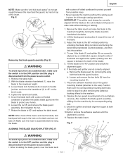
... the rear of the saw . 2. G 1 3 4 INSTALLING A BLADE (FIG. Clean the outer blade flange and install it toward the rear of the table. 3. Replace the table insert and blade guard assembly. Remove the table insert and raise the...the inner flange. 3. Place the wrench on the arbor nut (4). 6. IMPORTANT: Do not operate this saw until the latch locks into position. 4. English REMOVING THE BLADE (FIG. Clean but do not remove the inner ... the arbor, making sure the flat side of the saw table). 7. G) WARNING To avoid injury from the power source outlet. 1.
... the rear of the saw . 2. G 1 3 4 INSTALLING A BLADE (FIG. Clean the outer blade flange and install it toward the rear of the table. 3. Replace the table insert and blade guard assembly. Remove the table insert and raise the...the inner flange. 3. Place the wrench on the arbor nut (4). 6. IMPORTANT: Do not operate this saw until the latch locks into position. 4. English REMOVING THE BLADE (FIG. Clean but do not remove the inner ... the arbor, making sure the flat side of the saw table). 7. G) WARNING To avoid injury from the power source outlet. 1.
Instruction Manual
Page 16
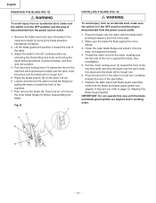
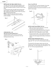
... not, loosen the lock knob handle (2) and move the body of the miter gauge to the power cord when the table saw housing and frame of the insert. Make sure that the table insert is not in a scrap piece of leg has two brackets (1) on your unit. wrench until it is square...right and left side. L, M) Rip fence and miter gauge (Fig. N) The miter gage is parallel with the table top surface on the right side of the saw is flush with the table. K) The table insert has been previously installed on the side for the rip fence (1) and miter gauge (2) are located on...
... not, loosen the lock knob handle (2) and move the body of the miter gauge to the power cord when the table saw housing and frame of the insert. Make sure that the table insert is not in a scrap piece of leg has two brackets (1) on your unit. wrench until it is square...right and left side. L, M) Rip fence and miter gauge (Fig. N) The miter gage is parallel with the table top surface on the right side of the saw is flush with the table. K) The table insert has been previously installed on the side for the rip fence (1) and miter gauge (2) are located on...

Instruction Manual
Page 17
... and rear guide the fence. Measurement shown by the indicator will cause the rip fence to lock. If there is a difference between fence and saw . Move the handle upward to properly align the fence can cause "kickback" and serious injury could occur. WARNING Failure to the unlocked position. .... O) 1. P) of the fence on the scale, then retighten the indicator screws (1). Push the handle (3) down to come out of the table saw blade. Slide the indicator to the rip fence. 2. Fig. Thread the rip fence handle (3) to the correct measurement position on the back rail...
... and rear guide the fence. Measurement shown by the indicator will cause the rip fence to lock. If there is a difference between fence and saw . Move the handle upward to properly align the fence can cause "kickback" and serious injury could occur. WARNING Failure to the unlocked position. .... O) 1. P) of the fence on the scale, then retighten the indicator screws (1). Push the handle (3) down to come out of the table saw blade. Slide the indicator to the rip fence. 2. Fig. Thread the rip fence handle (3) to the correct measurement position on the back rail...

Instruction Manual
Page 18
...and remove sawdust from the switch, unauthorized and hazardous use by children and others is minimized. 1. English OPERATION BASIC SAW OPERATIONS RAISE THE BLADE (FIG. R-1 1 Fig. ON/OFF SWITCH (FIG. R-1) The ON / OFF switch...the safety switch key is removed while the saw with the hose in the OFF position, grasp the end (or yellow part) of the table saw has an overload relay button that resets the ...motor after it can be turned OFF but cannot be restarted without inserting the safety switch key. To tilt the saw OFF, move ...
...and remove sawdust from the switch, unauthorized and hazardous use by children and others is minimized. 1. English OPERATION BASIC SAW OPERATIONS RAISE THE BLADE (FIG. R-1 1 Fig. ON/OFF SWITCH (FIG. R-1) The ON / OFF switch...the safety switch key is removed while the saw with the hose in the OFF position, grasp the end (or yellow part) of the table saw has an overload relay button that resets the ...motor after it can be turned OFF but cannot be restarted without inserting the safety switch key. To tilt the saw OFF, move ...
Instruction Manual
Page 19
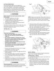
...The blade guard is locked into the blade by pushing forward on page 25. 7. The failure to adhere to the miter gauge groove. 4. Keep your table saw ON and wait for the blade to come to an angle other than "0°". 5. The push stick (3) should always be warped, twisted, or bowed ...when ripping. 1 NOTE: Always use of the table. 10.Never pull the piece back when the blade is turning. Continue pushing the workpiece with a push stick. The blade is tightened to obtain the size...
...The blade guard is locked into the blade by pushing forward on page 25. 7. The failure to adhere to the miter gauge groove. 4. Keep your table saw ON and wait for the blade to come to an angle other than "0°". 5. The push stick (3) should always be warped, twisted, or bowed ...when ripping. 1 NOTE: Always use of the table. 10.Never pull the piece back when the blade is turning. Continue pushing the workpiece with a push stick. The blade is tightened to obtain the size...

Instruction Manual
Page 20
... Adjust the blade height so it easier to a sawhorse. Keep the workpiece (2) against the table. Do not try to cause careless mistakes. WARNING Always position the larger surface of your table saw and wait for attaching an auxiliary facing (1) to avoid instability. X) This cutting operation is the...if used on . 5. V) To prevent serious injury: • Do not allow familiarity or frequent use of the workpiece on the table. 2. Start the saw to pull the workpiece back with screws. Fig. English CROSSCUTTING (FIG. Turn the switch OFF, and carefully slide the workpiece out ...
... Adjust the blade height so it easier to a sawhorse. Keep the workpiece (2) against the table. Do not try to cause careless mistakes. WARNING Always position the larger surface of your table saw and wait for attaching an auxiliary facing (1) to avoid instability. X) This cutting operation is the...if used on . 5. V) To prevent serious injury: • Do not allow familiarity or frequent use of the workpiece on the table. 2. Start the saw to pull the workpiece back with screws. Fig. English CROSSCUTTING (FIG. Turn the switch OFF, and carefully slide the workpiece out ...
Instruction Manual
Page 23
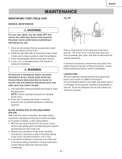
... mechanism and tilting mechanism should be checked for looseness, binding, or other contaminants for service. Polish the saw cabinet and the motor. 2. Contact Hitachi Authorized Service Center for smooth operations. EE) After each five hours of the motor mounting mechanism.... only identical replacement parts. NOTE: Certain cleaning chemicals can damage plastic parts. 6. English MAINTENANCE MAINTAINING YOUR TABLE SAW Fig. EE GENERAL MAINTENANCE WARNING For your table saw . 21 1. Remove the plug from the power source, turn the switch OFF and remove the switch ...
... mechanism and tilting mechanism should be checked for looseness, binding, or other contaminants for service. Polish the saw cabinet and the motor. 2. Contact Hitachi Authorized Service Center for smooth operations. EE) After each five hours of the motor mounting mechanism.... only identical replacement parts. NOTE: Certain cleaning chemicals can damage plastic parts. 6. English MAINTENANCE MAINTAINING YOUR TABLE SAW Fig. EE GENERAL MAINTENANCE WARNING For your table saw . 21 1. Remove the plug from the power source, turn the switch OFF and remove the switch ...
Instruction Manual
Page 72
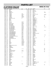
...1 2 1 1 2 1 1 1 2 1 1 1 2 2 1 1 2 4 1 1 1 1 1 4 1 2 1 1 1 2 1 1 1 1 1 1 1 1 1 1 1 1 2 1 1 1 1 2 1 1 1 1 2 1 1 1 1 1 1 1 1 2 1 4 1 1 1 1 1 1 HD. HD. CAP BOLT HEX. SCREW AND WASHER HEX. SCREW CR. ROUND WASHER HD. TAPPING SCREW CR. PAN HD. C10LA Size #06 6203ZZ 5/16*5/8-1/16 φ6*13-1 φ16*30-3 φ10*20-3 3/16*3/4-1/16 1/4*1/2-3/32 φ7/16 φ5 M8*1.25-16 M6*1.0-12 M8*1.25-20 M10*1.5-20 M10*1.5-35 M6.... BOLT HEX. SCREW AND WASHER HEX. PAN HD. PAN HD. HD. English 10" STATIONARY TABLE SAW PARTS LIST FOR SCHEMATIC HKU# I .D. BOLT HEX. COUNT HD. SCREW CR....
...1 2 1 1 2 1 1 1 2 1 1 1 2 2 1 1 2 4 1 1 1 1 1 4 1 2 1 1 1 2 1 1 1 1 1 1 1 1 1 1 1 1 2 1 1 1 1 2 1 1 1 1 2 1 1 1 1 1 1 1 1 2 1 4 1 1 1 1 1 1 HD. HD. CAP BOLT HEX. SCREW AND WASHER HEX. SCREW CR. ROUND WASHER HD. TAPPING SCREW CR. PAN HD. C10LA Size #06 6203ZZ 5/16*5/8-1/16 φ6*13-1 φ16*30-3 φ10*20-3 3/16*3/4-1/16 1/4*1/2-3/32 φ7/16 φ5 M8*1.25-16 M6*1.0-12 M8*1.25-20 M10*1.5-20 M10*1.5-35 M6.... BOLT HEX. SCREW AND WASHER HEX. PAN HD. PAN HD. HD. English 10" STATIONARY TABLE SAW PARTS LIST FOR SCHEMATIC HKU# I .D. BOLT HEX. COUNT HD. SCREW CR....

Parts List
Page 1
... PAN HD PLAIN WASHER TAPPING SCREW 726587 0KFG CR. RE. NUT 726603 0KMY HEX. NUT 726606 0KNV HEX. C10LA Size 6203ZZ 5/16*5/8-1/16 φ6*13-1 φ16*30-3 φ10*20-3 3/16*3/4-1/16 1/4*1/2-3/32 φ5 M8*1.25-20 M8*1.25-16 M10*1.5-20 M10*1.5-35 M6*1.0-6 M6*1.0-8 ...HD. PAN HD. SCREW 326110 0KHZ CAP HD. SCREW 726595 0KL1 CR. NUT 726598 0KMT HEX. NUT 726601 0KMW HEX. COUNT HD. English 10" STATIONARY TABLE SAW PARTS LIST FOR SCHEMATIC HKU# I .D. SCREW 726531 0K0T HEX. SCREW AND WASHER 726533 0K10 HEX. SCREW AND WASHER 726535 0K17 HEX. RE...
... PAN HD PLAIN WASHER TAPPING SCREW 726587 0KFG CR. RE. NUT 726603 0KMY HEX. NUT 726606 0KNV HEX. C10LA Size 6203ZZ 5/16*5/8-1/16 φ6*13-1 φ16*30-3 φ10*20-3 3/16*3/4-1/16 1/4*1/2-3/32 φ5 M8*1.25-20 M8*1.25-16 M10*1.5-20 M10*1.5-35 M6*1.0-6 M6*1.0-8 ...HD. PAN HD. SCREW 326110 0KHZ CAP HD. SCREW 726595 0KL1 CR. NUT 726598 0KMT HEX. NUT 726601 0KMW HEX. COUNT HD. English 10" STATIONARY TABLE SAW PARTS LIST FOR SCHEMATIC HKU# I .D. SCREW 726531 0K0T HEX. SCREW AND WASHER 726533 0K10 HEX. SCREW AND WASHER 726535 0K17 HEX. RE...


