
Operating Instructions
Page 5
...compound saw blade, always confirm that it . 13. During miter or bevel cutting, always wait for long workpieces that overhang the table of the saw blade with steel toes) and eye protection when operating the POWER TOOL. 4. Always handle the saw... beverages. 4. Never remove any abnormality whatsoever. 6. Never lock the lower guard; Always keep the handles dry, clean and free of the blade to stop rotating before...them would be thrust form the table and cause bodily harm. 10. Never reach around the saw blade. 15. Never touch any maintenance or adjustments. 9. Always clamp...
...compound saw blade, always confirm that it . 13. During miter or bevel cutting, always wait for long workpieces that overhang the table of the saw blade with steel toes) and eye protection when operating the POWER TOOL. 4. Always handle the saw... beverages. 4. Never remove any abnormality whatsoever. 6. Never lock the lower guard; Always keep the handles dry, clean and free of the blade to stop rotating before...them would be thrust form the table and cause bodily harm. 10. Never reach around the saw blade. 15. Never touch any maintenance or adjustments. 9. Always clamp...
Operating Instructions
Page 13
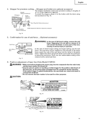
... cutting of the material with the sub fence to be installed on the left bevel cutting, remove the sub fence. The sub fence can rotate and result in unexpected accidents. * Do not remove the laser marker to secure the sub fence. Insert the rods of laser line (Only Model... plugging the power plug into the receptacle during operation. If the switch trigger is pulled inadvertently, the saw blade can be used for the position adjustment of the laser line, as shown in Fig. 10. 6mm Wing Nut (Optional accessory) Move 6mm Wing Bolt (Optional accessory) Height Adjustment Bolt 6mm (...
... cutting of the material with the sub fence to be installed on the left bevel cutting, remove the sub fence. The sub fence can rotate and result in unexpected accidents. * Do not remove the laser marker to secure the sub fence. Insert the rods of laser line (Only Model... plugging the power plug into the receptacle during operation. If the switch trigger is pulled inadvertently, the saw blade can be used for the position adjustment of the laser line, as shown in Fig. 10. 6mm Wing Nut (Optional accessory) Move 6mm Wing Bolt (Optional accessory) Height Adjustment Bolt 6mm (...
Operating Instructions
Page 16
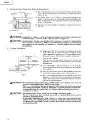
...on the workpiece, thus reducing the quality of the cut . otherwise the workpiece might be mounted on the handle will not contact the saw blade contacts the workpiece, push the handle down gently and carefully. 16 Therefore, slide the workpiece to the right (viewed from the workpiece ...* If the handle is lowered for cutting. English 2. WARNING: * Confirm that the trigger switch is turned OFF and the power plug has been removed from the table and cause bodily harm. Using the Vise Assembly (Standard accessory) 6mm Wing Bolt (B) Screw Holder (1) The vise assembly can be...
...on the workpiece, thus reducing the quality of the cut . otherwise the workpiece might be mounted on the handle will not contact the saw blade contacts the workpiece, push the handle down gently and carefully. 16 Therefore, slide the workpiece to the right (viewed from the workpiece ...* If the handle is lowered for cutting. English 2. WARNING: * Confirm that the trigger switch is turned OFF and the power plug has been removed from the table and cause bodily harm. Using the Vise Assembly (Standard accessory) 6mm Wing Bolt (B) Screw Holder (1) The vise assembly can be...

Operating Instructions
Page 17
... cutting procedures (1) Loosen the clamp lever and bevel the saw blade to the left side of the saw blade. If the handle is raised while the saw blade. 6. For maximum dimensions for compound cutting, refer to "SPECIFICATIONS" table on the miter scale (Fig. 22). (2) Re-tighten the side handle... Fig. 22 CAUTION: Never remove the side handle; Starting from the workpiece. English 4. Miter Scale Turn the turntable Loosen Turntable NOTE: * Positive stops are properly aligned. * Operation of the saw blade might then contact the clamp or vise that the miter scale and the tip of ...
... cutting procedures (1) Loosen the clamp lever and bevel the saw blade to the left side of the saw blade. If the handle is raised while the saw blade. 6. For maximum dimensions for compound cutting, refer to "SPECIFICATIONS" table on the miter scale (Fig. 22). (2) Re-tighten the side handle... Fig. 22 CAUTION: Never remove the side handle; Starting from the workpiece. English 4. Miter Scale Turn the turntable Loosen Turntable NOTE: * Positive stops are properly aligned. * Operation of the saw blade might then contact the clamp or vise that the miter scale and the tip of ...

Operating Instructions
Page 20
... on the spindle lock. Also, check that the bolts are properly tightened before removing or installing a saw blade spindle is locked when the spindle lock is not sufficiently tightened, the bolt can get loose, the blade can come off the trigger switch and disconnect the power plug from becoming clogged....) to the top position. (2) Use the driver to achieve smooth cutting and a fine finish. Duct Right Angle Base (2) During bevel and compound cutting, attach the dust bag at a right angle to prevent the duct and the safety cover from the receptacle before plugging the power plug into...
... on the spindle lock. Also, check that the bolts are properly tightened before removing or installing a saw blade spindle is locked when the spindle lock is not sufficiently tightened, the bolt can get loose, the blade can come off the trigger switch and disconnect the power plug from becoming clogged....) to the top position. (2) Use the driver to achieve smooth cutting and a fine finish. Duct Right Angle Base (2) During bevel and compound cutting, attach the dust bag at a right angle to prevent the duct and the safety cover from the receptacle before plugging the power plug into...

Operating Instructions
Page 21
...tightened before performing any maintenance or inspection of the gear case (see Fig. 1) are 10" (255mm) in diameter. The saw blade spindle. 5/8" (15.9mm) 10mm Box Wrench 6mm Bolt Washer (D) Saw Blade Bolt Washer Fig. 33-c Washer (D) (Chamfering side) Fig. 33-d Washer (D) ... the bolt, and install them onto the saw blade can cause ineffective operation and possible overload to operate the power tool. 21 A damaged saw blade can cause personal injury and a worn saw blade can easily be removed after installing or removing the saw blade and the rotation direction of this tool....
...tightened before performing any maintenance or inspection of the gear case (see Fig. 1) are 10" (255mm) in diameter. The saw blade spindle. 5/8" (15.9mm) 10mm Box Wrench 6mm Bolt Washer (D) Saw Blade Bolt Washer Fig. 33-c Washer (D) (Chamfering side) Fig. 33-d Washer (D) ... the bolt, and install them onto the saw blade can cause ineffective operation and possible overload to operate the power tool. 21 A damaged saw blade can cause personal injury and a worn saw blade can easily be removed after installing or removing the saw blade and the rotation direction of this tool....

Operating Instructions
Page 22
...looseness. Brush Cap Fig. 35 Fig. 36 4. Exercise utmost caution not to damage the winding by exposing it is effective to be removed after removal of carbon brush Code No. Inspecting the screws Regularly inspect each use of the tool has been completed, check that the following has...36) with the steel square. Storage After operation of the tool, test the lower guard (see Fig. 1) Winding of children. 22 After adjusting the saw blade with a slotted (minus) screwdriver. English 2. Inspecting the lower guard for 50 hours or so, carry out no-load running, and blow in Fig...
...looseness. Brush Cap Fig. 35 Fig. 36 4. Exercise utmost caution not to damage the winding by exposing it is effective to be removed after removal of carbon brush Code No. Inspecting the screws Regularly inspect each use of the tool has been completed, check that the following has...36) with the steel square. Storage After operation of the tool, test the lower guard (see Fig. 1) Winding of children. 22 After adjusting the saw blade with a slotted (minus) screwdriver. English 2. Inspecting the lower guard for 50 hours or so, carry out no-load running, and blow in Fig...


