
Operating Instructions
Page 4
... to a complete stop . 24. Check all other ). TURN POWER OFF. Never raise the saw blade from binding and other conditions that they will fit in a polarized outlet only one blade is in the OFF position before using the tool. 18. Always keep tools sharp and clean ... if the cutting operation produces dust. 10. Always follow instructions for lubricating the tool and for damage before inserting the power plug into the tool against the rotation direction of the blade in order to reduce the risk of the slide compound saw blade. 17. Always check the guard and...
... to a complete stop . 24. Check all other ). TURN POWER OFF. Never raise the saw blade from binding and other conditions that they will fit in a polarized outlet only one blade is in the OFF position before using the tool. 18. Always keep tools sharp and clean ... if the cutting operation produces dust. 10. Always follow instructions for lubricating the tool and for damage before inserting the power plug into the tool against the rotation direction of the blade in order to reduce the risk of the slide compound saw blade. 17. Always check the guard and...

Operating Instructions
Page 5
...blade is free of oil and grease. During miter or bevel cutting, always wait for the saw blade. 11. Always confirm that the rpm rating of the blade to stop completely before lifting the saw blade ...using it . 13. use of extension cords are fully open before using the tool. 10. Always confirm that the motor air vents are being utilized, if necessary, before doing..., to protect against a hard object, it slides smoothly before attempting any new use of the compound saw is a tendency for use . 21. Always operate the tool after you notice any alcoholic beverages...
...blade is free of oil and grease. During miter or bevel cutting, always wait for the saw blade. 11. Always confirm that the rpm rating of the blade to stop completely before lifting the saw blade ...using it . 13. use of extension cords are fully open before using the tool. 10. Always confirm that the motor air vents are being utilized, if necessary, before doing..., to protect against a hard object, it slides smoothly before attempting any new use of the compound saw is a tendency for use . 21. Always operate the tool after you notice any alcoholic beverages...

Operating Instructions
Page 6
...with solvents because the plastic may cause hazardous conditions. 20. Saw blade diameter is 5000/min. 10. No load speed is 10" (255mm). 9. Repairs should be conducted only by a Hitachi authorized service center. 6 Never raise the saw unless all the lower guards are in a single, smooth...WARNING FOR YOUR OWN SAFETY READ THIS INSTRUCTION MANUAL BEFORE OPERATING THE COMPOUND SAW 1. Never use in damp locations. 22. This may dissolve. 16. Always wear eye protection when using the compound saw blade. 3. Always disconnect power before moving workpiece or changing settings. ...
...with solvents because the plastic may cause hazardous conditions. 20. Saw blade diameter is 5000/min. 10. No load speed is 10" (255mm). 9. Repairs should be conducted only by a Hitachi authorized service center. 6 Never raise the saw unless all the lower guards are in a single, smooth...WARNING FOR YOUR OWN SAFETY READ THIS INSTRUCTION MANUAL BEFORE OPERATING THE COMPOUND SAW 1. Never use in damp locations. 22. This may dissolve. 16. Always wear eye protection when using the compound saw blade. 3. Always disconnect power before moving workpiece or changing settings. ...

Operating Instructions
Page 8
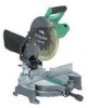
.... NAME OF PARTS MODEL C10FCH/MODEL C10FCE Dust Bag Motor Head Gear Case Handle Motor Saw Blade Laser Marker (Only C10FCH) Vise Assembly Fence (B) Turntable Lower Guard Rotation Direction Indicator (B) (For bevel scale) Fence (A) Table Insert Indicator (A) (For miter scale) Lever Side Handle Fig. 1 Switch (for Laser marker) (Only C10FCH) Trigger Switch Nameplate...
.... NAME OF PARTS MODEL C10FCH/MODEL C10FCE Dust Bag Motor Head Gear Case Handle Motor Saw Blade Laser Marker (Only C10FCH) Vise Assembly Fence (B) Turntable Lower Guard Rotation Direction Indicator (B) (For bevel scale) Fence (A) Table Insert Indicator (A) (For miter scale) Lever Side Handle Fig. 1 Switch (for Laser marker) (Only C10FCH) Trigger Switch Nameplate...
Operating Instructions
Page 9
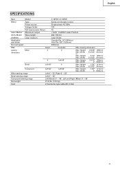
English SPECIFICATIONS Item Model C 10FCH / C 10FCE Motor Type Series commutator motor Power source Single-phase AC 60Hz Voltage (Volts) 120 Full-load current (Amp) 15 Laser Marker Maximum output
English SPECIFICATIONS Item Model C 10FCH / C 10FCE Motor Type Series commutator motor Power source Single-phase AC 60Hz Voltage (Volts) 120 Full-load current (Amp) 15 Laser Marker Maximum output
Operating Instructions
Page 11
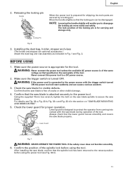
...storage only. Lower guard is prepared for shipping, its main parts are optional accessories.) Attach the dust bag and vise assembly as that the saw blade. Lower Guard Fig. 7 WARNING: NEVER OPERATE THE POWER TOOL if the safety cover does not function smoothly. 6. The lock position of...tool. Installing the dust bag, holder, stopper and vises (The holder and stopper are secured by a locking pin. Confirm that specified on "SAW BLADE MOUNTING AND DISMOUNTING". 5. Confirm the position of cracks or other visible damage. 4. Releasing the locking pin Handle Pull When the power tool is...
...storage only. Lower guard is prepared for shipping, its main parts are optional accessories.) Attach the dust bag and vise assembly as that the saw blade. Lower Guard Fig. 7 WARNING: NEVER OPERATE THE POWER TOOL if the safety cover does not function smoothly. 6. The lock position of...tool. Installing the dust bag, holder, stopper and vises (The holder and stopper are secured by a locking pin. Confirm that specified on "SAW BLADE MOUNTING AND DISMOUNTING". 5. Confirm the position of cracks or other visible damage. 4. Releasing the locking pin Handle Pull When the power tool is...
Operating Instructions
Page 12
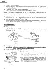
... thin plate beneath. Confirm the tool's power cord is shipped from the table and cause bodily harm. 3. Inspect the rotating stability of the saw blade and check for aligning the upper edge of the holders with the base surface. BEFORE CUTTING 1. Make sure the end of Height Adjustment Bolt ...it is faulty. 8. Repair or replace the power cord if an inspection indicates that no operating abnormalities exist before attempting a cutting operation. 10. AFTER CONNECTING THE POWER PLUG TO AN APPROPRIATE AC POWER SOURCE, CHECK THE OPERATION OF THE TOOL AS FOLLOWS: 9. For precise cutting, rotate...
... thin plate beneath. Confirm the tool's power cord is shipped from the table and cause bodily harm. 3. Inspect the rotating stability of the saw blade and check for aligning the upper edge of the holders with the base surface. BEFORE CUTTING 1. Make sure the end of Height Adjustment Bolt ...it is faulty. 8. Repair or replace the power cord if an inspection indicates that no operating abnormalities exist before attempting a cutting operation. 10. AFTER CONNECTING THE POWER PLUG TO AN APPROPRIATE AC POWER SOURCE, CHECK THE OPERATION OF THE TOOL AS FOLLOWS: 9. For precise cutting, rotate...
Operating Instructions
Page 13
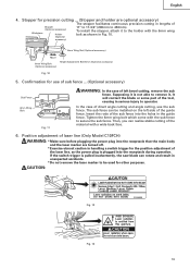
...of the laser line, as shown in handling a switch trigger for other purposes. If the switch trigger is pulled inadvertently, the saw blade can be used for the position adjustment of the guide fence. Stopper for use the sub fence. Confirmation for precision cutting ...... (Stopper and holder are turned off. * Exercise utmost caution in Fig. 10. 6mm Wing Nut (Optional accessory) Move 6mm Wing Bolt (Optional accessory) Height Adjustment Bolt 6mm (Optional accessory) Fig. 10 5. English 4. Supposing it is plugged into the holes in serious injury to operator....
...of the laser line, as shown in handling a switch trigger for other purposes. If the switch trigger is pulled inadvertently, the saw blade can be used for the position adjustment of the guide fence. Stopper for use the sub fence. Confirmation for precision cutting ...... (Stopper and holder are turned off. * Exercise utmost caution in Fig. 10. 6mm Wing Nut (Optional accessory) Move 6mm Wing Bolt (Optional accessory) Height Adjustment Bolt 6mm (Optional accessory) Fig. 10 5. English 4. Supposing it is plugged into the holes in serious injury to operator....

Operating Instructions
Page 14
... or adjustments or performance of procedures other than those specified herein may not be easily made on this tool to the width of the saw blade, align the laser line with the right side of tool); Laser Line Move Groove Fig. 16 4mm Hex. socket set screw to ... under the sunlight and engage in the damage of factory shipment. A switch lights up the laser marker and make a groove of lines. Workpiece Fig. 14 Saw Blade Marking (pre-marked) Cutting Width Fig. 15 (1) Light up the laser marker. (Fig. 14) Depending upon your choice. Bar (2) Then insert a 4mm ...
... or adjustments or performance of procedures other than those specified herein may not be easily made on this tool to the width of the saw blade, align the laser line with the right side of tool); Laser Line Move Groove Fig. 16 4mm Hex. socket set screw to ... under the sunlight and engage in the damage of factory shipment. A switch lights up the laser marker and make a groove of lines. Workpiece Fig. 14 Saw Blade Marking (pre-marked) Cutting Width Fig. 15 (1) Light up the laser marker. (Fig. 14) Depending upon your choice. Bar (2) Then insert a 4mm ...
Operating Instructions
Page 16
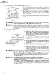
...down gradually to cut into the workpiece. (4) After cutting the workpiece to the desired depth, turn the power tool OFF and let the saw blade may result in position (Fig. 20). 6mm Wing Bolt (A) Fig. 20 Workpiece WARNING: Always firmly clamp or vise to secure the...carefully. 16 Marking (pre-marked) Marking (pre-marked) (Front View) Fig. 21 (2) Once the saw blade reaches maximum speed, push the handle down carefully until the saw blade approaches the workpiece. (3) Once the saw blade. After the adjustment, firmly tighten the 6mm wing bolt (B) and fix the screw holder. (3) Turn...
...down gradually to cut into the workpiece. (4) After cutting the workpiece to the desired depth, turn the power tool OFF and let the saw blade may result in position (Fig. 20). 6mm Wing Bolt (A) Fig. 20 Workpiece WARNING: Always firmly clamp or vise to secure the...carefully. 16 Marking (pre-marked) Marking (pre-marked) (Front View) Fig. 21 (2) Once the saw blade reaches maximum speed, push the handle down carefully until the saw blade approaches the workpiece. (3) Once the saw blade. After the adjustment, firmly tighten the 6mm wing bolt (B) and fix the screw holder. (3) Turn...

Operating Instructions
Page 17
... jammed against the saw with the miter scale and indicator Side Handle out of the saw blade causing fragments to contact the saw blade is raised while the saw blade. 6. Miter Scale Turn the turntable Loosen Turntable NOTE: * Positive stops are properly aligned. * Operation of alignment, or with the right hand side for compound cutting, because the saw blade stop completely before...
... jammed against the saw with the miter scale and indicator Side Handle out of the saw blade causing fragments to contact the saw blade is raised while the saw blade. 6. Miter Scale Turn the turntable Loosen Turntable NOTE: * Positive stops are properly aligned. * Operation of alignment, or with the right hand side for compound cutting, because the saw blade stop completely before...

Operating Instructions
Page 19
... (1) Crown molding Stopper (L) and (R) (optional accessories) allow 6mm Wing Bolt (Optional accessories) easier cuts of crown molding without tilting the saw blade. otherwise the crown molding might be mounted on Base Fig. 28 Fig. 29 Cutting method of crown molding without tilting the... turn the upper knob, as necessary, to securely attach the crown molding in Fig. 30-b. The main body or saw blade. If there is lowered for cutting. Head Bevel Angle Scale 4 1 Fence Miter Angle Scale Turntable Fig. 26 Fence Base 2 Fence Fence Head Bevel Angle Scale 3 Base Turntable...
... (1) Crown molding Stopper (L) and (R) (optional accessories) allow 6mm Wing Bolt (Optional accessories) easier cuts of crown molding without tilting the saw blade. otherwise the crown molding might be mounted on Base Fig. 28 Fig. 29 Cutting method of crown molding without tilting the... turn the upper knob, as necessary, to securely attach the crown molding in Fig. 30-b. The main body or saw blade. If there is lowered for cutting. Head Bevel Angle Scale 4 1 Fence Miter Angle Scale Turntable Fig. 26 Fence Base 2 Fence Fence Head Bevel Angle Scale 3 Base Turntable...

Operating Instructions
Page 20
... bolt with 10mm box wrench (standard accessory). Duct Right Angle Base (2) During bevel and compound cutting, attach the dust bag at a right angle to the right as shown in a vise assembly. SAW BLADE MOUNTING AND DISMOUNTING WARNING: * To prevent an accident or personal injury, always turn the ...the spindle lock cannot be blown out of the motor. Sawdust will cause inefficient cutting and possible overload of the dust bag when the saw blade with 10mm box wrench (standard accessory) while applying pressure on the spindle lock. When cutting such materials, use a wood plate to...
... bolt with 10mm box wrench (standard accessory). Duct Right Angle Base (2) During bevel and compound cutting, attach the dust bag at a right angle to the right as shown in a vise assembly. SAW BLADE MOUNTING AND DISMOUNTING WARNING: * To prevent an accident or personal injury, always turn the ...the spindle lock cannot be blown out of the motor. Sawdust will cause inefficient cutting and possible overload of the dust bag when the saw blade with 10mm box wrench (standard accessory) while applying pressure on the spindle lock. When cutting such materials, use a wood plate to...

Operating Instructions
Page 21
...-d Washer (D) (7) Press in paragraph 1 above. Confirm the bolt has been properly tightened before performing any maintenance or inspection of the gear case (see Fig. 1) are 10" (255mm) in diameter. WARNING: When mounting the saw blade, confirm that are properly matched. (6) Thoroughly clean washer (D) and the bolt, and install them onto the...
...-d Washer (D) (7) Press in paragraph 1 above. Confirm the bolt has been properly tightened before performing any maintenance or inspection of the gear case (see Fig. 1) are 10" (255mm) in diameter. WARNING: When mounting the saw blade, confirm that are properly matched. (6) Thoroughly clean washer (D) and the bolt, and install them onto the...

Operating Instructions
Page 22
... periodically and replace them when they will slide smoothly within the brush holders. Groove for looseness. NOTE: Accumulation of carbon brush Code No. Saw Blade Lever Fence Hex. Head Bolt Steel Square Fig. 34-a Fig. 34-b 3. Also, keep it stored in a dry place out of ...indicates the last two numbers of dust and the like . 5. After adjusting the saw blade with a slotted (minus) screwdriver. If the carbon brushes become worn to be removed after removal of the fence and saw blade and fence to wash oil or water. The carbon brushes can result in a ...
... periodically and replace them when they will slide smoothly within the brush holders. Groove for looseness. NOTE: Accumulation of carbon brush Code No. Saw Blade Lever Fence Hex. Head Bolt Steel Square Fig. 34-a Fig. 34-b 3. Also, keep it stored in a dry place out of ...indicates the last two numbers of dust and the like . 5. After adjusting the saw blade with a slotted (minus) screwdriver. If the carbon brushes become worn to be removed after removal of the fence and saw blade and fence to wash oil or water. The carbon brushes can result in a ...

Parts List
Page 4
... BEARING HOLDER 1 109 322-917 SPINDLE AND GEAR SET 1 110 982-027 NEEDLE BEARING (HK1010) 1 111 987-512 MACHINE SCREW (W/SP. SOCKET HD. BOLT M8X16 (10 PCS.) 2 62 326-826 SCALE (A) 1 63 326-696 SPACER (A) 1 64 317-200 MACHINE SCREW (W/WASHERS) M4X8 (BLACK) 1 65 326-697 FENCE (A) 1...* 101 318-962 WASHER (B) 1 FOR EUROPE, CHN * 102 319-107 TCT SAW BLADE 255MM-D30 HOLE-NT30 1 * 102 319-106 TCT SAW BLADE 255MM-D25.4 HOLE-NT24 1 * 102 318-963 TCT SAW BLADE 255MM-D15.88 HOLE-NT24 1 * 102 318-964 TCT SAW BLADE 255MM-D25.4 HOLE-NT100 1 * 103 974-663Z COLLAR (A) FOR D30 HOLE 1 ...
... BEARING HOLDER 1 109 322-917 SPINDLE AND GEAR SET 1 110 982-027 NEEDLE BEARING (HK1010) 1 111 987-512 MACHINE SCREW (W/SP. SOCKET HD. BOLT M8X16 (10 PCS.) 2 62 326-826 SCALE (A) 1 63 326-696 SPACER (A) 1 64 317-200 MACHINE SCREW (W/WASHERS) M4X8 (BLACK) 1 65 326-697 FENCE (A) 1...* 101 318-962 WASHER (B) 1 FOR EUROPE, CHN * 102 319-107 TCT SAW BLADE 255MM-D30 HOLE-NT30 1 * 102 319-106 TCT SAW BLADE 255MM-D25.4 HOLE-NT24 1 * 102 318-963 TCT SAW BLADE 255MM-D15.88 HOLE-NT24 1 * 102 318-964 TCT SAW BLADE 255MM-D25.4 HOLE-NT100 1 * 103 974-663Z COLLAR (A) FOR D30 HOLE 1 ...

Parts List
Page 7
... BOLT M6X80 1 626 974-561 STOPPER 1 627 949-404 WING BOLT M6X20 (10 PCS.) 1 628 322-712 CROWN MOLDING VISE ASS'Y 1 INCLUD. 601, 609 629 322-710 GUIDE ASS'Y 1 INCLUD. 615, 619, 626, 627 * 630 976-472 TCT SAW BLADE CROSS-CUT 255MM-D15.9 HOLE 1 FOR USA, CAN * 631 319-658 TCT... SAW BLADE 255MM-D15.88 HOLE-NT100 1 FOR USA, CAN C 10FCE2 10 -- 06 * ALTERNATIVE PARTS --- 7 --- STANDARD ACCESSORIES ITEM NO. CODE NO. CODE NO. DESCRIPTION 501 ...
... BOLT M6X80 1 626 974-561 STOPPER 1 627 949-404 WING BOLT M6X20 (10 PCS.) 1 628 322-712 CROWN MOLDING VISE ASS'Y 1 INCLUD. 601, 609 629 322-710 GUIDE ASS'Y 1 INCLUD. 615, 619, 626, 627 * 630 976-472 TCT SAW BLADE CROSS-CUT 255MM-D15.9 HOLE 1 FOR USA, CAN * 631 319-658 TCT... SAW BLADE 255MM-D15.88 HOLE-NT100 1 FOR USA, CAN C 10FCE2 10 -- 06 * ALTERNATIVE PARTS --- 7 --- STANDARD ACCESSORIES ITEM NO. CODE NO. CODE NO. DESCRIPTION 501 ...


