Safety and Regulatory Information Desktops, Thin Clients, and Personal Workstations
Page 28
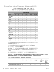
... 2-2 Toxic and Hazardous Substances and Elements Part Name Lead (Pb) Mercury (Hg) Cadmium (Cd) Hexavalent Chromium (Cr(VI)) Polybrominated biphenyls (PBB) Polybrominated diphenyl ethers (PBDE) Motherboard, processor and heat sink X O O O O O 22 Chapter 2 Regulatory Agency Notices ENWW
... 2-2 Toxic and Hazardous Substances and Elements Part Name Lead (Pb) Mercury (Hg) Cadmium (Cd) Hexavalent Chromium (Cr(VI)) Polybrominated biphenyls (PBB) Polybrominated diphenyl ethers (PBDE) Motherboard, processor and heat sink X O O O O O 22 Chapter 2 Regulatory Agency Notices ENWW

Upgrading and Servicing Guide
Page 20
Touching the gold contacts may damage the module. WARNING: Handle the memory module with care. Be careful to http://www.hp.com/support in your Web browser. 2 Select your country/region and language. 3 From the Support and Drivers page, click See support and ...DIMMs (double data rate dual in-line memory modules). Avoid touching the memory chips. 16 Upgrading and Servicing Guide Removing and Replacing Memory The motherboard contains one or two memory module sockets for specific memory module information and specifications: 1 Go to not touch any memory module contacts. Memory ...
Touching the gold contacts may damage the module. WARNING: Handle the memory module with care. Be careful to http://www.hp.com/support in your Web browser. 2 Select your country/region and language. 3 From the Support and Drivers page, click See support and ...DIMMs (double data rate dual in-line memory modules). Avoid touching the memory chips. 16 Upgrading and Servicing Guide Removing and Replacing Memory The motherboard contains one or two memory module sockets for specific memory module information and specifications: 1 Go to not touch any memory module contacts. Memory ...
Upgrading and Servicing Guide
Page 21
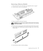
Upgrading and Servicing Guide 17 WARNING: Do not pull the memory module out of the socket. Hold the memory module by its edges only, as you lift it away from the socket. 5 Store the memory module in antistatic packaging. Use the retaining clips to eject the module. 4 Push down the two retaining clips on the motherboard. 3 Move any cabling out of the way, if necessary. See "Removing an Optical Disc Drive" on page 9. 2 Locate the memory socket on the ends of the socket until the memory module pops out of the socket. Removing a Memory Module 1 Remove the optical disc drive.
Upgrading and Servicing Guide 17 WARNING: Do not pull the memory module out of the socket. Hold the memory module by its edges only, as you lift it away from the socket. 5 Store the memory module in antistatic packaging. Use the retaining clips to eject the module. 4 Push down the two retaining clips on the motherboard. 3 Move any cabling out of the way, if necessary. See "Removing an Optical Disc Drive" on page 9. 2 Locate the memory socket on the ends of the socket until the memory module pops out of the socket. Removing a Memory Module 1 Remove the optical disc drive.
Upgrading and Servicing Guide
Page 24
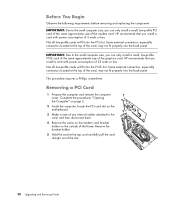
... out of the frame. IMPORTANT: Due to the card, and then disconnect them. 4 Remove the screw on the modem card bracket holder on the motherboard. 3 Make a note of any internal cables attached to the small computer size, you can only install a small, low-profile PCI card of the... Not all low-profile cards will fit into the back panel. Removing a PCI Card 1 Prepare the computer and remove the computer cover. HP recommends that you install a card with power consumption of 25 watts or less. HP recommends that you install a card with power consumption of 5 watts or less.
... out of the frame. IMPORTANT: Due to the card, and then disconnect them. 4 Remove the screw on the modem card bracket holder on the motherboard. 3 Make a note of any internal cables attached to the small computer size, you can only install a small, low-profile PCI card of the... Not all low-profile cards will fit into the back panel. Removing a PCI Card 1 Prepare the computer and remove the computer cover. HP recommends that you install a card with power consumption of 25 watts or less. HP recommends that you install a card with power consumption of 5 watts or less.
Upgrading and Servicing Guide
Page 26
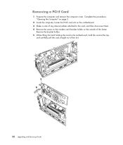
Removing a PCI-E Card 1 Prepare the computer and remove the computer cover. Complete the procedures "Opening the Computer" on page 2. 2 Inside the computer, locate the PCI-E card slot on the outside of the slot. 22 Upgrading and Servicing Guide Remove the bracket holder. 5 While lifting the latch holding the card to the card, and then disconnect them. 4 Remove the screw on the modem card bracket holder on the motherboard. 3 Make a note of any internal cables attached to the motherboard, hold the card at the top, and carefully pull the card straight out of the frame.
Removing a PCI-E Card 1 Prepare the computer and remove the computer cover. Complete the procedures "Opening the Computer" on page 2. 2 Inside the computer, locate the PCI-E card slot on the outside of the slot. 22 Upgrading and Servicing Guide Remove the bracket holder. 5 While lifting the latch holding the card to the card, and then disconnect them. 4 Remove the screw on the modem card bracket holder on the motherboard. 3 Make a note of any internal cables attached to the motherboard, hold the card at the top, and carefully pull the card straight out of the frame.

Upgrading and Servicing Guide
Page 28
.... Complete the procedures "Opening the Computer" on page 2. 2 Gently lay the computer on its side. 3 Complete the procedure "Removing an Optical Disc Drive" on the motherboard provides backup power for the computer's timekeeping capability. If the battery fails, replace it with the same, or equivalent, type of explosion if the battery...
.... Complete the procedures "Opening the Computer" on page 2. 2 Gently lay the computer on its side. 3 Complete the procedure "Removing an Optical Disc Drive" on the motherboard provides backup power for the computer's timekeeping capability. If the battery fails, replace it with the same, or equivalent, type of explosion if the battery...
Start Here Guide
Page 10
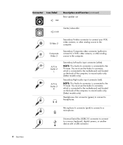
..., keyboard, digital camera, or another device with a USB connector. 4 Start Here You must use the Audio In connector, which is connected to the motherboard and located on the back of the computer, to headphones. A/V In Audio 2 L A/V In Audio 2 R Secondary Left audio input connector (white).... You must use the Audio In connector, which is connected to the motherboard and located on the back of the computer, to record audio only. (Select models only.) Headphones Out connector (green) to connect to record audio...
..., keyboard, digital camera, or another device with a USB connector. 4 Start Here You must use the Audio In connector, which is connected to the motherboard and located on the back of the computer, to headphones. A/V In Audio 2 L A/V In Audio 2 R Secondary Left audio input connector (white).... You must use the Audio In connector, which is connected to the motherboard and located on the back of the computer, to record audio only. (Select models only.) Headphones Out connector (green) to connect to record audio...
Start Here Guide
Page 12
...) to a microphone. Center Rear Audio Line In (blue) connector to connect to connect from set-top box connector (white). Line Side (gray) connector to the motherboard. Some computers include this Audio In connector, which is connected to connect side speakers Side in a multichannel audio configuration. Connector Icon/label Description and function...
...) to a microphone. Center Rear Audio Line In (blue) connector to connect to connect from set-top box connector (white). Line Side (gray) connector to the motherboard. Some computers include this Audio In connector, which is connected to connect side speakers Side in a multichannel audio configuration. Connector Icon/label Description and function...

Start Here Guide
Page 13
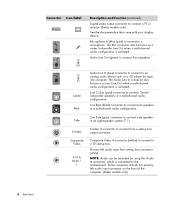
... using this primary right audio input connector on the TV tuner card. Analog Video Out: S-video or composite video (select models only) connects to the motherboard. Digital Out (orange) connects to improve your telephone line wall jack connector. Connector Icon/label A/V In Audio 1 R TV/Cable Ant FM Ant Analog Video Description...
... using this primary right audio input connector on the TV tuner card. Analog Video Out: S-video or composite video (select models only) connects to the motherboard. Digital Out (orange) connects to improve your telephone line wall jack connector. Connector Icon/label A/V In Audio 1 R TV/Cable Ant FM Ant Analog Video Description...

Getting Started Guide
Page 14
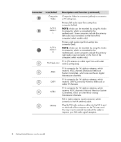
... the computer. NOTE: This Audio In connector is connected to headphones. You must use the Audio In connector, which is connected to the motherboard and located on the back of the computer, to record audio only. (Select models only.) Headphones Out connector (green) to connect to ...the TV tuner. You must use the Audio In connector, which is connected to the motherboard and located on the back of the computer, to the TV tuner. Universal Serial Bus (USB) 2.0 connector to connect to a microphone. NOTE:...
... the computer. NOTE: This Audio In connector is connected to headphones. You must use the Audio In connector, which is connected to the motherboard and located on the back of the computer, to record audio only. (Select models only.) Headphones Out connector (green) to connect to ...the TV tuner. You must use the Audio In connector, which is connected to the motherboard and located on the back of the computer, to the TV tuner. Universal Serial Bus (USB) 2.0 connector to connect to a microphone. NOTE:...

Getting Started Guide
Page 16
... is activated. Primary left audio input connector on the front of the computer. (Select models only.) 6 Getting Started Side Line Side (gray) connector to the motherboard. Line C/Sub (gold) connector to an analog audio device such as a CD player for input into computer. Center Rear Audio Line In (blue) connector to...
... is activated. Primary left audio input connector on the front of the computer. (Select models only.) 6 Getting Started Side Line Side (gray) connector to the motherboard. Line C/Sub (gold) connector to an analog audio device such as a CD player for input into computer. Center Rear Audio Line In (blue) connector to...
Getting Started Guide
Page 17
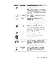
.../amplifier) or digital speakers (select models only). Modem (Line In RJ-11) (select models only). Digital Audio Out Digital audio input (white) connects to the motherboard. VGA Monitor/VGA (blue) display output connector connects to your FM radio signal reception. Some computers include this Audio In connector which is connected to...
.../amplifier) or digital speakers (select models only). Modem (Line In RJ-11) (select models only). Digital Audio Out Digital audio input (white) connects to the motherboard. VGA Monitor/VGA (blue) display output connector connects to your FM radio signal reception. Some computers include this Audio In connector which is connected to...

Getting Started Guide
Page 14
... camera, or another device with a USB connector. Mouse connector to a microphone. You must use the Audio In connector, which is connected to the motherboard and located on the back of the computer, to record audio only (select models only). You must use the Audio In connector, which is connected... to the motherboard and located on the back of the computer, to record audio only (select models only). Power connector. NOTE: This Audio In connector is ...
... camera, or another device with a USB connector. Mouse connector to a microphone. You must use the Audio In connector, which is connected to the motherboard and located on the back of the computer, to record audio only (select models only). You must use the Audio In connector, which is connected... to the motherboard and located on the back of the computer, to record audio only (select models only). Power connector. NOTE: This Audio In connector is ...
Getting Started Guide
Page 16
... channels. NOTE: Audio can be recorded by using this Audio In connector, which is connected to the motherboard. NOTE: Audio can be recorded by using this Audio In connector, which is connected to the motherboard. Some computers include this primary right audio input connector on the front of the cable to improve...
... channels. NOTE: Audio can be recorded by using this Audio In connector, which is connected to the motherboard. NOTE: Audio can be recorded by using this Audio In connector, which is connected to the motherboard. Some computers include this primary right audio input connector on the front of the cable to improve...

