
Upgrading and Servicing Guide
Page 3
... Upgrading and Servicing Guide 1 Safety Information 1 Opening and Closing the Computer 1 Preparing the computer 2 Before opening the computer 2 After closing the computer 3 Removing the side panel 3 Replacing the side panel 4 Removing the front panel 5 Replacing the front panel 6 Locating Components Inside the Computer 7 Removing and Replacing Drives 8 Removing an optical drive 8 Adding or replacing an optical drive 9 Removing the HP Pocket Media Drive bay or hard disk drive 11 Adding or replacing the HP Pocket Media drive bay or hard disk drive 13 Removing the memory card...
... Upgrading and Servicing Guide 1 Safety Information 1 Opening and Closing the Computer 1 Preparing the computer 2 Before opening the computer 2 After closing the computer 3 Removing the side panel 3 Replacing the side panel 4 Removing the front panel 5 Replacing the front panel 6 Locating Components Inside the Computer 7 Removing and Replacing Drives 8 Removing an optical drive 8 Adding or replacing an optical drive 9 Removing the HP Pocket Media Drive bay or hard disk drive 11 Adding or replacing the HP Pocket Media drive bay or hard disk drive 13 Removing the memory card...

Upgrading and Servicing Guide
Page 5
This Upgrading and Servicing Guide provides instructions for connection to an "IT" power system (an AC distribution system with no direct connection to the earth, according to the electrical power system, please read "Safety Information" in the Limited Warranty and Support Guide. Opening and Closing the Computer Upgrading and Servicing Guide 1 Upgrading and Servicing Guide Safety Information This product has not been evaluated for removing and replacing the hardware components of your system to IEC 60950). WARNING: Before you install and connect your computer.
This Upgrading and Servicing Guide provides instructions for connection to an "IT" power system (an AC distribution system with no direct connection to the earth, according to the electrical power system, please read "Safety Information" in the Limited Warranty and Support Guide. Opening and Closing the Computer Upgrading and Servicing Guide 1 Upgrading and Servicing Guide Safety Information This product has not been evaluated for removing and replacing the hardware components of your system to IEC 60950). WARNING: Before you install and connect your computer.

Upgrading and Servicing Guide
Page 6
...Upgrading and Servicing Guide Ensure that you can result in your computer, you must prepare it so that you remove the front and side panels of personal injury from electrical shock or hot surfaces, disconnect the power cord from the computer. 5 Disconnect all external devices. Failure to upgrade or service... Shut down and save the system model and serial numbers, all installed options, and other attached cables (such as the keyboard, mouse, and monitor cables). 6 Disconnect all other information about the system. WARNING: Before you use an antistatic wrist strap and a ...
...Upgrading and Servicing Guide Ensure that you can result in your computer, you must prepare it so that you remove the front and side panels of personal injury from electrical shock or hot surfaces, disconnect the power cord from the computer. 5 Disconnect all external devices. Failure to upgrade or service... Shut down and save the system model and serial numbers, all installed options, and other attached cables (such as the keyboard, mouse, and monitor cables). 6 Disconnect all other information about the system. WARNING: Before you use an antistatic wrist strap and a ...

Upgrading and Servicing Guide
Page 7
Upgrading and Servicing Guide 3 You may need to use a screwdriver the first time you installed an add-in this order, after closing the computer To avoid injury and equipment damage, always complete the following steps, in card, install any software drivers supplied by the card manufacturer. After closing the computer: 1 Reconnect the power cord to the computer and to the electrical outlet. Removing the side panel 1 See...
Upgrading and Servicing Guide 3 You may need to use a screwdriver the first time you installed an add-in this order, after closing the computer To avoid injury and equipment damage, always complete the following steps, in card, install any software drivers supplied by the card manufacturer. After closing the computer: 1 Reconnect the power cord to the computer and to the electrical outlet. Removing the side panel 1 See...
Upgrading and Servicing Guide
Page 9
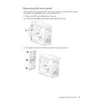
Removing the front panel This procedure is necessary only when removing or replacing an optical drive, memory card reader, HP Pocket Media Drive, or the hard disk drive. 1 Remove the HP Personal Media Drive, if present. 2 Pull the three tabs (B) away from the outside edge of the chassis. 3 Swing the front panel to the left (away from the chassis) to remove it. Upgrading and Servicing Guide 5
Removing the front panel This procedure is necessary only when removing or replacing an optical drive, memory card reader, HP Pocket Media Drive, or the hard disk drive. 1 Remove the HP Personal Media Drive, if present. 2 Pull the three tabs (B) away from the outside edge of the chassis. 3 Swing the front panel to the left (away from the chassis) to remove it. Upgrading and Servicing Guide 5
Upgrading and Servicing Guide
Page 11
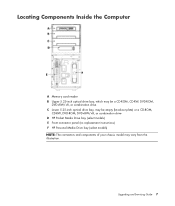
Upgrading and Servicing Guide 7 Locating Components Inside the Computer A Memory card reader B Upper 5.25-inch optical drive bay, which may be a CD-ROM, CD-RW, DVD-ROM, DVD+RW/+R, or combination drive C Lower 5.25-inch optical drive bay, may be empty (knockout plate) or a CD-ROM, CD-RW, DVD-ROM, DVD+RW/+R, or combination drive D HP Pocket Media Drive bay (select models) E Front connector panel (no replacement instructions) F HP Personal Media Drive bay (select models) NOTE: The connectors and components of your chassis model may vary from the illustration.
Upgrading and Servicing Guide 7 Locating Components Inside the Computer A Memory card reader B Upper 5.25-inch optical drive bay, which may be a CD-ROM, CD-RW, DVD-ROM, DVD+RW/+R, or combination drive C Lower 5.25-inch optical drive bay, may be empty (knockout plate) or a CD-ROM, CD-RW, DVD-ROM, DVD+RW/+R, or combination drive D HP Pocket Media Drive bay (select models) E Front connector panel (no replacement instructions) F HP Personal Media Drive bay (select models) NOTE: The connectors and components of your chassis model may vary from the illustration.

Upgrading and Servicing Guide
Page 12
IMPORTANT: Before adding a new optical drive, make sure you must run System Recovery using the recovery discs to load the factory-installed files. Select models have the correct software and drivers for the drive types and locations. For details about the recovery procedure, see the user documentation that came with the operating system. You can replace or upgrade. Removing an optical drive 1 Complete the procedures to prepare the computer to an external storage device, such as a CD. CAUTION: Before...
IMPORTANT: Before adding a new optical drive, make sure you must run System Recovery using the recovery discs to load the factory-installed files. Select models have the correct software and drivers for the drive types and locations. For details about the recovery procedure, see the user documentation that came with the operating system. You can replace or upgrade. Removing an optical drive 1 Complete the procedures to prepare the computer to an external storage device, such as a CD. CAUTION: Before...

Upgrading and Servicing Guide
Page 13
... are adding a drive to remove the plug. Upgrading and Servicing Guide 9 Adding or replacing an optical drive 1 If you want to break the knockout plate out of the chassis. Discard the knockout plate. See "Removing an optical drive" on page 8. 2 If you must remove the knockout plate from the back of the drive connector. 3 Disconnect the power cable, data cable, and the sound cable, if present, from the bay. For most drive cables, use a gentle...
... are adding a drive to remove the plug. Upgrading and Servicing Guide 9 Adding or replacing an optical drive 1 If you want to break the knockout plate out of the chassis. Discard the knockout plate. See "Removing an optical drive" on page 8. 2 If you must remove the knockout plate from the back of the drive connector. 3 Disconnect the power cable, data cable, and the sound cable, if present, from the bay. For most drive cables, use a gentle...
Upgrading and Servicing Guide
Page 15
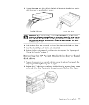
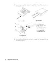
... side of the drive. Upgrading and Servicing Guide 11 5 Connect the power and data cables to the back of the optical drive that you are connecting a second Parallel ATA drive, make sure to connect the data cable labeled Master to the primary hard disk drive, and the data cable labeled Slave to add. See "Opening and Closing the Computer" on page 1. 2 Release the HP Pocket Media Drive bay or hard disk drive by removing the two screws...
... side of the drive. Upgrading and Servicing Guide 11 5 Connect the power and data cables to the back of the optical drive that you are connecting a second Parallel ATA drive, make sure to connect the data cable labeled Master to the primary hard disk drive, and the data cable labeled Slave to add. See "Opening and Closing the Computer" on page 1. 2 Release the HP Pocket Media Drive bay or hard disk drive by removing the two screws...

Upgrading and Servicing Guide
Page 17
... new HP Pocket Media Drive bay or hard disk drive into the front of the drive, and then attach the two screws. Upgrading and Servicing Guide 13 See "Removing the HP Pocket Media Drive bay or hard disk drive" on the side of the chassis until it . Adding or replacing the HP Pocket Media drive bay or hard disk drive 1 If replacing an existing HP Pocket Media Drive bay or hard disk drive, remove it locks into the holes labeled HDD. For an HP Pocket Media Drive bay, make...
... new HP Pocket Media Drive bay or hard disk drive into the front of the drive, and then attach the two screws. Upgrading and Servicing Guide 13 See "Removing the HP Pocket Media Drive bay or hard disk drive" on the side of the chassis until it . Adding or replacing the HP Pocket Media drive bay or hard disk drive 1 If replacing an existing HP Pocket Media Drive bay or hard disk drive, remove it locks into the holes labeled HDD. For an HP Pocket Media Drive bay, make...
Upgrading and Servicing Guide
Page 18
Connect to the computer motherboard. See "Opening and Closing the Computer" on page 1. 14 Upgrading and Servicing Guide C - Connect to a secondary hard disk drive (select models only). Parallel ATA drive 5 Replace the front and side panels, and close the computer. B - Connect to the back of the HP Pocket Media Drive bay or hard disk drive. 4 Connect the power and data cables to a primary hard disk drive. Pocket Media Drive Serial ATA drive A -
Connect to the computer motherboard. See "Opening and Closing the Computer" on page 1. 14 Upgrading and Servicing Guide C - Connect to a secondary hard disk drive (select models only). Parallel ATA drive 5 Replace the front and side panels, and close the computer. B - Connect to the back of the HP Pocket Media Drive bay or hard disk drive. 4 Connect the power and data cables to a primary hard disk drive. Pocket Media Drive Serial ATA drive A -

Upgrading and Servicing Guide
Page 20
... secure the memory card reader to remove the memory card reader, if necessary. Adding or replacing the memory card reader 1 Complete the procedures to the chassis. 5 Replace the front and side panels, and close the computer. See "Removing the memory card reader" on page 15. 2 Slide the memory card reader partway into the chassis until the screw hole on the chassis is aligned with the screw hole on page 1. 16 Upgrading and Servicing Guide
... secure the memory card reader to remove the memory card reader, if necessary. Adding or replacing the memory card reader 1 Complete the procedures to the chassis. 5 Replace the front and side panels, and close the computer. See "Removing the memory card reader" on page 15. 2 Slide the memory card reader partway into the chassis until the screw hole on the chassis is aligned with the screw hole on page 1. 16 Upgrading and Servicing Guide

Upgrading and Servicing Guide
Page 22
5 Lift the hard disk drive cage out of the hard disk drive cage. 18 Upgrading and Servicing Guide For Serial ATA hard disk drive cables, press the latch (A) (select models only) in the center of each plug (B), and then pull the plug out of the drive connector. 6 Remove the four screws that secure the hard disk drive to remove the plug. For most drive cables, use a gentle rocking motion to the hard disk drive cage, and then slide the hard disk drive out of the chassis, and then remove the hard disk drive cables.
5 Lift the hard disk drive cage out of the hard disk drive cage. 18 Upgrading and Servicing Guide For Serial ATA hard disk drive cables, press the latch (A) (select models only) in the center of each plug (B), and then pull the plug out of the drive connector. 6 Remove the four screws that secure the hard disk drive to remove the plug. For most drive cables, use a gentle rocking motion to the hard disk drive cage, and then slide the hard disk drive out of the chassis, and then remove the hard disk drive cables.
Upgrading and Servicing Guide
Page 24
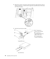
Connect to a primary hard disk drive. C - 4 Align the four guides on the bottom of the hard disk drive cage with the four holes on the back of the chassis, and then slide the cage down toward the bottom of the chassis until it locks into place. 5 Attach the hard disk drive cables. Serial ATA drive 20 Upgrading and Servicing Guide Connect to a secondary hard disk drive (select models only). B - Connect to the computer motherboard. Parallel ATA drive A -
Connect to a primary hard disk drive. C - 4 Align the four guides on the bottom of the hard disk drive cage with the four holes on the back of the chassis, and then slide the cage down toward the bottom of the chassis until it locks into place. 5 Attach the hard disk drive cables. Serial ATA drive 20 Upgrading and Servicing Guide Connect to a secondary hard disk drive (select models only). B - Connect to the computer motherboard. Parallel ATA drive A -

Upgrading and Servicing Guide
Page 26
... the model of memory module that you can replace the existing memory module(s) with random access memory (RAM), which temporarily stores data and instructions on your computer. DDR DIMM memory module To determine the type and speed of computer that your computer uses, and for DDR DIMMs (double data rate dual in your computer. 22 Upgrading and Servicing Guide The motherboard contains sockets for specific memory module information and specifications...
... the model of memory module that you can replace the existing memory module(s) with random access memory (RAM), which temporarily stores data and instructions on your computer. DDR DIMM memory module To determine the type and speed of computer that your computer uses, and for DDR DIMMs (double data rate dual in your computer. 22 Upgrading and Servicing Guide The motherboard contains sockets for specific memory module information and specifications...

Upgrading and Servicing Guide
Page 30
... into place. 3 Attach the two screws that secure the hard disk drive cage to the chassis. 4 Place the chassis upright. 5 Replace the side panel, and then close the computer. NOTE: If a blank screen is displayed after you replace or add a memory module, the module is installed incorrectly or it is the wrong type of the chassis until it down toward the bottom...
... into place. 3 Attach the two screws that secure the hard disk drive cage to the chassis. 4 Place the chassis upright. 5 Replace the side panel, and then close the computer. NOTE: If a blank screen is displayed after you replace or add a memory module, the module is installed incorrectly or it is the wrong type of the chassis until it down toward the bottom...
Upgrading and Servicing Guide
Page 31
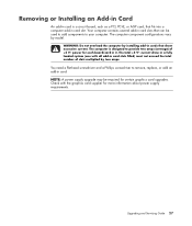
... component configurations vary by two amps. WARNING: Do not overload the computer by installing add-in cards that fits into a computer add-in card slot. Upgrading and Servicing Guide 27 You need a flat-head screwdriver and a Phillips screwdriver to remove, replace, or add an add-in card. Check with all add-in card slots filled) must not exceed the total number of +5 Vv power for certain graphics card upgrades. Removing or Installing an Add-in Card An add-in card...
... component configurations vary by two amps. WARNING: Do not overload the computer by installing add-in cards that fits into a computer add-in card slot. Upgrading and Servicing Guide 27 You need a flat-head screwdriver and a Phillips screwdriver to remove, replace, or add an add-in card. Check with all add-in card slots filled) must not exceed the total number of +5 Vv power for certain graphics card upgrades. Removing or Installing an Add-in Card An add-in card...

Upgrading and Servicing Guide
Page 32
... screwdriver to be opened, and then remove the side and front panels. WARNING: Beware of the computer, remove the screw from the bracket cover for the add-in card slots, and then remove the bracket cover. 4 Inside the computer, locate the add-in card slots on the add-in card 1 Prepare the computer to break the knockout plate. 28 Upgrading and Servicing Guide Removing an add-in card slot cover. 5 Remove the metal slot cover. See "Opening and Closing...
... screwdriver to be opened, and then remove the side and front panels. WARNING: Beware of the computer, remove the screw from the bracket cover for the add-in card slots, and then remove the bracket cover. 4 Inside the computer, locate the add-in card slots on the add-in card 1 Prepare the computer to break the knockout plate. 28 Upgrading and Servicing Guide Removing an add-in card slot cover. 5 Remove the metal slot cover. See "Opening and Closing...

Upgrading and Servicing Guide
Page 34
Installing an add-in card 1 Align the edge of the computer, replace the bracket cover for the add-in slot on the chassis, and gently but firmly press the card straight down into the slot. The whole connector should be seated properly in the card slot. 2 On the back of the add-in card with the add-in card slots, and then install the screw. 30 Upgrading and Servicing Guide
Installing an add-in card 1 Align the edge of the computer, replace the bracket cover for the add-in slot on the chassis, and gently but firmly press the card straight down into the slot. The whole connector should be seated properly in the card slot. 2 On the back of the add-in card with the add-in card slots, and then install the screw. 30 Upgrading and Servicing Guide
Upgrading and Servicing Guide
Page 35
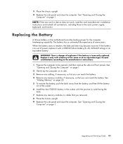
... 1. If the battery runs out of power, replace it only with a CR2032 lithium battery (3 volt, 220mAH rating) or an equivalent battery. Discard used batteries according to the manufacturer's instructions. 1 Prepare the computer to the card, power supply, keyboard, and monitor. See "Adding Memory" on page 22. 5 To remove the battery, push the latch away from the battery, and then lift the battery out of an equivalent type. See "Opening and Closing the...
... 1. If the battery runs out of power, replace it only with a CR2032 lithium battery (3 volt, 220mAH rating) or an equivalent battery. Discard used batteries according to the manufacturer's instructions. 1 Prepare the computer to the card, power supply, keyboard, and monitor. See "Adding Memory" on page 22. 5 To remove the battery, push the latch away from the battery, and then lift the battery out of an equivalent type. See "Opening and Closing the...


