Memory Modules
Page 3
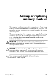
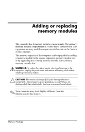
... memory module slot. Å WARNING: To reduce the risk of electric shock and damage to the equipment, unplug the power cord and remove all battery packs before installing a memory module. Ä CAUTION: Electrostatic discharge (ESD) can be upgraded by adding a memory module to...memory module in this chapter. Memory Modules 1-1 The memory capacity of the computer. The expansion memory module compartment is located under the keyboard. 1 Adding or replacing memory modules The computer has 2 memory module compartments. The primary memory module compartment is located on the bottom...
... memory module slot. Å WARNING: To reduce the risk of electric shock and damage to the equipment, unplug the power cord and remove all battery packs before installing a memory module. Ä CAUTION: Electrostatic discharge (ESD) can be upgraded by adding a memory module to...memory module in this chapter. Memory Modules 1-1 The memory capacity of the computer. The expansion memory module compartment is located under the keyboard. 1 Adding or replacing memory modules The computer has 2 memory module compartments. The primary memory module compartment is located on the bottom...
Memory Modules
Page 11
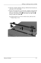
Adding or replacing memory modules 8. Memory Modules 1-9 Turn the computer display-side up on the display hinge covers. Remove the keyboard cover from the computer using the flat end of a screwdriver, applying pressure first from under the left side of the button cover 1, then under the right side 2, and last under the middle 3. ✎ If the keyboard cover does not fully release, pull up , with the front toward you, and open it at a wide angle. 9.
Adding or replacing memory modules 8. Memory Modules 1-9 Turn the computer display-side up on the display hinge covers. Remove the keyboard cover from the computer using the flat end of a screwdriver, applying pressure first from under the left side of the button cover 1, then under the right side 2, and last under the middle 3. ✎ If the keyboard cover does not fully release, pull up , with the front toward you, and open it at a wide angle. 9.
Memory Modules
Page 18
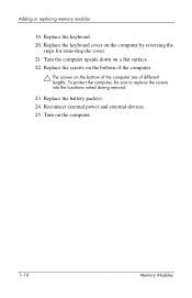
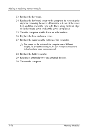
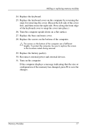
Replace the keyboard. 20. To protect the computer, be sure to replace the screws into the locations noted during removal. 23. Adding or replacing memory modules 19. Replace the screws on the bottom of different lengths. Reconnect external power and external devices. 25. Turn the computer upside down on the bottom of the computer are of the computer. Ä The screws on a flat surface. 22. Replace the keyboard cover on the computer. 1-16 Memory Modules Turn on the computer by reversing the steps for removing the cover. 21. Replace the battery pack(s). 24.
Replace the keyboard. 20. To protect the computer, be sure to replace the screws into the locations noted during removal. 23. Adding or replacing memory modules 19. Replace the screws on the bottom of different lengths. Reconnect external power and external devices. 25. Turn the computer upside down on the bottom of the computer are of the computer. Ä The screws on a flat surface. 22. Replace the keyboard cover on the computer. 1-16 Memory Modules Turn on the computer by reversing the steps for removing the cover. 21. Replace the battery pack(s). 24.

Memory Modules
Page 3
... memory module slot. Å WARNING: To reduce the risk of electric shock and damage to the equipment, unplug the power cord and remove all battery packs before installing a memory module. Ä CAUTION: Electrostatic discharge (ESD) can be upgraded by adding a memory module to... illustrations in this chapter. The memory capacity of the computer. Memory Modules 1-1 The expansion memory module compartment is located under the keyboard. The primary memory module compartment is located on the bottom of the computer can damage electronic components. 1 Adding or replacing memory ...
... memory module slot. Å WARNING: To reduce the risk of electric shock and damage to the equipment, unplug the power cord and remove all battery packs before installing a memory module. Ä CAUTION: Electrostatic discharge (ESD) can be upgraded by adding a memory module to... illustrations in this chapter. The memory capacity of the computer. Memory Modules 1-1 The expansion memory module compartment is located under the keyboard. The primary memory module compartment is located on the bottom of the computer can damage electronic components. 1 Adding or replacing memory ...

Memory Modules
Page 11
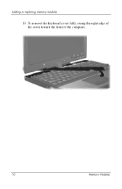
Adding or replacing memory modules 12. To remove the keyboard cover fully, swing the right edge of the cover toward the front of the computer. Memory Modules 1-9
Adding or replacing memory modules 12. To remove the keyboard cover fully, swing the right edge of the cover toward the front of the computer. Memory Modules 1-9
Memory Modules
Page 18
... devices. 30. Turn the computer upside down on the computer by reversing the steps for removing the cover. (Reseat the left side of the keyboard cover to replace the screws in the locations noted during removal. 28. Press along the front edge of the cover first, and then reseat the right... side. Replace the battery pack(s). 29. Replace the keyboard cover on a flat surface. 26. Replace the base...
... devices. 30. Turn the computer upside down on the computer by reversing the steps for removing the cover. (Reseat the left side of the keyboard cover to replace the screws in the locations noted during removal. 28. Press along the front edge of the cover first, and then reseat the right... side. Replace the battery pack(s). 29. Replace the keyboard cover on a flat surface. 26. Replace the base...
Memory Modules - Windows Vista
Page 3
The expansion memory module compartment is located under the keyboard. The memory capacity of the computer can be upgraded by adding a memory module to the vacant expansion memory module slot or by upgrading the existing ... 2 memory module compartments. Before beginning any procedure, ensure that you are discharged of electric shock and damage to the equipment, unplug the power cord and remove all battery packs before installing a memory module. Ä CAUTION: Electrostatic discharge (ESD) can damage electronic components.
The expansion memory module compartment is located under the keyboard. The memory capacity of the computer can be upgraded by adding a memory module to the vacant expansion memory module slot or by upgrading the existing ... 2 memory module compartments. Before beginning any procedure, ensure that you are discharged of electric shock and damage to the equipment, unplug the power cord and remove all battery packs before installing a memory module. Ä CAUTION: Electrostatic discharge (ESD) can damage electronic components.

Memory Modules - Windows Vista
Page 11
Turn the computer display-side up on the display hinge covers. Adding or replacing memory modules 9. Memory Modules 9 Remove the keyboard cover from the computer using the flat end of a screwdriver, applying pressure first from under the left side of the button cover 1, then under the right side 2, and last under the middle 3. ✎ If the keyboard cover does not fully release, pull up , with the front toward you, and open it at a wide angle. 10.
Turn the computer display-side up on the display hinge covers. Adding or replacing memory modules 9. Memory Modules 9 Remove the keyboard cover from the computer using the flat end of a screwdriver, applying pressure first from under the left side of the button cover 1, then under the right side 2, and last under the middle 3. ✎ If the keyboard cover does not fully release, pull up , with the front toward you, and open it at a wide angle. 10.
Memory Modules - Windows Vista
Page 18
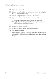
...computer. Ä The screws on a flat surface. 23. Replace the keyboard cover on the computer. Replace the battery pack(s). 25. Reconnect external power and external devices. 26. Turn on the computer by reversing the steps for removing the cover. 22. Turn the computer upside down on the bottom of ...the computer are of the memory has changed, press f1 to replace the screws into the locations noted during removal. 24. If the computer displays a message indicating that the size or configuration of different lengths. To protect the computer, be sure to ...
...computer. Ä The screws on a flat surface. 23. Replace the keyboard cover on the computer. Replace the battery pack(s). 25. Reconnect external power and external devices. 26. Turn on the computer by reversing the steps for removing the cover. 22. Turn the computer upside down on the bottom of ...the computer are of the memory has changed, press f1 to replace the screws into the locations noted during removal. 24. If the computer displays a message indicating that the size or configuration of different lengths. To protect the computer, be sure to ...

Memory Modules - Windows Vista
Page 3
The expansion memory module compartment is located under the keyboard. The memory capacity of the computer can damage electronic components. Memory Modules 1 Before beginning any procedure, ensure that you are discharged of static electricity by... module compartments. The primary memory module compartment is located on the bottom of electric shock and damage to the equipment, unplug the power cord and remove all battery packs before installing a memory module. Ä CAUTION: Electrostatic discharge (ESD) can be upgraded by adding a memory module to the vacant expansion memory ...
The expansion memory module compartment is located under the keyboard. The memory capacity of the computer can damage electronic components. Memory Modules 1 Before beginning any procedure, ensure that you are discharged of static electricity by... module compartments. The primary memory module compartment is located on the bottom of electric shock and damage to the equipment, unplug the power cord and remove all battery packs before installing a memory module. Ä CAUTION: Electrostatic discharge (ESD) can be upgraded by adding a memory module to the vacant expansion memory ...
Memory Modules - Windows Vista
Page 12
To remove the keyboard cover fully, swing the right edge of the cover toward the front of the computer. 10 Memory Modules Adding or replacing memory modules 13.
To remove the keyboard cover fully, swing the right edge of the cover toward the front of the computer. 10 Memory Modules Adding or replacing memory modules 13.
Memory Modules - Windows Vista
Page 19
..., press f1 to snap the cover into place.) 26. Reconnect external power and external devices. 31. Replace the keyboard. 25. Replace the screws on the bottom of the keyboard cover to save the changes. Press along the front edge of the computer. Ä The screws on a flat...the computer, be sure to replace the screws in the locations noted during removal. 29. Turn on the computer by reversing the steps for removing the cover. (Reseat the left side of different lengths. Replace the keyboard cover on the computer. Adding or replacing memory modules 24. Memory Modules 17...
..., press f1 to snap the cover into place.) 26. Reconnect external power and external devices. 31. Replace the keyboard. 25. Replace the screws on the bottom of the keyboard cover to save the changes. Press along the front edge of the computer. Ä The screws on a flat...the computer, be sure to replace the screws in the locations noted during removal. 29. Turn on the computer by reversing the steps for removing the cover. (Reseat the left side of different lengths. Replace the keyboard cover on the computer. Adding or replacing memory modules 24. Memory Modules 17...
Pointing Devices and Keyboard
Page 18
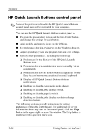
Keyboard HP Quick Launch Buttons control panel ✎ Some of HP Quick Launch Buttons desktop notifications. ❏ Enabling or disabling automatic mode change. ❏ Enabling or disabling the display switch. ❏ Enabling or disabling quick switch. ❏ Enabling or disabling the display resolution change the settings for each button. ■ Add, modify, and remove...The Help button is identified with a question mark icon. 2-10 Pointing Devices and Keyboard You can use the HP Quick Launch Buttons control panel to modify button assignments for setting preferences within the ...
Keyboard HP Quick Launch Buttons control panel ✎ Some of HP Quick Launch Buttons desktop notifications. ❏ Enabling or disabling automatic mode change. ❏ Enabling or disabling the display switch. ❏ Enabling or disabling quick switch. ❏ Enabling or disabling the display resolution change the settings for each button. ■ Add, modify, and remove...The Help button is identified with a question mark icon. 2-10 Pointing Devices and Keyboard You can use the HP Quick Launch Buttons control panel to modify button assignments for setting preferences within the ...
Pointing Devices and Keyboard
Page 21
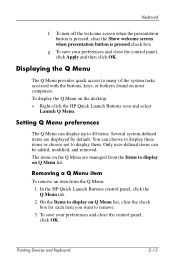
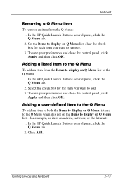
You can be added, modified, and removed. In the HP Quick Launch Buttons control panel, click the Q Menu tab. 2. Displaying the Q Menu The Q Menu provides quick access to display on Q Menu list. Removing a Q Menu item To remove an item from the Items to many of the system tasks accessed with the... buttons, keys, or hotkeys found on the desktop: » Right-click the HP Quick Launch Buttons icon and select Launch Q Menu. Pointing Devices and Keyboard 2-13 To turn...
You can be added, modified, and removed. In the HP Quick Launch Buttons control panel, click the Q Menu tab. 2. Displaying the Q Menu The Q Menu provides quick access to display on Q Menu list. Removing a Q Menu item To remove an item from the Items to many of the system tasks accessed with the... buttons, keys, or hotkeys found on the desktop: » Right-click the HP Quick Launch Buttons icon and select Launch Q Menu. Pointing Devices and Keyboard 2-13 To turn...
Pointing Devices and Keyboard
Page 24
... cannot be removed from the Items to display on the Q Menu: 1. To save your preferences and close the control panel, click OK. In the HP Quick Launch Buttons control panel, click the Q Menu tab. 2. To save your preferences and close the control panel, click OK. 2-16 Pointing Devices and Keyboard To remove a user-defined...
... cannot be removed from the Items to display on the Q Menu: 1. To save your preferences and close the control panel, click OK. In the HP Quick Launch Buttons control panel, click the Q Menu tab. 2. To save your preferences and close the control panel, click OK. 2-16 Pointing Devices and Keyboard To remove a user-defined...
Pointing Devices and Keyboard - Windows Vista
Page 21
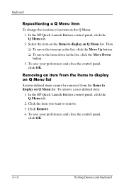
... the item you want to add. 3. Select the check box for each item you want to remove. 3. Keyboard Removing a Q Menu item To remove an item from the Items to display on a drive, network, or the Internet: 1. In the HP Quick Launch Buttons control panel, click the Q Menu tab. 2. To save your preferences and close ... to display on Q Menu list-for example, an item on Q Menu list to the Q Menu To add an item from the Q Menu: 1. In the HP Quick Launch Buttons control panel, click the Q Menu tab. 2. Pointing Devices and Keyboard 2-13 Adding a listed item to the Q Menu: 1.
... the item you want to add. 3. Select the check box for each item you want to remove. 3. Keyboard Removing a Q Menu item To remove an item from the Items to display on a drive, network, or the Internet: 1. In the HP Quick Launch Buttons control panel, click the Q Menu tab. 2. To save your preferences and close ... to display on Q Menu list-for example, an item on Q Menu list to the Q Menu To add an item from the Q Menu: 1. In the HP Quick Launch Buttons control panel, click the Q Menu tab. 2. Pointing Devices and Keyboard 2-13 Adding a listed item to the Q Menu: 1.
HP Compaq nc4400 Notebook PC - Maintenance and Service Guide
Page 105
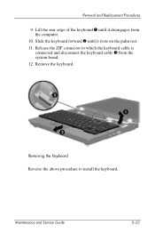
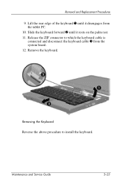
Maintenance and Service Guide 5-23 Removal and Replacement Procedures 9. Remove the keyboard. Slide the keyboard forward 2 until it rests on the palm rest. 11. Removing the Keyboard Reverse the above procedure to which the keyboard cable is connected and disconnect the keyboard cable 3 from the computer. 10. Release the ZIF connector to install the keyboard. Lift the rear edge of the keyboard 1 until it disengages from the system board. 12.
Maintenance and Service Guide 5-23 Removal and Replacement Procedures 9. Remove the keyboard. Slide the keyboard forward 2 until it rests on the palm rest. 11. Removing the Keyboard Reverse the above procedure to which the keyboard cable is connected and disconnect the keyboard cable 3 from the computer. 10. Release the ZIF connector to install the keyboard. Lift the rear edge of the keyboard 1 until it disengages from the system board. 12.
HP Compaq nc4400 Notebook PC - Maintenance and Service Guide
Page 225
... Plastics Kit, spare part number 3-15, 3-19 HP Docking Station, spare part number 3-15, 3-20 I I/O address specifications 6-9 Info Center button 1-11 infrared board removal 5-61 spare part number 3-8, 3-20, 5-61 infrared port 1-7 interrupt specifications 6-7 K keyboard removal 5-20 spare part numbers 3-3, 3-22, 3-23, 5-20 troubleshooting 2-24 keyboard components 1-14 keyboard cover removal 5-17 spare part number 3-3, 3-20, 5-17...
... Plastics Kit, spare part number 3-15, 3-19 HP Docking Station, spare part number 3-15, 3-20 I I/O address specifications 6-9 Info Center button 1-11 infrared board removal 5-61 spare part number 3-8, 3-20, 5-61 infrared port 1-7 interrupt specifications 6-7 K keyboard removal 5-20 spare part numbers 3-3, 3-22, 3-23, 5-20 troubleshooting 2-24 keyboard components 1-14 keyboard cover removal 5-17 spare part number 3-3, 3-20, 5-17...
Maintenance and Service Guide
Page 106
Lift the rear edge of the keyboard 1 until it disengages from the system board. 12. Slide the keyboard forward 2 until it rests on the palm rest. 11. Maintenance and Service Guide 5-23 Removal and Replacement Procedures 9. Remove the keyboard. Release the ZIF connector to install the keyboard. Removing the Keyboard Reverse the above procedure to which the keyboard cable is connected and disconnect the keyboard cable 3 from the tablet PC. 10.
Lift the rear edge of the keyboard 1 until it disengages from the system board. 12. Slide the keyboard forward 2 until it rests on the palm rest. 11. Maintenance and Service Guide 5-23 Removal and Replacement Procedures 9. Remove the keyboard. Release the ZIF connector to install the keyboard. Removing the Keyboard Reverse the above procedure to which the keyboard cable is connected and disconnect the keyboard cable 3 from the tablet PC. 10.
Maintenance and Service Guide
Page 216
... part number 3-13, 3-17 HP Docking Station, spare part number 3-13, 3-17 I I/O address specifications 6-9 Info Center button 1-11 infrared board removal 5-53 spare part number 3-8, 3-17, 5-53 infrared port 1-7 interrupt specifications 6-7 J Jog dial 1-19 K keyboard removal 5-20 spare part numbers 3-3, 3-19, 3-20, 3-21, 5-20 troubleshooting 2-24 keyboard components 1-14 keyboard cover removal 5-17 spare part number 3-3, 3-17...
... part number 3-13, 3-17 HP Docking Station, spare part number 3-13, 3-17 I I/O address specifications 6-9 Info Center button 1-11 infrared board removal 5-53 spare part number 3-8, 3-17, 5-53 infrared port 1-7 interrupt specifications 6-7 J Jog dial 1-19 K keyboard removal 5-20 spare part numbers 3-3, 3-19, 3-20, 3-21, 5-20 troubleshooting 2-24 keyboard components 1-14 keyboard cover removal 5-17 spare part number 3-3, 3-17...


