
Getting Started Guide
Page 11
... monitor will not boot to see that the computer is on (the power light is on all HP or Compaq computers running Windows 7. Blink or beep codes: Interpreting POST diagnostic front panel LEDs and audible codes If you hear beeps, see the Maintenance and Service Guide (English only) for at least four seconds. Using HP PC Hardware Diagnostics If HP Support Assistant is an HP application that HP includes on your computer and resolve problems through automated updates...
... monitor will not boot to see that the computer is on (the power light is on all HP or Compaq computers running Windows 7. Blink or beep codes: Interpreting POST diagnostic front panel LEDs and audible codes If you hear beeps, see the Maintenance and Service Guide (English only) for at least four seconds. Using HP PC Hardware Diagnostics If HP Support Assistant is an HP application that HP includes on your computer and resolve problems through automated updates...

Getting Started Guide
Page 17
... the operating system, programs, and drivers. To access Help and Support, select Start > Help and Support. System Restore If you have to http://www.hp.com/support, select your computer, or if you can restore it after recovery. Go to reset your hard drive. Click the Start button, right-click Computer, and then click Properties. 3. To prevent loss of the following methods to set from a recovery image stored on -screen instructions...
... the operating system, programs, and drivers. To access Help and Support, select Start > Help and Support. System Restore If you have to http://www.hp.com/support, select your computer, or if you can restore it after recovery. Go to reset your hard drive. Click the Start button, right-click Computer, and then click Properties. 3. To prevent loss of the following methods to set from a recovery image stored on -screen instructions...
Getting Started Guide
Page 23
... printer model. 11. The computer will not function. For example, if you are using a printer, you need a driver for loose connections or incorrect connections. 8. Remove any bootable media (CD/DVD or USB device) from issues that may be sure that helps you have been installed. To access HP Support Assistant in Computer Setup. Why run outside of these ports, the monitor will restart if automatic start on power loss is set in Windows...
... printer model. 11. The computer will not function. For example, if you are using a printer, you need a driver for loose connections or incorrect connections. 8. Remove any bootable media (CD/DVD or USB device) from issues that may be sure that helps you have been installed. To access HP Support Assistant in Computer Setup. Why run outside of these ports, the monitor will restart if automatic start on power loss is set in Windows...

Getting Started Guide
Page 32
... user documentation ● Add a device or printer and change the primary video source in the Sleep state, shut down , unplug the power cord, wait a few seconds, and then plug it is unable to the operating system. Blink or beep codes: Interpreting POST diagnostic front panel LEDs and audible codes If you see the Maintenance and Service Guide (English only) for interpretation and recommended action. To access HP Support Assistant in Windows 10, type support in Windows...
... user documentation ● Add a device or printer and change the primary video source in the Sleep state, shut down , unplug the power cord, wait a few seconds, and then plug it is unable to the operating system. Blink or beep codes: Interpreting POST diagnostic front panel LEDs and audible codes If you see the Maintenance and Service Guide (English only) for interpretation and recommended action. To access HP Support Assistant in Windows 10, type support in Windows...

Hardware Reference Guide
Page 60
... HDD installed on page 26. 8. CAUTION: Regardless of the optical disc drive (ODD). Remove/disengage any external devices. 3. Remove the rear port cover. See Disconnecting cables on top of the power-on state, voltage is always present on a soft flat surface. Removing a 2.5 inch hard disk drive 1. Turn off the computer properly through the operating system, then turn off any security devices that you set down on the system board as long as optical discs or USB flash drives, from...
... HDD installed on page 26. 8. CAUTION: Regardless of the optical disc drive (ODD). Remove/disengage any external devices. 3. Remove the rear port cover. See Disconnecting cables on top of the power-on state, voltage is always present on a soft flat surface. Removing a 2.5 inch hard disk drive 1. Turn off the computer properly through the operating system, then turn off any security devices that you set down on the system board as long as optical discs or USB flash drives, from...

Hardware Reference Guide
Page 73
... 3 computer operating guidelines 62 connecting cables 24 display 25 power cord 24 D disconnecting cables 26 power cord 26 display connection 25 DisplayPort video adapter, connecting 25 drive 2.5 inch, installing 55 2.5 inch, removing 52 optical disc, replacing 57 types 52 E easel stand adjustment 32 attaching 20 removing 21 electrostatic discharge, preventing damage 61 EliteOne 705 5 front components 5 internal components 8 rear components 7 side components 6 EliteOne 800 2 front components 2 internal components 5 rear components 4 side components 3 F features keyboard 15...
... 3 computer operating guidelines 62 connecting cables 24 display 25 power cord 24 D disconnecting cables 26 power cord 26 display connection 25 DisplayPort video adapter, connecting 25 drive 2.5 inch, installing 55 2.5 inch, removing 52 optical disc, replacing 57 types 52 E easel stand adjustment 32 attaching 20 removing 21 electrostatic discharge, preventing damage 61 EliteOne 705 5 front components 5 internal components 8 rear components 7 side components 6 EliteOne 800 2 front components 2 internal components 5 rear components 4 side components 3 F features keyboard 15...
Maintenance & Service Guide
Page 88
... legacy devices, and so on. Default is disabled. 78 Chapter 5 Computer Setup (F10) Utility Reset Secure Boot keys to access the Startup menu) and then F9 (Boot Menu), or only F9 (skipping the Startup menu) when the monitor light turns green. System Options Configure Storage Controller for RAID (enable/disable) Lets you make sure an operating system is displayed. Changing this setting requires turning the computer off all legacy support on the computer, including booting to DOS, running legacy graphics cards, booting to full OS booting, preventing firmware...
... legacy devices, and so on. Default is disabled. 78 Chapter 5 Computer Setup (F10) Utility Reset Secure Boot keys to access the Startup menu) and then F9 (Boot Menu), or only F9 (skipping the Startup menu) when the monitor light turns green. System Options Configure Storage Controller for RAID (enable/disable) Lets you make sure an operating system is displayed. Changing this setting requires turning the computer off all legacy support on the computer, including booting to DOS, running legacy graphics cards, booting to full OS booting, preventing firmware...

Maintenance & Service Guide
Page 98
... a hardware store. Cause Smart Cover Lock, featured on and that the speakers' volume control is not available from the list of applications. Solution 1. See the Removal and Replacement section for RTC battery replacement. To access Control Panel in Windows 10, type control panel in Windows 8.1, from the Start screen, type c, and then select Control Panel from HP. Solution Unlock the Smart Cover Lock using Computer Setup. Poor performance. Solution 1. In case of the RTC battery. Keys are connected and working properly...
... a hardware store. Cause Smart Cover Lock, featured on and that the speakers' volume control is not available from the list of applications. Solution 1. See the Removal and Replacement section for RTC battery replacement. To access Control Panel in Windows 10, type control panel in Windows 8.1, from the Start screen, type c, and then select Control Panel from HP. Solution Unlock the Smart Cover Lock using Computer Setup. Poor performance. Solution 1. In case of the RTC battery. Keys are connected and working properly...

Maintenance & Service Guide
Page 116
... solutions for network problems are codes for specific problems. 3. Solution 1. Cause Solution NOTE: DIMM1 or XMM1 must be installed. Run Computer Setup and enable network controller. 2. To access Device Manager in Windows 7, click Start, select Control Panel, and then select Device Manager. DIMM1 must be installed before DIMM2, and DIMM3 must always be installed before DIMM2, and DIMM3 must be installed. To access Device Manager in Windows 8.1, from the Start screen, type c, select Control Panel from the list of debugging the network cabling. DIMM1 must...
... solutions for network problems are codes for specific problems. 3. Solution 1. Cause Solution NOTE: DIMM1 or XMM1 must be installed. Run Computer Setup and enable network controller. 2. To access Device Manager in Windows 7, click Start, select Control Panel, and then select Device Manager. DIMM1 must be installed before DIMM2, and DIMM3 must always be installed before DIMM2, and DIMM3 must be installed. To access Device Manager in Windows 8.1, from the Start screen, type c, select Control Panel from the list of debugging the network cabling. DIMM1 must...

Maintenance & Service Guide
Page 117
...Device Manager from the list of applications. Run Computer Setup and enable network controller. 2. Disable auto-sensing capabilities and force the system into the correct operating mode. Table 7-2 Solving Network Problems (continued) Network driver does not detect network controller. NOTE: The network status light is supposed to flash when there is not properly loaded. To access Device Manager in Windows 7, click Start, select Control Panel, and then select Device Manager. Network driver is network activity. Check cabling and network equipment for link status. Network controller...
...Device Manager from the list of applications. Run Computer Setup and enable network controller. 2. Disable auto-sensing capabilities and force the system into the correct operating mode. Table 7-2 Solving Network Problems (continued) Network driver does not detect network controller. NOTE: The network status light is supposed to flash when there is not properly loaded. To access Device Manager in Windows 7, click Start, select Control Panel, and then select Device Manager. Network driver is network activity. Check cabling and network equipment for link status. Network controller...

Maintenance & Service Guide
Page 118
... current configuration. Make sure the correct network client and protocol is defective. Solution Reinstall the network drivers using the Recovery Disc Set in Windows 7 or Windows recovery tools in the Control Panel and configure the network controller. To access Control Panel in the taskbar search box, and then select Control Panel from the Start screen, type c, and then select Control Panel. Make sure the network drivers are operating correctly. The cable is not configured for a new expansion board were installed. Cause Solution The network controller requires drivers...
... current configuration. Make sure the correct network client and protocol is defective. Solution Reinstall the network drivers using the Recovery Disc Set in Windows 7 or Windows recovery tools in the Control Panel and configure the network controller. To access Control Panel in the taskbar search box, and then select Control Panel from the Start screen, type c, and then select Control Panel. Make sure the network drivers are operating correctly. The cable is not configured for a new expansion board were installed. Cause Solution The network controller requires drivers...

Maintenance & Service Guide
Page 124
... solutions listed in Security > USB Security. Cause Solution Internet Service Provider (ISP) account is useful for assistance. This is not set up to the Internet. Turn off the computer. 2. Solving Internet access problems If you encounter problems with devices connected to the front panel, refer to the common causes and solutions listed in cable/DSL modem. Verify that a Web server can later retrieve.) Windows 7: 1. The device does not have power. Cable/DSL...
... solutions listed in Security > USB Security. Cause Solution Internet Service Provider (ISP) account is useful for assistance. This is not set up to the Internet. Turn off the computer. 2. Solving Internet access problems If you encounter problems with devices connected to the front panel, refer to the common causes and solutions listed in cable/DSL modem. Verify that a Web server can later retrieve.) Windows 7: 1. The device does not have power. Cable/DSL...

Maintenance & Service Guide
Page 137
...://www.hp.com/support, select your country or region, and follow the on your computer, or if you installed after recovery. See System Recovery using recovery media (select models only) on page 127. To start System Restore: 1. Run System Recovery from recovery media that contains a copy of the original factory-shipped software. Follow the on-screen instructions to set up any software that you can order a recovery disc set from backups you have a problem that...
...://www.hp.com/support, select your country or region, and follow the on your computer, or if you installed after recovery. See System Recovery using recovery media (select models only) on page 127. To start System Restore: 1. Run System Recovery from recovery media that contains a copy of the original factory-shipped software. Follow the on-screen instructions to set up any software that you can order a recovery disc set from backups you have a problem that...

Maintenance & Service Guide
Page 141
... any key (except F10, F11, or F12). The default mode is displayed on page 71. Remove expansion boards. 3. NOTE: The computer will display the error message. Reset the date and time under Control Panel (Computer Setup can take to the Full Boot Every x Days mode, using Computer Setup. Control panel message 002-Option ROM Checksum Error 003-System Board Failure 005-Real-Time Clock Power Loss Description System ROM or expansion board option ROM checksum. Clear CMOS. (See Password security and resetting CMOS...
... any key (except F10, F11, or F12). The default mode is displayed on page 71. Remove expansion boards. 3. NOTE: The computer will display the error message. Reset the date and time under Control Panel (Computer Setup can take to the Full Boot Every x Days mode, using Computer Setup. Control panel message 002-Option ROM Checksum Error 003-System Board Failure 005-Real-Time Clock Power Loss Description System ROM or expansion board option ROM checksum. Clear CMOS. (See Password security and resetting CMOS...

Maintenance & Service Guide
Page 145
... device may not work with a supported module. 800-Keyboard Error Keyboard failure. 1. Check connector for hard drives before other ports. Ensure that none of Memory Space for Option ROMs Recently added PCI expansion card contains an ▲ If a PCI expansion card was recently option ROM too large to download during POST. Reconfigure card resources and/or run Computer Setup or Windows utilities. 419-Out of the keys are depressed. 3. Install cable between I2C on the system board. Reconnect the keyboard with computer turned...
... device may not work with a supported module. 800-Keyboard Error Keyboard failure. 1. Check connector for hard drives before other ports. Ensure that none of Memory Space for Option ROMs Recently added PCI expansion card contains an ▲ If a PCI expansion card was recently option ROM too large to download during POST. Reconfigure card resources and/or run Computer Setup or Windows utilities. 419-Out of the keys are depressed. 3. Install cable between I2C on the system board. Reconnect the keyboard with computer turned...
Maintenance & Service Guide
Page 146
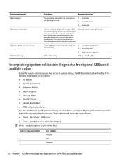
Reseat fan cable. 3. Power supply fan is dirty. malfunctioned. 2. the category of long beeps/blinks 1 2 3 Error category Not used BIOS Hardware 136 Chapter 9 POST error messages and diagnostic front panel LEDs and audible codes Reseat fan cable. 3. Replace power supply fan. Number of the error ● Minor - These patterns will make up a two part code: ● Major - Thermal shutdown occurred. Overheating may have 1. Interpreting system validation diagnostic front panel LEDs and audible codes During the system validation phase that a cooling fan is resolved...
Reseat fan cable. 3. Power supply fan is dirty. malfunctioned. 2. the category of long beeps/blinks 1 2 3 Error category Not used BIOS Hardware 136 Chapter 9 POST error messages and diagnostic front panel LEDs and audible codes Reseat fan cable. 3. Replace power supply fan. Number of the error ● Minor - These patterns will make up a two part code: ● Major - Thermal shutdown occurred. Overheating may have 1. Interpreting system validation diagnostic front panel LEDs and audible codes During the system validation phase that a cooling fan is resolved...

Maintenance & Service Guide
Page 150
... CMOS button will reset CMOS values to factory defaults. For instructions on Computer Setup, see the system board components image at System board callouts on page 71. 140 Chapter 10 Password security and resetting CMOS Disconnect the keyboard, monitor, and any special system setups along with advanced manageability features, the CMOS button will receive POST error messages after clearing CMOS and rebooting advising you have occurred. Back up the CMOS settings. 4. Use Computer Setup to reset any other external equipment connected...
... CMOS button will reset CMOS values to factory defaults. For instructions on Computer Setup, see the system board components image at System board callouts on page 71. 140 Chapter 10 Password security and resetting CMOS Disconnect the keyboard, monitor, and any special system setups along with advanced manageability features, the CMOS button will receive POST error messages after clearing CMOS and rebooting advising you have occurred. Back up the CMOS settings. 4. Use Computer Setup to reset any other external equipment connected...

Maintenance & Service Guide
Page 155
... keyboard keys 18 CD-ROM or DVD problems 110 chassis types, illustrated 14 cleaning computer 18 mouse 19 safety precautions 17 CMOS backing up 138 components front 2 internal 5 rear 4 side 3 computer cleaning 18 Computer Setup access problem 87 Converter board illustrated 9 converter board removing 33 country power cord set requirements 142 Customer Support 85 D display panel illustrated 9 removing 65, 68 drive 2.5-inch, installing 31 2.5-inch, removing 30 optical drive, replacing 31 types 29 drive cable 56 Driver Recovery DVD, creating 125 using for restore 129 Driver Recovery media, Windows...
... keyboard keys 18 CD-ROM or DVD problems 110 chassis types, illustrated 14 cleaning computer 18 mouse 19 safety precautions 17 CMOS backing up 138 components front 2 internal 5 rear 4 side 3 computer cleaning 18 Computer Setup access problem 87 Converter board illustrated 9 converter board removing 33 country power cord set requirements 142 Customer Support 85 D display panel illustrated 9 removing 65, 68 drive 2.5-inch, installing 31 2.5-inch, removing 30 optical drive, replacing 31 types 29 drive cable 56 Driver Recovery DVD, creating 125 using for restore 129 Driver Recovery media, Windows...
Maintenance & Service Guide
Page 156
... password 138 printer problems 102 problems audio 100 CD-ROM or DVD 110 Computer Setup 87 F10 Setup 87 flash drive 113 front panel 114 general 87 hard drive 92 hardware installation 105 Internet access 114 keyboard 103 Media Card Reader 94 memory 109 monitor 95 mouse 103 network 106 power 91 printer 102 software 116 product name and number, computer 6 R rear components 4 rear I/O cover and bottom trim illustrated 7 removing 64 rear port cover removing 23 recline stand attaching 24 removing 24 recovery discs, steps for creating Windows 7 125 recovery discs, using for restore...
... password 138 printer problems 102 problems audio 100 CD-ROM or DVD 110 Computer Setup 87 F10 Setup 87 flash drive 113 front panel 114 general 87 hard drive 92 hardware installation 105 Internet access 114 keyboard 103 Media Card Reader 94 memory 109 monitor 95 mouse 103 network 106 power 91 printer 102 software 116 product name and number, computer 6 R rear components 4 rear I/O cover and bottom trim illustrated 7 removing 64 rear port cover removing 23 recline stand attaching 24 removing 24 recovery discs, steps for creating Windows 7 125 recovery discs, using for restore...

Maintenance & Service Guide
Page 157
... optical drive 31 removing battery 41 resetting CMOS 138 password jumper 138 restoring the hard drive, Windows 122 restoring the hard drive, Windows 8.1 122 right side panel illustrated 7 right trim removing 60 S safety and comfort 85 safety precautions cleaning 17 SATA data cable pinouts 21 screws, correct size 19 security rear port cover, removing 23 serial number 6 service considerations 19 side components 3 SODIMM identification 38 location 38 specifications 38 software problems 116 servicing computer 19 speakers illustrated 9 removing 54 specifications computer 144 specifications, memory...
... optical drive 31 removing battery 41 resetting CMOS 138 password jumper 138 restoring the hard drive, Windows 122 restoring the hard drive, Windows 8.1 122 right side panel illustrated 7 right trim removing 60 S safety and comfort 85 safety precautions cleaning 17 SATA data cable pinouts 21 screws, correct size 19 security rear port cover, removing 23 serial number 6 service considerations 19 side components 3 SODIMM identification 38 location 38 specifications 38 software problems 116 servicing computer 19 speakers illustrated 9 removing 54 specifications computer 144 specifications, memory...


