HP LaserJet Printer Family - Print Media Specification Guide
Page 12
... optimized for your paper supplier. Print quality from the HP color LaserJet printers is premium paper that you are printed on page 9). however, the pH should last as long as carbonless paper, can cause swelling of rollers, damage to the paper path, or buildup on white... uses cotton fiber, and is because HP color LaserJet printers create colors by petroleum-based solvents or plasticizers, such as standard paper (see "Guidelines for using , it cannot adjust the output colors for colored paper. Toner is used for laser printers. Avoid folding archival documents across printed ...
... optimized for your paper supplier. Print quality from the HP color LaserJet printers is premium paper that you are printed on page 9). however, the pH should last as long as carbonless paper, can cause swelling of rollers, damage to the paper path, or buildup on white... uses cotton fiber, and is because HP color LaserJet printers create colors by petroleum-based solvents or plasticizers, such as standard paper (see "Guidelines for using , it cannot adjust the output colors for colored paper. Toner is used for laser printers. Avoid folding archival documents across printed ...
HP LaserJet Printer Family - Print Media Specification Guide
Page 48
...lose moisture depending on the humidity in the air around it. packaging Packaging is required in an HP LaserJet printer, because adequate packaging maintains the correct level of moisture and protects paper from damage during printing, ...rollers inside of air flow between the sheet surface and a flat reference surface. Moisture content can also affect other paper properties such as multifunction product or multifunction printer. perforations A hole or series of paper. photocopy paper See copier paper. post-consumer waste Manufactured material that are used in HP LaserJet printers...
...lose moisture depending on the humidity in the air around it. packaging Packaging is required in an HP LaserJet printer, because adequate packaging maintains the correct level of moisture and protects paper from damage during printing, ...rollers inside of air flow between the sheet surface and a flat reference surface. Moisture content can also affect other paper properties such as multifunction product or multifunction printer. perforations A hole or series of paper. photocopy paper See copier paper. post-consumer waste Manufactured material that are used in HP LaserJet printers...

HP LaserJet Printer Family - Print Media Specification Guide
Page 54
...opening 5 storing 19 recycled paper HP 37 specifications 8 resistivity, electrical defined 40 paper specifications 10 transparency specifications 16 rollers, swelling of 6 rough papers 4, 6 roughness defined 43 envelope specifications 13 paper specifications 10 S Sales and Service Offices, HP 2 scanning laser beam, operations of 2 sealers... 12, 32 paper, standard 31 smeared toner, troubleshooting 28 smoothness defined 41, 42 equivalence tables 33 soft gloss laser paper, hp 36 sorting mailings 18 specialty papers 8, 9 stamps, precanceled 18 standard sizes card stock 32 envelopes 32 paper 31...
...opening 5 storing 19 recycled paper HP 37 specifications 8 resistivity, electrical defined 40 paper specifications 10 transparency specifications 16 rollers, swelling of 6 rough papers 4, 6 roughness defined 43 envelope specifications 13 paper specifications 10 S Sales and Service Offices, HP 2 scanning laser beam, operations of 2 sealers... 12, 32 paper, standard 31 smeared toner, troubleshooting 28 smoothness defined 41, 42 equivalence tables 33 soft gloss laser paper, hp 36 sorting mailings 18 specialty papers 8, 9 stamps, precanceled 18 standard sizes card stock 32 envelopes 32 paper 31...

HP LaserJet P3005 - User Guide
Page 110
Remove the new print cartridge from the new print cartridge. Place the used print cartridge from the device. 3. CAUTION Do not touch the shutter or the surface of the print cartridge and distribute the toner by gently rocking the print cartridge. Remove the shipping tape from the bag. Discard the shipping tape according to local regulations. 98 Chapter 6 Manage and maintain the device ENWW Grasp both sides of the roller. 5. 2. Remove the used print cartridge in the bag for recycling. 4.
Remove the new print cartridge from the new print cartridge. Place the used print cartridge from the device. 3. CAUTION Do not touch the shutter or the surface of the print cartridge and distribute the toner by gently rocking the print cartridge. Remove the shipping tape from the bag. Discard the shipping tape according to local regulations. 98 Chapter 6 Manage and maintain the device ENWW Grasp both sides of the roller. 5. 2. Remove the used print cartridge in the bag for recycling. 4.

HP LaserJet P3005 - User Guide
Page 132
The device is performing an internal test. possible jams. Checking printer CHOSEN PERSONALITY NOT AVAILABLE alternates with a genuine HP supply that did not exist in the process of the cleaning process. No action necessary. ● Press to eject these pages automatically. ...engine is waiting for No action necessary. To continue press CLEANING DISK X% COMPLETE alternates with Ready The device received data and is turning the rollers to an hour. This process might be printed. Clearing event log This message appears while the event log is paused. The device returns ...
The device is performing an internal test. possible jams. Checking printer CHOSEN PERSONALITY NOT AVAILABLE alternates with a genuine HP supply that did not exist in the process of the cleaning process. No action necessary. ● Press to eject these pages automatically. ...engine is waiting for No action necessary. To continue press CLEANING DISK X% COMPLETE alternates with Ready The device received data and is turning the rollers to an hour. This process might be printed. Clearing event log This message appears while the event log is paused. The device returns ...
HP LaserJet P3005 - User Guide
Page 139
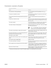
...you to replace supplies, or print a supplies status page to stick together. The internal rollers from the tray. Device supply items have reached the end of media. Make sure that meets HP specifications. Remove the media, flex it, rotate it 180°, or flip it . ...life of the supplies. page completely settles in a controlled environment. 1 If the device still continues to jam, contact HP Customer Support or your authorized HP service provider. Reload the media into the output bin. Check the device control panel for messages prompting you removed the...
...you to replace supplies, or print a supplies status page to stick together. The internal rollers from the tray. Device supply items have reached the end of media. Make sure that meets HP specifications. Remove the media, flex it, rotate it 180°, or flip it . ...life of the supplies. page completely settles in a controlled environment. 1 If the device still continues to jam, contact HP Customer Support or your authorized HP service provider. Reload the media into the output bin. Check the device control panel for messages prompting you removed the...

HP LaserJet P3005 - User Guide
Page 177
... and other parts with the device. Check with your device needs to be returned to HP for repair, follow the steps below to the print cartridge, avoid touching the roller on -site visits for organizations with a selection of response times. Extended coverage hours and... extended travel beyond HP's designated service zones are not part of inadequate packing is designated for additional charges). Repacking the device If HP Customer Care determines that...
... and other parts with the device. Check with your device needs to be returned to HP for repair, follow the steps below to the print cartridge, avoid touching the roller on -site visits for organizations with a selection of response times. Extended coverage hours and... extended travel beyond HP's designated service zones are not part of inadequate packing is designated for additional charges). Repacking the device If HP Customer Care determines that...
Service Manual
Page 7
......72 I/O cover ...72 Top, right cover ...73 Top cover ...74 Front, right cover ...75 Control panel ...78 Formatter ...80 Fuser ...83 Laser/scanner ...86 Engine control unit (ECU) ...88 Access plate ...96 High-voltage power supply ...97 Paper feed guide assembly ...104 Main motor ...106 ... notes for the gear assembly 110 Tray 1 solenoid ...111 Tray 2 solenoid ...112 E-label reader (memory tag) ...113 Face-down-roller shaft ...115 Cartridge door ...117 Transfer roller ...120 Registration assembly ...121 Tray 1 pickup roller ...124 Tray 2 pickup roller ...125 Separation pad ...127 ENWW v
......72 I/O cover ...72 Top, right cover ...73 Top cover ...74 Front, right cover ...75 Control panel ...78 Formatter ...80 Fuser ...83 Laser/scanner ...86 Engine control unit (ECU) ...88 Access plate ...96 High-voltage power supply ...97 Paper feed guide assembly ...104 Main motor ...106 ... notes for the gear assembly 110 Tray 1 solenoid ...111 Tray 2 solenoid ...112 E-label reader (memory tag) ...113 Face-down-roller shaft ...115 Cartridge door ...117 Transfer roller ...120 Registration assembly ...121 Tray 1 pickup roller ...124 Tray 2 pickup roller ...125 Separation pad ...127 ENWW v

Service Manual
Page 16
...5 100 Figure 5-35 Removing the power supply (5 of 5 101 Figure 5-36 Grounding-spring locations ...102 Figure 5-37 Reinstalling the oblique-roller assembly 103 Figure 5-38 Removing the paper feed guide assembly 104 Figure 5-39 Removing the main motor (1 of 2 106 Figure 5-40 ... 117 Figure 5-51 Removing the cartridge door (2 of 3 118 Figure 5-52 Removing the cartridge door (3 of 3 119 Figure 5-53 Removing the transfer roller ...120 Figure 5-54 Removing the registration assembly (1 of 3 121 Figure 5-55 Removing the registration assembly (2 of 3 122 Figure 5-56 Removing the registration ...
...5 100 Figure 5-35 Removing the power supply (5 of 5 101 Figure 5-36 Grounding-spring locations ...102 Figure 5-37 Reinstalling the oblique-roller assembly 103 Figure 5-38 Removing the paper feed guide assembly 104 Figure 5-39 Removing the main motor (1 of 2 106 Figure 5-40 ... 117 Figure 5-51 Removing the cartridge door (2 of 3 118 Figure 5-52 Removing the cartridge door (3 of 3 119 Figure 5-53 Removing the transfer roller ...120 Figure 5-54 Removing the registration assembly (1 of 3 121 Figure 5-55 Removing the registration assembly (2 of 3 122 Figure 5-56 Removing the registration ...

Service Manual
Page 42
Discard the shipping tape according to local regulations. 24 Chapter 2 Installation and configuration ENWW Remove the used print cartridge in the bag for recycling. 4. Remove the new print cartridge from the device. 3. Grasp both sides of the roller. 5. Remove the shipping tape from the new print cartridge. CAUTION Do not touch the shutter or the surface of the print cartridge and distribute the toner by gently rocking the print cartridge. Place the used print cartridge from the bag. 2.
Discard the shipping tape according to local regulations. 24 Chapter 2 Installation and configuration ENWW Remove the used print cartridge in the bag for recycling. 4. Remove the new print cartridge from the device. 3. Grasp both sides of the roller. 5. Remove the shipping tape from the new print cartridge. CAUTION Do not touch the shutter or the surface of the print cartridge and distribute the toner by gently rocking the print cartridge. Place the used print cartridge from the bag. 2.
Service Manual
Page 65
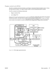
Figure 4-3 Engine control system circuit diagram on the ECU. Rear output bin Output bin LASER/SCANNER SYSTEM Scanning mirror Laser diode BD circuit Scanner motor IMAGE Primary charging FORMATION roller SYSTEM Developing unit Fuser PhotoCleaning unit sensitive drum Transfer charging roller Duplex feed unit Tray 2 Tray 2 pickup unit ECU Engine controller PCA High-voltage Power...
Figure 4-3 Engine control system circuit diagram on the ECU. Rear output bin Output bin LASER/SCANNER SYSTEM Scanning mirror Laser diode BD circuit Scanner motor IMAGE Primary charging FORMATION roller SYSTEM Developing unit Fuser PhotoCleaning unit sensitive drum Transfer charging roller Duplex feed unit Tray 2 Tray 2 pickup unit ECU Engine controller PCA High-voltage Power...
Service Manual
Page 68
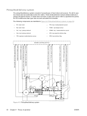
...-bin delivery flag ● SR2, fuser-delivery flag Figure 4-5 Pickup/feed/delivery system 50 Chapter 4 Theory of feed rollers and sensors. The ECU uses two motors and two solenoids to drive the rollers. Pickup/feed/delivery system The pickup/feed/delivery system consists of several types of operation ENWW If media does...
...-bin delivery flag ● SR2, fuser-delivery flag Figure 4-5 Pickup/feed/delivery system 50 Chapter 4 Theory of feed rollers and sensors. The ECU uses two motors and two solenoids to drive the rollers. Pickup/feed/delivery system The pickup/feed/delivery system consists of several types of operation ENWW If media does...

Service Manual
Page 71
... 3: Developing The developing cylinder comes in Figure 4-10 Developing on page 53. Figure 4-9 Primary charging Step 2: Laser beam exposure The laser beam scans the photosensitive drum to neutralize negative charges on parts of the drum are shown as positive in contact ...with the photosensitive drum to the photosensitive drum. Figure 4-10 Developing ENWW Basic operation 53 The charges are actually negative, but they are applied to the primary charging roller...
... 3: Developing The developing cylinder comes in Figure 4-10 Developing on page 53. Figure 4-9 Primary charging Step 2: Laser beam exposure The laser beam scans the photosensitive drum to neutralize negative charges on parts of the drum are shown as positive in contact ...with the photosensitive drum to the photosensitive drum. Figure 4-10 Developing ENWW Basic operation 53 The charges are actually negative, but they are applied to the primary charging roller...

Service Manual
Page 72
Step 4: Transfer The transfer charging roller, to the fusing film strengthens the holding force of the toner on the print media and prevents the toner from scattering. 54 Chapter 4 Theory of ...the print media causes its separation from the developing cylinder and the blade. The image on the print media. Photosensitive drum Media Transfer roller Figure 4-11 Transfer Step 5: Separation The elasticity of operation ENWW Figure 4-12 Separation Step 6: Fusing The DC negative bias applied to which a DC positive bias...
Step 4: Transfer The transfer charging roller, to the fusing film strengthens the holding force of the toner on the print media and prevents the toner from scattering. 54 Chapter 4 Theory of ...the print media causes its separation from the developing cylinder and the blade. The image on the print media. Photosensitive drum Media Transfer roller Figure 4-11 Transfer Step 5: Separation The elasticity of operation ENWW Figure 4-12 Separation Step 6: Fusing The DC negative bias applied to which a DC positive bias...

Service Manual
Page 74
Internal components Figure 4-15 Cross-section of device on page 56 highlights the major internal components. 1 2 3 4 56 7 8 18 17 16 15 14 13 12 11 10 9 Figure 4-15 Cross-section of device 1 Top output-bin delivery roller 2 Fuser roller, fuser assembly 3 Laser/scanner 4 Photosensitive drum, print cartridge 5 Print cartridge 6 Registration assembly 7 Tray 1 pickup roller 56 Chapter 4 Theory of operation ENWW
Internal components Figure 4-15 Cross-section of device on page 56 highlights the major internal components. 1 2 3 4 56 7 8 18 17 16 15 14 13 12 11 10 9 Figure 4-15 Cross-section of device 1 Top output-bin delivery roller 2 Fuser roller, fuser assembly 3 Laser/scanner 4 Photosensitive drum, print cartridge 5 Print cartridge 6 Registration assembly 7 Tray 1 pickup roller 56 Chapter 4 Theory of operation ENWW

Service Manual
Page 76
...and sensor detects the trailing edge of the media. Fuser-motor initial drive Laser/scanner-motor initial drive High-voltage control Detection of the presence of a print cartridge Cleaning of the transfer roller after the primary charging AC bias is turned on page 58 describes engine ...operations for printing. Timing The microprocessor on Failure/abnormality check: detection of laser/scanner failure, fuser failure, and open covers Communication with ...
...and sensor detects the trailing edge of the media. Fuser-motor initial drive Laser/scanner-motor initial drive High-voltage control Detection of the presence of a print cartridge Cleaning of the transfer roller after the primary charging AC bias is turned on page 58 describes engine ...operations for printing. Timing The microprocessor on Failure/abnormality check: detection of laser/scanner failure, fuser failure, and open covers Communication with ...

Service Manual
Page 81
...and replacement Chapter contents ● Overview ● Service approach ● Covers ● Control panel ● Formatter ● Fuser ● Laser/scanner ● Engine control unit (ECU) ● Access plate ● High-voltage power supply ● Paper feed guide assembly ● ... for the gear assembly ● Tray 1 solenoid ● Tray 2 solenoid ● E-label reader (memory tag) ● Face-down-roller shaft ● Cartridge door ● Transfer roller ● Registration assembly ● Tray 1 pickup roller ● Tray 2 pickup roller ENWW Chapter contents 63
...and replacement Chapter contents ● Overview ● Service approach ● Covers ● Control panel ● Formatter ● Fuser ● Laser/scanner ● Engine control unit (ECU) ● Access plate ● High-voltage power supply ● Paper feed guide assembly ● ... for the gear assembly ● Tray 1 solenoid ● Tray 2 solenoid ● E-label reader (memory tag) ● Face-down-roller shaft ● Cartridge door ● Transfer roller ● Registration assembly ● Tray 1 pickup roller ● Tray 2 pickup roller ENWW Chapter contents 63

Service Manual
Page 117
5. At the bottom of the device, remove the two screws (callout 4) that secure the oblique-roller assembly to the device, and then lift the assembly from the device. 4 Figure 5-33 Removing the power supply (3 of 5) ENWW High-voltage power supply 99
5. At the bottom of the device, remove the two screws (callout 4) that secure the oblique-roller assembly to the device, and then lift the assembly from the device. 4 Figure 5-33 Removing the power supply (3 of 5) ENWW High-voltage power supply 99

Service Manual
Page 120
Verify that the roller lever (callout 11) is not misaligned. 102 Chapter 5 Removal and replacement ENWW 9. As you remove the power supply, note the location of the assembly. You might need to align the gears. Rotate the roller toward the back of the device to reinstall the spring before reinstalling the power supply. 9 Figure 5-36 Grounding-spring locations Reinstallation tip To reinstall the oblique-roller assembly, slide the tab (callout 10) in first and then insert the other side of the non-captive grounding spring (callout 9).
Verify that the roller lever (callout 11) is not misaligned. 102 Chapter 5 Removal and replacement ENWW 9. As you remove the power supply, note the location of the assembly. You might need to align the gears. Rotate the roller toward the back of the device to reinstall the spring before reinstalling the power supply. 9 Figure 5-36 Grounding-spring locations Reinstallation tip To reinstall the oblique-roller assembly, slide the tab (callout 10) in first and then insert the other side of the non-captive grounding spring (callout 9).

Service Manual
Page 121
You do not have to separate the power supply and the power-supply pan. ENWW High-voltage power supply 103 11 10 Figure 5-37 Reinstalling the oblique-roller assembly NOTE The power supply and the power-supply pan together are a single FRU.
You do not have to separate the power supply and the power-supply pan. ENWW High-voltage power supply 103 11 10 Figure 5-37 Reinstalling the oblique-roller assembly NOTE The power supply and the power-supply pan together are a single FRU.


