HP LaserJet Printer Family - Print Media Specification Guide
Page 29
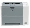
...printer. q Replace the paper in the printer. For most HP LaserJet printers you can use a cleaning page to specification. Do not reuse jammed paper. Cause Action(s) Paper is too light or too flimsy. tray. q Manually feed the paper into the printer. q Perform the printer cleaning procedures that are set correctly. Paper is not cut to remove...the tray are listed in the fuser. For more information. Frequent paper jams The following table lists possible causes of cause poor print alignment, misstacking, paper. This can damage the printer. Heavy or stiff q Make sure...
...printer. q Replace the paper in the printer. For most HP LaserJet printers you can use a cleaning page to specification. Do not reuse jammed paper. Cause Action(s) Paper is too light or too flimsy. tray. q Manually feed the paper into the printer. q Perform the printer cleaning procedures that are set correctly. Paper is not cut to remove...the tray are listed in the fuser. For more information. Frequent paper jams The following table lists possible causes of cause poor print alignment, misstacking, paper. This can damage the printer. Heavy or stiff q Make sure...

HP LaserJet Printer Family - Print Media Specification Guide
Page 34
...reject toner. q Check the printer's environment. Try removing the top few sheets of paper from the paper tray or use paper from a different source (such as a result of environmental humidity. Improperly formed or wavy characters If characters are improperly formed or if the printer is producing hollow images, the... paper stock might be uneven, or the paper might have moist spots on its surface as another ream), or try a higher fuser mode setting (if available). q If toner is not fusing ...
...reject toner. q Check the printer's environment. Try removing the top few sheets of paper from the paper tray or use paper from a different source (such as a result of environmental humidity. Improperly formed or wavy characters If characters are improperly formed or if the printer is producing hollow images, the... paper stock might be uneven, or the paper might have moist spots on its surface as another ream), or try a higher fuser mode setting (if available). q If toner is not fusing ...

HP LaserJet P3005 - User Guide
Page 121
...might result. Cause The device is set for duplexing. Solution See Open the printer drivers to change the setting, or see the only one page but are totally blank. online Help. Solution Remove the print cartridge and pull out the sealing tape. If possible, attach the ...using the PS device driver rather than the PCL device PCL device driver. The device prints, but are using a Try using the HIGH 2 fuser mode. Cause Solution The device cable is wrong, garbled, or incomplete. Cause Solution The device is complete. Do not try a new cable....
...might result. Cause The device is set for duplexing. Solution See Open the printer drivers to change the setting, or see the only one page but are totally blank. online Help. Solution Remove the print cartridge and pull out the sealing tape. If possible, attach the ...using the PS device driver rather than the PCL device PCL device driver. The device prints, but are using a Try using the HIGH 2 fuser mode. Cause Solution The device cable is wrong, garbled, or incomplete. Cause Solution The device is complete. Do not try a new cable....
HP LaserJet P3005 - User Guide
Page 124
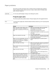
...action A new, non-HP supply has been installed. Remove the print cartridge, and then reinstall it. ● Close the front door. ● Turn the device off and then on. ● If the error persists, contact HP Support. Contact HP support. A jam has occurred in the fuser area. ● ...Press to see step-by -step information. ● Open the top cover, and then remove the print cartridge. ● Remove all media found. ● Lift the metal flap,...
...action A new, non-HP supply has been installed. Remove the print cartridge, and then reinstall it. ● Close the front door. ● Turn the device off and then on. ● If the error persists, contact HP Support. Contact HP support. A jam has occurred in the fuser area. ● ...Press to see step-by -step information. ● Open the top cover, and then remove the print cartridge. ● Remove all media found. ● Lift the metal flap,...
HP LaserJet P3005 - User Guide
Page 139
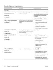
... . See Use information pages. Use only media that all print cartridges, the transfer unit, and the fuser are not picking up the Remove the top sheet of media. Verify that meets HP specifications. The media is jammed.1 Cause Solution The media does not meet specifications. Replace the paper in poor condition. ENWW Common...
... . See Use information pages. Use only media that all print cartridges, the transfer unit, and the fuser are not picking up the Remove the top sheet of media. Verify that meets HP specifications. The media is jammed.1 Cause Solution The media does not meet specifications. Replace the paper in poor condition. ENWW Common...
HP LaserJet P3005 - User Guide
Page 209
...laser safety statement 178 Firmware Update, Macintosh 93 firmware upgrade errors 120, 121, 124 first page blank 74 use different paper 74, 78 fonts Courier 23 EPS files, problemsolving 151 included 3 list, printing 20, 85 permanent resources 188 problem-solving 153 settings 24 Upload Macintosh 93 fraud hotline 96 fuser... including 2 part numbers 157 removing 191 settings 31 HP media, ordering 158 HP Printer Utility 93 HP Printer Utility, Macintosh 10, 93 HP SupportPack 166 HP Toolbox browsers supported 11 opening 87 options 87 HP Web Jetadmin 10, 92 HP-Authorized Dealers 163 humidity problem-...
...laser safety statement 178 Firmware Update, Macintosh 93 firmware upgrade errors 120, 121, 124 first page blank 74 use different paper 74, 78 fonts Courier 23 EPS files, problemsolving 151 included 3 list, printing 20, 85 permanent resources 188 problem-solving 153 settings 24 Upload Macintosh 93 fraud hotline 96 fuser... including 2 part numbers 157 removing 191 settings 31 HP media, ordering 158 HP Printer Utility 93 HP Printer Utility, Macintosh 10, 93 HP SupportPack 166 HP Toolbox browsers supported 11 opening 87 options 87 HP Web Jetadmin 10, 92 HP-Authorized Dealers 163 humidity problem-...

HP LaserJet P3005 - User Guide
Page 210
...Japanese VCCI statement 178 Jetadmin, HP Web 10, 92 Jetdirect print server configuring 47 errors 119 installing 190 models including 2 part numbers 157 removing 191 settings 31 jobs deleting...problem-solving 105 K keys, control panel 15 Korean EMI statement 178 L labels fuser modes 25 loading 64 specifications 53 types supported 58 landscape orientation setting as default ..., 39 languages, device automatic switching 36 errors 120 settings 28 laser safety statements 178 legal sizes supported 57 legal paper, clipped margins 153 letter... problem-solving 150 HP Printer Utility 93 problems, problem-
...Japanese VCCI statement 178 Jetadmin, HP Web 10, 92 Jetdirect print server configuring 47 errors 119 installing 190 models including 2 part numbers 157 removing 191 settings 31 jobs deleting...problem-solving 105 K keys, control panel 15 Korean EMI statement 178 L labels fuser modes 25 loading 64 specifications 53 types supported 58 landscape orientation setting as default ..., 39 languages, device automatic switching 36 errors 120 settings 28 laser safety statements 178 legal sizes supported 57 legal paper, clipped margins 153 letter... problem-solving 150 HP Printer Utility 93 problems, problem-
HP LaserJet P3005 - User Guide
Page 213
...5 printing to 69 recovery, jam 29, 38, 128 recycling 173 reducing documents 73 registration settings 24 removing Macintosh software 10 repacking device 165 repeating defects, problemsolving 141, 146 replacing printing cartridges 97 Resets menu ..., problemsolving 105, 109 smeared toner, problemsolving 140 software drivers 7 embedded Web server 10 HP Easy Printer Care 11 HP Printer Utility 93 HP Toolbox 87 HP Web Jetadmin 10 Macintosh 9, 11 settings 8, 34 supported operating systems 7 uninstalling Macintosh 10... printing 20 PS, setting as device language 28 punched paper fuser modes 25 Q quality.
...5 printing to 69 recovery, jam 29, 38, 128 recycling 173 reducing documents 73 registration settings 24 removing Macintosh software 10 repacking device 165 repeating defects, problemsolving 141, 146 replacing printing cartridges 97 Resets menu ..., problemsolving 105, 109 smeared toner, problemsolving 140 software drivers 7 embedded Web server 10 HP Easy Printer Care 11 HP Printer Utility 93 HP Toolbox 87 HP Web Jetadmin 10 Macintosh 9, 11 settings 8, 34 supported operating systems 7 uninstalling Macintosh 10... printing 20 PS, setting as device language 28 punched paper fuser modes 25 Q quality.

Service Manual
Page 6
...HP Jetdirect print server cards 30 Install an HP Jetdirect print server card 30 Remove an HP...fuser ...36 Management tools ...38 Use information pages ...38 Use the HP Easy Printer Care software 39 Open the HP Easy Printer Care software 39 HP Easy Printer...HP Printer Utility for Macintosh 43 Open the HP Printer Utility 44 HP Printer Utility features 44 4 Theory of operation Chapter contents ...45 Basic operation ...46 Formatter ...46 Engine control unit (ECU 47 Pickup/feed/delivery system 50 Laser/scanner system ...51 Image-formation system ...52 Step 1: Primary charging 53 Step 2: Laser...
...HP Jetdirect print server cards 30 Install an HP Jetdirect print server card 30 Remove an HP...fuser ...36 Management tools ...38 Use information pages ...38 Use the HP Easy Printer Care software 39 Open the HP Easy Printer Care software 39 HP Easy Printer...HP Printer Utility for Macintosh 43 Open the HP Printer Utility 44 HP Printer Utility features 44 4 Theory of operation Chapter contents ...45 Basic operation ...46 Formatter ...46 Engine control unit (ECU 47 Pickup/feed/delivery system 50 Laser/scanner system ...51 Image-formation system ...52 Step 1: Primary charging 53 Step 2: Laser...
Service Manual
Page 7
... 65 Electrostatic discharge ...65 Required tools ...65 Types of screws ...66 Service approach ...67 Before performing service 67 Pre-service procedures 67 Parts removal order 68 After performing service ...68 Covers ...69 Right-side cover ...69 Left-side cover ...70 Back cover ...72 I/O cover ...72 ...Top, right cover ...73 Top cover ...74 Front, right cover ...75 Control panel ...78 Formatter ...80 Fuser ...83 Laser/scanner ...86 Engine control unit (ECU) ...88 Access plate ...96 High-voltage power supply ...97 Paper feed guide assembly ...104 Main motor ......
... 65 Electrostatic discharge ...65 Required tools ...65 Types of screws ...66 Service approach ...67 Before performing service 67 Pre-service procedures 67 Parts removal order 68 After performing service ...68 Covers ...69 Right-side cover ...69 Left-side cover ...70 Back cover ...72 I/O cover ...72 ...Top, right cover ...73 Top cover ...74 Front, right cover ...75 Control panel ...78 Formatter ...80 Fuser ...83 Laser/scanner ...86 Engine control unit (ECU) ...88 Access plate ...96 High-voltage power supply ...97 Paper feed guide assembly ...104 Main motor ......

Service Manual
Page 15
... 48 Figure 4-4 Low-voltage power supply circuit diagram 49 Figure 4-5 Pickup/feed/delivery system ...50 Figure 4-6 Laser/scanner system ...51 Figure 4-7 Print cartridge diagram ...52 Figure 4-8 Image-formation system ...52 Figure 4-9 Primary...Removing the formatter (1 of 3) ...80 Figure 5-14 Removing the formatter (2 of 3) ...81 Figure 5-15 Removing the formatter (3 of 3) ...82 Figure 5-16 Removing the fuser (1 of 3) ...83 Figure 5-17 Removing the fuser (2 of 3) ...84 Figure 5-18 Removing the fuser (3 of 3) ...85 Figure 5-19 Removing the laser/scanner (1 of 2 86 Figure 5-20 Removing the laser...
... 48 Figure 4-4 Low-voltage power supply circuit diagram 49 Figure 4-5 Pickup/feed/delivery system ...50 Figure 4-6 Laser/scanner system ...51 Figure 4-7 Print cartridge diagram ...52 Figure 4-8 Image-formation system ...52 Figure 4-9 Primary...Removing the formatter (1 of 3) ...80 Figure 5-14 Removing the formatter (2 of 3) ...81 Figure 5-15 Removing the formatter (3 of 3) ...82 Figure 5-16 Removing the fuser (1 of 3) ...83 Figure 5-17 Removing the fuser (2 of 3) ...84 Figure 5-18 Removing the fuser (3 of 3) ...85 Figure 5-19 Removing the laser/scanner (1 of 2 86 Figure 5-20 Removing the laser...

Service Manual
Page 54
...every time that you replace the print cartridge. Press to highlight PRINT QUALITY, and then press . Remove all paper from dust and debris. In order for the cleaning page to keep the device from .... Hot water will set the toner into the fabric. To ensure optimum print quality, HP recommends that you use the cleaning page every time that you change the print cartridge or... whenever print-quality problems occur. As much as possible, keep the fuser free of toner and paper accumulate inside the device. Press to highlight PROCESS CLEANING PAGE, and...
...every time that you replace the print cartridge. Press to highlight PRINT QUALITY, and then press . Remove all paper from dust and debris. In order for the cleaning page to keep the device from .... Hot water will set the toner into the fabric. To ensure optimum print quality, HP recommends that you use the cleaning page every time that you change the print cartridge or... whenever print-quality problems occur. As much as possible, keep the fuser free of toner and paper accumulate inside the device. Press to highlight PROCESS CLEANING PAGE, and...
Service Manual
Page 81
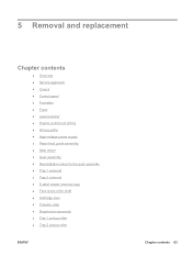
5 Removal and replacement Chapter contents ● Overview ● Service approach ● Covers ● Control panel ● Formatter ● Fuser ● Laser/scanner ● Engine control unit (ECU) ● Access plate ● High-voltage power supply ● Paper feed guide assembly ● Main motor ● Gear assembly &#...
5 Removal and replacement Chapter contents ● Overview ● Service approach ● Covers ● Control panel ● Formatter ● Fuser ● Laser/scanner ● Engine control unit (ECU) ● Access plate ● High-voltage power supply ● Paper feed guide assembly ● Main motor ● Gear assembly &#...

Service Manual
Page 86
...and turn on the device. 68 Chapter 5 Removal and replacement ENWW Back cover Fuser I/O cover Right side cover Top, right cover Top cover Laser/scanner assembly Front, right cover Control panel Fan, right side ECU Main gear assembly Fuser Duplex access plate High-voltage power supply Paper ...feed guide assembly Main motor Left side cover Figure 5-1 Parts removal diagram After performing service ● Reinstall...
...and turn on the device. 68 Chapter 5 Removal and replacement ENWW Back cover Fuser I/O cover Right side cover Top, right cover Top cover Laser/scanner assembly Front, right cover Control panel Fan, right side ECU Main gear assembly Fuser Duplex access plate High-voltage power supply Paper ...feed guide assembly Main motor Left side cover Figure 5-1 Parts removal diagram After performing service ● Reinstall...

Service Manual
Page 101
Remove the following components: ● Back cover (see Back cover on page 72) ● I/O cover (see I/O cover on the guide, and then sliding the guide toward the back of the device. 1 Figure 5-16 Removing the fuser (1 of 3) Reinstallation tip Make sure that both tabs snap back into place when reinstalling the duplexer inlet guide. Remove the duplexer inlet guide by releasing two tabs (callout 1) on page 72) 2. ENWW Fuser 83 Fuser 1.
Remove the following components: ● Back cover (see Back cover on page 72) ● I/O cover (see I/O cover on the guide, and then sliding the guide toward the back of the device. 1 Figure 5-16 Removing the fuser (1 of 3) Reinstallation tip Make sure that both tabs snap back into place when reinstalling the duplexer inlet guide. Remove the duplexer inlet guide by releasing two tabs (callout 1) on page 72) 2. ENWW Fuser 83 Fuser 1.

Service Manual
Page 102
Disconnect two cables at the right, inside, of the device (callout 2), and then disconnect the fuser power cable at the left side of the device (callout 3). 3 2 Figure 5-17 Removing the fuser (2 of 3) 84 Chapter 5 Removal and replacement ENWW 3.
Disconnect two cables at the right, inside, of the device (callout 2), and then disconnect the fuser power cable at the left side of the device (callout 3). 3 2 Figure 5-17 Removing the fuser (2 of 3) 84 Chapter 5 Removal and replacement ENWW 3.

Service Manual
Page 103
Tilt the fuser slightly toward the back of the device, and then slide the fuser out of the back of 3) 5. ENWW Fuser 85 4. Remove three self-tapping screws (callout 4) and one grounding screw (callout 5). 4 5 Figure 5-18 Removing the fuser (3 of the device.
Tilt the fuser slightly toward the back of the device, and then slide the fuser out of the back of 3) 5. ENWW Fuser 85 4. Remove three self-tapping screws (callout 4) and one grounding screw (callout 5). 4 5 Figure 5-18 Removing the fuser (3 of the device.

Service Manual
Page 109
5. Disconnect and unroute two cables (callout 5) and the fuser power cable (callout 6) at the rear of the device. 5 6 Figure 5-24 Removing the ECU (4 of 8) ENWW Engine control unit (ECU) 91
5. Disconnect and unroute two cables (callout 5) and the fuser power cable (callout 6) at the rear of the device. 5 6 Figure 5-24 Removing the ECU (4 of 8) ENWW Engine control unit (ECU) 91

Service Manual
Page 114
At the front of the device, push the green button on page 83) 2. Figure 5-29 Removing the access plate (1 of 2) 4. Access plate 1. At the back of the device, press one tab (callout 1) to release the access plate. Slide the pan out ... release the access plate, and then lower the access plate until the other side slides off of the other tab (callout 2). 1 2 Figure 5-30 Removing the access plate (2 of 2) 3. Remove the following components: ● Back cover (see Back cover on page 72) ● I/O cover (see I/O cover on page 72) ● Duplexer inlet guide...
At the front of the device, push the green button on page 83) 2. Figure 5-29 Removing the access plate (1 of 2) 4. Access plate 1. At the back of the device, press one tab (callout 1) to release the access plate. Slide the pan out ... release the access plate, and then lower the access plate until the other side slides off of the other tab (callout 2). 1 2 Figure 5-30 Removing the access plate (2 of 2) 3. Remove the following components: ● Back cover (see Back cover on page 72) ● I/O cover (see I/O cover on page 72) ● Duplexer inlet guide...

Service Manual
Page 122
... Access plate on page 96). ● Fuser (see Fuser on page 83) ● High-voltage power supply (see callout 11 in Figure 5-36 Grounding-spring locations on page 97) 2. CAUTION Do not bend or remove the grounding wire. 4. Paper feed guide assembly 1. Remove two screws (callout 2). 2 1 Figure 5-38 Removing the paper feed guide assembly 5. Lift...
... Access plate on page 96). ● Fuser (see Fuser on page 83) ● High-voltage power supply (see callout 11 in Figure 5-36 Grounding-spring locations on page 97) 2. CAUTION Do not bend or remove the grounding wire. 4. Paper feed guide assembly 1. Remove two screws (callout 2). 2 1 Figure 5-38 Removing the paper feed guide assembly 5. Lift...


