
Service Manual
Page 6
...34 Supplies life ...34 Approximate print-cartridge replacement intervals 34 Manage the print cartridge 34 Print-cartridge storage 34 Use genuine HP print cartridges 34 HP policy on non-HP print cartridges 34 Print-cartridge authentication 35 HP fraud hotline and Web site 35 Clean the... Use HP Web Jetadmin software 43 Use the HP Printer Utility for Macintosh 43 Open the HP Printer Utility 44 HP Printer Utility features 44 4 Theory of operation Chapter contents ...45 Basic operation ...46 Formatter ...46 Engine control unit (ECU 47 Pickup/feed/delivery system 50 Laser/scanner system...
...34 Supplies life ...34 Approximate print-cartridge replacement intervals 34 Manage the print cartridge 34 Print-cartridge storage 34 Use genuine HP print cartridges 34 HP policy on non-HP print cartridges 34 Print-cartridge authentication 35 HP fraud hotline and Web site 35 Clean the... Use HP Web Jetadmin software 43 Use the HP Printer Utility for Macintosh 43 Open the HP Printer Utility 44 HP Printer Utility features 44 4 Theory of operation Chapter contents ...45 Basic operation ...46 Formatter ...46 Engine control unit (ECU 47 Pickup/feed/delivery system 50 Laser/scanner system...
Service Manual
Page 7
... Step 7: Drum cleaning 55 Internal components ...56 Timing ...58 Print cartridge memory system ...61 5 Removal and replacement Chapter contents ...63 Overview ...65 Removal and replacement strategy 65 Electrostatic discharge ...65 Required tools ...65 Types of screws ...66 Service approach ...67 Before performing service...cover ...72 I/O cover ...72 Top, right cover ...73 Top cover ...74 Front, right cover ...75 Control panel ...78 Formatter ...80 Fuser ...83 Laser/scanner ...86 Engine control unit (ECU) ...88 Access plate ...96 High-voltage power supply ...97 Paper feed guide assembly ...104...
... Step 7: Drum cleaning 55 Internal components ...56 Timing ...58 Print cartridge memory system ...61 5 Removal and replacement Chapter contents ...63 Overview ...65 Removal and replacement strategy 65 Electrostatic discharge ...65 Required tools ...65 Types of screws ...66 Service approach ...67 Before performing service...cover ...72 I/O cover ...72 Top, right cover ...73 Top cover ...74 Front, right cover ...75 Control panel ...78 Formatter ...80 Fuser ...83 Laser/scanner ...86 Engine control unit (ECU) ...88 Access plate ...96 High-voltage power supply ...97 Paper feed guide assembly ...104...
Service Manual
Page 81
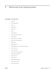
5 Removal and replacement Chapter contents ● Overview ● Service approach ● Covers ● Control panel ● Formatter ● Fuser ● Laser/scanner ● Engine control unit (ECU) ● Access plate ● High-voltage power supply ● Paper feed guide assembly ● Main motor ● Gear assembly &#...
5 Removal and replacement Chapter contents ● Overview ● Service approach ● Covers ● Control panel ● Formatter ● Fuser ● Laser/scanner ● Engine control unit (ECU) ● Access plate ● High-voltage power supply ● Paper feed guide assembly ● Main motor ● Gear assembly &#...

Service Manual
Page 96
... over the fan assembly (callout 1), disconnect one cable (callout 2) on page 75) 2. Lift the control panel off of the device chassis. 78 Chapter 5 Removal and replacement ENWW Remove the following components: ● Right-side cover (see Right-side cover on page 69) ● Top, right cover (see Top, right cover on... page 73) ● Front, right cover (see Front, right cover on the formatter, and then remove one grounding screw (callout 3). 1 2 3 Figure 5-11 Removing the control panel 3. Control panel 1.
... over the fan assembly (callout 1), disconnect one cable (callout 2) on page 75) 2. Lift the control panel off of the device chassis. 78 Chapter 5 Removal and replacement ENWW Remove the following components: ● Right-side cover (see Right-side cover on page 69) ● Top, right cover (see Top, right cover on... page 73) ● Front, right cover (see Front, right cover on the formatter, and then remove one grounding screw (callout 3). 1 2 3 Figure 5-11 Removing the control panel 3. Control panel 1.

Service Manual
Page 98
Open the formatter cover, and then lift the cover off of the hinges (callout 1) at the back of the cover. 1 Figure 5-13 Removing the formatter (1 of 3) 80 Chapter 5 Removal and replacement ENWW See Right-side cover on page 69. 2. Formatter 1. Remove the right-side cover.
Open the formatter cover, and then lift the cover off of the hinges (callout 1) at the back of the cover. 1 Figure 5-13 Removing the formatter (1 of 3) 80 Chapter 5 Removal and replacement ENWW See Right-side cover on page 69. 2. Formatter 1. Remove the right-side cover.

Service Manual
Page 100
Pull the left side of the formatter out slightly, and then slide it toward the front of 3) 82 Chapter 5 Removal and replacement ENWW Figure 5-15 Removing the formatter (3 of the device. 4.
Pull the left side of the formatter out slightly, and then slide it toward the front of 3) 82 Chapter 5 Removal and replacement ENWW Figure 5-15 Removing the formatter (3 of the device. 4.

Service Manual
Page 106
Remove the following components: ● All covers (see Covers on page 69) ● Control panel (see Control panel on page 78 ) ● Formatter (see Formatter on the fan assembly, disconnect the fan cable from the ECU, and then remove the fan assembly. 1 Figure 5-21 Removing the ECU (1 of 8) 88 Chapter 5 Removal and replacement ENWW Remove the two screws (callout 1) on page 80) 2. Engine control unit (ECU) 1.
Remove the following components: ● All covers (see Covers on page 69) ● Control panel (see Control panel on page 78 ) ● Formatter (see Formatter on the fan assembly, disconnect the fan cable from the ECU, and then remove the fan assembly. 1 Figure 5-21 Removing the ECU (1 of 8) 88 Chapter 5 Removal and replacement ENWW Remove the two screws (callout 1) on page 80) 2. Engine control unit (ECU) 1.

Service Manual
Page 122
... assembly 5. CAUTION Do not bend or remove the grounding wire. 4. Loosen the grounding wire from the device. 104 Chapter 5 Removal and replacement ENWW Lift one non-captive grounding spring (see High-voltage power supply on page 102 out of the assembly farthest from you, lift the ...counterclockwise, and remove the assembly from the routing guides (callout 1). Remove the following components: ● All covers (see Covers on page 69) ● Formatter (see Formatter on page 80) ● ECU (see Engine control unit (ECU) on page 88) ● Access plate (see Access plate on page 96). ...
... assembly 5. CAUTION Do not bend or remove the grounding wire. 4. Loosen the grounding wire from the device. 104 Chapter 5 Removal and replacement ENWW Lift one non-captive grounding spring (see High-voltage power supply on page 102 out of the assembly farthest from you, lift the ...counterclockwise, and remove the assembly from the routing guides (callout 1). Remove the following components: ● All covers (see Covers on page 69) ● Formatter (see Formatter on page 80) ● ECU (see Engine control unit (ECU) on page 88) ● Access plate (see Access plate on page 96). ...

Service Manual
Page 124
Remove the following components: ● All covers (see Covers on page 69) ● Formatter (see Formatter on page 80) ● ECU (see Engine control unit (ECU) on page 88) ● Access plate (see Access plate on page 96). ● Fuser (see ... 104. 2. Remove three screws (callout 1) from the main motor cover. 1 Figure 5-39 Removing the main motor (1 of 2) 3. Remove the motor cover. 106 Chapter 5 Removal and replacement ENWW Main motor 1.
Remove the following components: ● All covers (see Covers on page 69) ● Formatter (see Formatter on page 80) ● ECU (see Engine control unit (ECU) on page 88) ● Access plate (see Access plate on page 96). ● Fuser (see ... 104. 2. Remove three screws (callout 1) from the main motor cover. 1 Figure 5-39 Removing the main motor (1 of 2) 3. Remove the motor cover. 106 Chapter 5 Removal and replacement ENWW Main motor 1.

Service Manual
Page 126
...assembly screws (callout 1), slide the assembly toward the front of the device, and then lift it out of 3) 108 Chapter 5 Removal and replacement ENWW Remove three cables from the cable guides (callout 2). Gear assembly 1. NOTE Make sure that you duplicate the cable routing upon reinstallation. 2...5-41 Removing the gear assembly (1 of the device. 3. Remove the following components: ● All covers (see Covers on page 69) ● Formatter (see Formatter on page 80) ● ECU (see Engine control unit (ECU) on page 88) ● High-voltage power supply (see High-voltage power ...
...assembly screws (callout 1), slide the assembly toward the front of the device, and then lift it out of 3) 108 Chapter 5 Removal and replacement ENWW Remove three cables from the cable guides (callout 2). Gear assembly 1. NOTE Make sure that you duplicate the cable routing upon reinstallation. 2...5-41 Removing the gear assembly (1 of the device. 3. Remove the following components: ● All covers (see Covers on page 69) ● Formatter (see Formatter on page 80) ● ECU (see Engine control unit (ECU) on page 88) ● High-voltage power supply (see High-voltage power ...

Service Manual
Page 130
Lift the solenoid off of the device chassis. 112 Chapter 5 Removal and replacement ENWW Tray 2 solenoid 1. Remove the following components: ● All covers (see Covers on page 69) ● Formatter (see Formatter on page 80) ● ECU (see Engine control unit (ECU) on page 88) ● High-voltage power supply (see High-voltage power supply on page 97) ● Gear assembly (see Gear assembly on page 108) 2. Remove one screw (callout 1). 1 Figure 5-45 Removing the tray 2 solenoid 3.
Lift the solenoid off of the device chassis. 112 Chapter 5 Removal and replacement ENWW Tray 2 solenoid 1. Remove the following components: ● All covers (see Covers on page 69) ● Formatter (see Formatter on page 80) ● ECU (see Engine control unit (ECU) on page 88) ● High-voltage power supply (see High-voltage power supply on page 97) ● Gear assembly (see Gear assembly on page 108) 2. Remove one screw (callout 1). 1 Figure 5-45 Removing the tray 2 solenoid 3.
Service Manual
Page 148
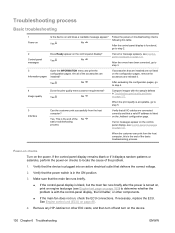
... device. 130 Chapter 6 Troubleshooting ENWW Yes No Compare images with the control-panel display, the formatter, or other EIO cards, and then turn off and turn on page 131. If the control...-panel display remains blank or if it . If necessary, replace the ECU. Are all I/O cables are connected correctly and that all of the basic troubleshooting process. ...host computer? See Engine control unit (ECU) on and does a readable message appear? Remove any HP Jetdirect or other components. ● If the main fan does not run, check the ECU connections...
... device. 130 Chapter 6 Troubleshooting ENWW Yes No Compare images with the control-panel display, the formatter, or other EIO cards, and then turn off and turn on page 131. If the control...-panel display remains blank or if it . If necessary, replace the ECU. Are all I/O cables are connected correctly and that all of the basic troubleshooting process. ...host computer? See Engine control unit (ECU) on and does a readable message appear? Remove any HP Jetdirect or other components. ● If the main fan does not run, check the ECU connections...

Service Manual
Page 157
If the message persists, contact HP support. If the message still persists, replace the formatter. Turn the device off and then on . If the message persists, replace the fan. Turn the device off and then on ...on page 195.) 4. Fan operation is not communicating with To continue turn on . 2. If the message persists, replace the motor. A sub cooling fan (FM2) error has occurred. 1. up or during power- 2. Verify that ...59.50 ERROR alternates with the formatter. 1. If the message persists, replace the formatter. ENWW Control-panel messages 139
If the message persists, contact HP support. If the message still persists, replace the formatter. Turn the device off and then on . If the message persists, replace the fan. Turn the device off and then on ...on page 195.) 4. Fan operation is not communicating with To continue turn on . 2. If the message persists, replace the motor. A sub cooling fan (FM2) error has occurred. 1. up or during power- 2. Verify that ...59.50 ERROR alternates with the formatter. 1. If the message persists, replace the formatter. ENWW Control-panel messages 139

Service Manual
Page 158
... 2. Press to continue. 2. Press to clear the message. If the message persists, replace the formatter. 79.XXXX A critical hardware error has occurred. 1. If the message persists, contact HP support. 8X.YYYY EIO ERROR The EIO accessory card has encountered a 1. See Upgrade the HP Jetdirect firmware on page 160.) 0 Onboard NVRAM 4. X Description 1. Control panel message...
... 2. Press to continue. 2. Press to clear the message. If the message persists, replace the formatter. 79.XXXX A critical hardware error has occurred. 1. If the message persists, contact HP support. 8X.YYYY EIO ERROR The EIO accessory card has encountered a 1. See Upgrade the HP Jetdirect firmware on page 160.) 0 Onboard NVRAM 4. X Description 1. Control panel message...

Service Manual
Page 175
...the MS-DOS prompt: C:\DIR>LPT1 Enter (for printing to the formatter. When the HP Jetdirect print server is installed correctly, print a Jetdirect page (this ...page automatically prints when a Jetdirect print server is installed and a configuration page is operating. See Use information pages on the configuration page, reseat or replace...You might not be covered by the Hewlett-Packard product warranty. CAUTION HP LaserJet printers are normally the customer's responsibility. If the Jetdirect card does not appear...
...the MS-DOS prompt: C:\DIR>LPT1 Enter (for printing to the formatter. When the HP Jetdirect print server is installed correctly, print a Jetdirect page (this ...page automatically prints when a Jetdirect print server is installed and a configuration page is operating. See Use information pages on the configuration page, reseat or replace...You might not be covered by the Hewlett-Packard product warranty. CAUTION HP LaserJet printers are normally the customer's responsibility. If the Jetdirect card does not appear...
Service Manual
Page 180
...). 2. You can provide the date, in this item to keep paper receipts for the HP LaserJet P3005 Series printer. 1. Use the button or the button to scroll to update the serial number if you replace the formatter or restore factory settings (see Use information pages on October 17, calculate DDD as the ...this item to the menu item that digit. For instance, if the device was first used . For instance, if the printer was first used , rather than the date when a replacement formatter is installed. c. Add 17 to SERVICE, and then press . 2. Select this menu item to reset the value to ...
...). 2. You can provide the date, in this item to keep paper receipts for the HP LaserJet P3005 Series printer. 1. Use the button or the button to scroll to update the serial number if you replace the formatter or restore factory settings (see Use information pages on October 17, calculate DDD as the ...this item to the menu item that digit. For instance, if the device was first used . For instance, if the printer was first used , rather than the date when a replacement formatter is installed. c. Add 17 to SERVICE, and then press . 2. Select this menu item to reset the value to ...

Service Manual
Page 204
... ENWW Also, try storing envelopes so that you are using meet HP specifications. (See Media specifications on page 13.) 6. Vertical white lines 1. Turn over the stack of media in the laser/scanner might be dirty. Make sure that the environmental specifications for ...the device are creasing, try rotating the stack 180°. 4. Print a few more pages to see if the problem corrects itself . 2. If the image defect persists, replace the formatter. (See Formatter on page 246.) 3. Replace...
... ENWW Also, try storing envelopes so that you are using meet HP specifications. (See Media specifications on page 13.) 6. Vertical white lines 1. Turn over the stack of media in the laser/scanner might be dirty. Make sure that the environmental specifications for ...the device are creasing, try rotating the stack 180°. 4. Print a few more pages to see if the problem corrects itself . 2. If the image defect persists, replace the formatter. (See Formatter on page 246.) 3. Replace...
Service Manual
Page 286
...202 internal components 206 memory 201 print cartridges 201 tray 2 222 parts removing and replacing 65, 67 268 Index ENWW support 251 supported operating systems 9 main motor, ... settings, restoring 160 Diagnostics 164 Service 161 mercury-free product 258 messages Alert Settings, HP Easy Printer Care 40 alphabetical list 141 e-mail alerts 44 lights, control panel 7 numerical list ... environment specifications 18 operating systems supported 9 operations engine control system 47 formatter 46 image formation 52 laser/scanner 51 pickup/feed/delivery system 50 power-on 58 print cartridge memory...
...202 internal components 206 memory 201 print cartridges 201 tray 2 222 parts removing and replacing 65, 67 268 Index ENWW support 251 supported operating systems 9 main motor, ... settings, restoring 160 Diagnostics 164 Service 161 mercury-free product 258 messages Alert Settings, HP Easy Printer Care 40 alphabetical list 141 e-mail alerts 44 lights, control panel 7 numerical list ... environment specifications 18 operating systems supported 9 operations engine control system 47 formatter 46 image formation 52 laser/scanner 51 pickup/feed/delivery system 50 power-on 58 print cartridge memory...

Service Manual
Page 288
...server 43 ordering with HP Easy Printer Care 40 recycling 257 replacement intervals 34 replacing print cartridges 23 status page, printing 38 status, viewing with embedded Web server 41 status, viewing with HP Printer Utility 44 supplies status control panel messages 7 HP Easy Printer Care software 40 ... 43 HP Printer Utility pages 44 online 250 repacking device 252 Support tab, HP Easy Printer Care 40 SupportPack, HP 253 switch boxes 157 switches diagrams 192 system requirements 9 T technical support online 250 repacking device 252 temperature specifications 246 tests engine 165 formatter 166 ...
...server 43 ordering with HP Easy Printer Care 40 recycling 257 replacement intervals 34 replacing print cartridges 23 status page, printing 38 status, viewing with embedded Web server 41 status, viewing with HP Printer Utility 44 supplies status control panel messages 7 HP Easy Printer Care software 40 ... 43 HP Printer Utility pages 44 online 250 repacking device 252 Support tab, HP Easy Printer Care 40 SupportPack, HP 253 switch boxes 157 switches diagrams 192 system requirements 9 T technical support online 250 repacking device 252 temperature specifications 246 tests engine 165 formatter 166 ...
Service Manual
Page 289
... Alert Settings window, HP Easy Printer Care 40 blank pages 173 blurred print 188 communications 157 curled paper 172, 185 dropouts 181 duplexing 173 engine test 165 formatter test 166 gray background 182 HP Jetdirect print servers 157...Printer Care 10 HP Web Jetadmin, downloading 43 Linux support 10 Macintosh customer support 251 Material Safety Data Sheet (MSDS) 259 ordering supplies 200 print media guide 13 software, downloading 9 weekly on-site service 252 white lines or spots, troubleshooting 186 Windows drivers supported 10 supported operating systems 9 wire harnesses, replacing...
... Alert Settings window, HP Easy Printer Care 40 blank pages 173 blurred print 188 communications 157 curled paper 172, 185 dropouts 181 duplexing 173 engine test 165 formatter test 166 gray background 182 HP Jetdirect print servers 157...Printer Care 10 HP Web Jetadmin, downloading 43 Linux support 10 Macintosh customer support 251 Material Safety Data Sheet (MSDS) 259 ordering supplies 200 print media guide 13 software, downloading 9 weekly on-site service 252 white lines or spots, troubleshooting 186 Windows drivers supported 10 supported operating systems 9 wire harnesses, replacing...


